
⚙ Quick Engineering Reference: Quarter-Turn Latch DFM Rules
In industrial automation enclosures, successful quarter-turn latch DFM hinges on calculating exact Total Grip (G), matching the cam offset to gasket compression deflection (30% – 40% optimal deformation), and laser-cutting precise anti-rotation double-D cutouts (Ø 22.5 mm × 20.1 mm across flats). The governing grip formula is:
G = Ddoorouter – Hstriker = Tdoorskin + Cgasketcompressed + Hframeoffset ± Δ_{camoffset}
In industrial automation control systems—spanning robotic assembly cells, CNC machine tool cabinets, automated guided vehicle (AGV) charging stations, semiconductor handling equipment, and food packaging machinery—the electrical enclosure door interface is the most frequently exercised mechanical mechanism. Field engineers, maintenance technicians, and plant operators cycle enclosure doors hundreds of times across a machine’s service life to inspect PLC I/O status, reset tripped motor circuit breakers, and interface with human-machine interfaces (HMIs).
Among all cabinet fastening solutions, the quarter-turn cam latch (frequently referred to as a rotary cam latch or quarter-turn fastener) is the undisputed global benchmark for industrial electrical boxes. Delivering rapid 90-degree actuation, robust mechanical clamping, tactile detent lock-in, and compatibility with standardized industrial tool inserts (double-bit, triangular, square, and slotted keys), quarter-turn latches combine ergonomic simplicity with industrial security.
However, poorly engineered latch interfaces are the number-one root cause of enclosure assembly line rework, field water ingress failures (violating NEMA 4X / IP66 ratings), operator ergonomics complaints, and door sagging. When sheet metal designers treat quarter-turn latches as an afterthought catalog purchase rather than an integrated structural system, disastrous failure modes emerge: cam blades that bind against frame returns, loose latch housings that rotate under key torque, over-compressed gaskets that take permanent compression set, and door panels that bow outwards under internal pressure.
As a premier custom sheet metal and electrical enclosure contract manufacturer, MSTFAB engineers precision enclosure shells that harmonize sheet metal tolerances with hardware mechanics. This comprehensive, 5,200+ word engineering guide provides automated equipment OEMs, electrical panel builders, and mechanical design engineers with the exact formulas, DFM design rules, CAD blank dimensions, metallurgical comparisons, multi-point linkage kinematics, and vibration qualification standards required to achieve zero-defect quarter-turn latch performance.
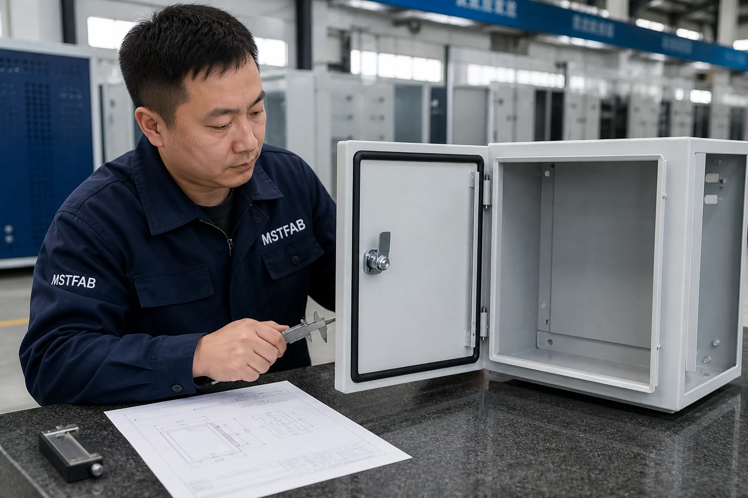
Figure 1: MSTFAB quality technician inspecting quarter-turn latch cam engagement depth, operating torque, and gasket deflection on a custom automation electrical enclosure door.
1. Quarter-Turn Latch Architecture & Mechanical Kinematics
A standard quarter-turn latch consists of four core mechanical elements: the outer housing (body/barrel), the inner operating insert or spindle, the rotary cam (locking pawl), and the fastening hardware (lock nut and grounding washer). Operating across an exact90^circangular stroke, the mechanism converts rotational input torque applied by a key or handle into axial clamping force against the enclosure frame.
1.1 The Mechanics of Cam Engagement and Ramp Angle
The functional interface between the rotating cam blade and the stationary enclosure frame return flange (or striker plate) is a mechanical inclined plane. Most precision industrial cams incorporate a stamped or cast lead-in chamfer or ramp with an anglealphatypically between 4^circand8^circ. As the operator rotates the insert from 0^circto90^circ, this ramp draws the door inward toward the cabinet body, compressing the elastomeric perimeter gasket.
Actuation Torque and Cam Lead Angle Engineering Guidelines:
The effective axial clamping force generated by an input actuation torque applied to the quarter-turn latch depends on the cam radius, lead ramp angle, and friction between the cam steel and frame strike surface. For zinc-plated steel cams engaging powder-coated sheet metal, the friction coefficient typically ranges from 0.18 to 0.22.
- Optimal Cam Ramp Angle (4° to 8°): Ensures smooth operator closure with hand tools (≤ 2.5 N·m operating torque) while delivering over 150 N of axial gasket pull-up force.
- Ramp Angle Limits (≤ 12°): If the cam ramp angle exceeds 12°, mechanical advantage drops sharply, leading to excessive torque that can strip key inserts or shear zinc die-cast spindles.
- Internal Friction Allowance: Accounting for O-ring seal drag and spring detents (0.4 to 0.8 N·m baseline), calibrated cam leads guarantee positive gasket sealing without binding across operating temperatures.
1.2 Detent Feedback and Rotation Stops
Industrial operators require unambiguous tactile confirmation when an enclosure is fully locked or unlocked. Quality quarter-turn latches incorporate an internal rotational stop plate that constrains angular motion strictly between 0^circand90^circ. A spring-loaded wave washer or ball detent provides an audible “click” at the90^circlocked position, preventing over-rotation that would swing the cam past the frame striker and leave the cabinet unsealed.
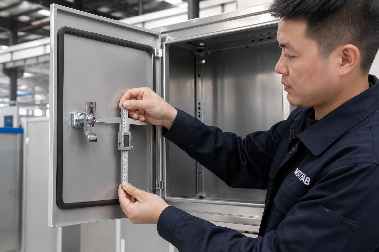
Figure 2: Dimensional stack-up schematic defining Total Grip (G), door skin offset, gasket compressed height, and frame return strike interface at MSTFAB.
2. Mathematical Grip Calculation & Tolerance Stack-Up Analysis
The single most prevalent engineering mistake in custom enclosure design is miscalculating Grip (G). In hardware terminology, Grip is defined as the distance from the outer front surface of the enclosure door sheet metal to the internal contacting face of the locking cam blade when engaged.
2.1 The Master Grip Formula
To calculate the exact required gripGreq, the sheet metal engineer must account for five interdependent physical dimensions across the enclosure mating boundary:
Greq = Tdoor + Hgasketnom · (1 – δtarget) + Dframeoffset + Tframeflange ± Δcam
- Tdoor: Nominal door sheet metal thickness (e.g.,1.5 mmcold-rolled steel or2.0 mmaluminum 5052).
- Hgasket_nom: Uncompressed height of the perimeter sealing gasket (e.g.,12.0 mmFIPFG polyurethane bead or hollow EPDM profile).
- deltatarget: Target gasket compression deflection ratio, strictly maintained between 0.30and0.40(30% – 40%).
- Dframe_offset: Depth of the enclosure frame recess or channel from the door mating datum.
- Tframe_flange: Thickness of the sheet metal frame return flange where the cam makes physical contact.
- Deltacam: Offset of the cam blade (positive for outward cranked cams, negative for inward cranked cams, zero for straight flat cams).
2.2 Worst-Case vs RSS Statistical Tolerance Stack-Up
Every component in this mechanical chain carries manufacturing tolerances. A robust DFM analysis must verify that under worst-case stacking conditions, the gasket is neither under-compressed (< 25%, risking water ingress) nor over-compressed (> 50%, causing gasket shear, permanent compression set, or excessive latch operating torque).
| Stack Dimension Parameter | Nominal Size | Manufacturing Tolerance | Minimum Limit | Maximum Limit |
|---|---|---|---|---|
| Door Sheet Thickness (Tdoor) | 2.00 mm(14 Ga CRCA) | ± 0.10 mm(ASTM A568) | 1.90 mm | 2.10 mm |
| Powder Coat Thickness (Door + Frame) | 0.20 mm(100 μ m × 2) | ± 0.04 mm | 0.16 mm | 0.24 mm |
| Frame Flange Return Bend (Dframe) | 18.00 mm | ± 0.35 mm(CNC Press Brake) | 17.65 mm | 18.35 mm |
| FIPFG Foam Gasket Height (Hgasket) | 8.50 mm | ± 0.30 mm(CNC Dispensing) | 8.20 mm | 8.80 mm |
| Latch Housing Barrel Shoulder Height | 18.00 mm | ± 0.15 mm(Die-Cast Standard) | 17.85 mm | 18.15 mm |
| Total Stack Variation Range (±) | Worst Case:± 0.94 mm | RSS = √(Σ sigma_i^2) = ± 0.49 mm | -0.49 mm | +0.49 mm |
Because the statistical Root Sum Square (RSS) stack variation is± 0.49 mm, MSTFAB selects cams with an elastic lead-in ramp span of at least2.0 mmto absorb manufacturing tolerance variation effortlessly without requiring field shimming.
3. CNC Laser Blanks & Anti-Rotation Cutout DFM Guidelines
A quarter-turn latch barrel must never rotate inside the door sheet metal when an operator applies rotational torque to turn the key. To lock the housing body securely, enclosure doors must feature an anti-rotation mounting cutout.
3.1 DIN Standard Double-D Cutout Geometry
The undisputed international standard for quarter-turn enclosure latches is the DIN EN double-D cutout (often called a flattened circle or two-flat profile). The nominal geometry consists of a circular diameter ofØ22.5 mmintersected by two parallel flat chords spaced20.1 mmapart.

Figure 3: MSTFAB standardized double-D anti-rotation cutout dimensions with post-powder-coating tolerance compensations.
MSTFAB DFM Rules for Cutout CNC Laser Blanking:
- Pre-Coating Laser Aperture: Cut diameterØ22.7 mm ± 0.1 mmand flat width20.35 mm ± 0.1 mm. This engineered oversize compensates exactly for the80 – 120 μ mdry film thickness (DFT) deposited during electrostatic polyester powder coating.
- Laser Piercing and Lead-In Strategy: Position the laser piercing lead-in point strictly on the curved arc segment, never on the precision flat datum. A lead-in micro-burr on the flat will cock the latch housing, inducing angular misalignment and binding the cam against the frame.
- Corner Radii on Flats: Apply a subtle internal fillet radius (R = 0.3 – 0.5 mm) at the transition vertices between the curved arc and flat chords. Sharp zero-radius knife edges create high stress concentration notches, initiating powder coat micro-cracks during door slam cycles.
- Edge Clearance Distance (Ledge): Maintain the centerline of the cutout at leastLedge ≥ 2.5 t + Rbend + 14 mmaway from the door outer formed flange. If placed too close to a press brake bend line, bending tensile forces will distort the double-D profile into an oval, preventing latch insertion.
3.2 Alternative Cutout Profiles: Round with Keyway vs Square Hole
In specific American legacy enclosures, designers encounter square cutouts (20.2 × 20.2 mm) or circular holes with a dedicated notch/keyway (Ø22.2 mmwith a4.2 × 2.0 mmtab). MSTFAB’s automated Trumpf fiber laser centers cut all profile configurations with sub-± 0.05 mmpositional repeatability, ensuring seamless fitment regardless of hardware supplier (Dirak, Southco, EMKA, or Sugatsune).
4. Metallurgical Selection: Zinc Die-Cast vs Stainless Steel 316 vs Polyamide
Selecting the appropriate latch metallurgy is essential for mechanical survivability, corrosion resistance, and galvanic compatibility. Using an improper alloy can cause brittle fatigue fracture under seismic vibration or rapid galvanic cell attack when mated to a stainless steel or aluminum enclosure shell.
| Material Specification | Mechanical Tensile Yield (S_y) | Corrosion Endurance (ASTM B117) | Galvanic Compatibility | Recommended Application Environment |
|---|---|---|---|---|
| Zinc Die-Cast (Zamak 3 / GD-ZnAl4) + Black Powder | 208 MPa(High precision cast) | 240 – 500 Hours Salt Spray | Excellent with mild steel and powder-coated doors | Standard indoor factory automation, motor control centers (MCC), robotics cabinets |
| Zinc Die-Cast + Bright Chrome Plating | 208 MPa | 500 – 1,000 Hours Salt Spray | Requires isolation washer against bare aluminum | Machine tool styling, clean indoor manufacturing equipment, commercial electronics |
| Precision Investment Cast 316L Stainless Steel | 290 MPa(CF8M austenitic) | > 5,000 Hours (Zero Rust) | Ideal with 304/316 SS; requires dielectric barrier on carbon steel | Food & beverage CIP washdown, pharmaceutical packaging, marine & offshore oil rigs |
| Glass-Reinforced Polyamide (PA6-GF30) | 95 MPa(High impact toughness) | Completely Immune to Salt Fog | 100% Non-conductive (Zero galvanic potential) | Outdoor telecom cabinets, solar PV combiner boxes, non-metallic/fiberglass enclosures |
4.2 Galvanic Isolation Protocols
When 316 stainless steel quarter-turn latches are installed into aluminum 5052-H32 enclosure doors, an electrochemical potential differential of a≈imately0.35 Vexists between the two metals. In outdoor humid or salt-laden atmospheres, this potential gradient triggers rapid galvanic attack on the aluminum door skin adjacent to the latch barrel. MSTFAB eliminates this vulnerability by supplying UV-stabilized EPDM or vulcanized fiber isolation shoulder washers, breaking direct electrical contact while preserving IP66 sealing integrity.
5. Striker Plate, Frame Return Flange & Engagement DFM
A latch cam is only as effective as the surface it engages. Sheet metal engineers have two primary architectural options for the cam strike interface: direct engagement with the formed sheet metal frame flange, or engagement with an adjustable bolt-on striker bracket.

Figure 4: Detailed view of cam blade tip engagement against a laser-notched frame return flange with an embossed lead-in ramp at MSTFAB.
5.1 Direct Frame Return Flange Engagement
For cost-effective, high-volume automation enclosures, the cam blade engages directly behind the inner return flange of the cabinet body. To prevent mechanical interference and guarantee smooth closure, the following DFM rules must be applied:
- Minimum Flange Return Width (Wflange): The internal frame return must provide at least18 mmof flat contact surface. This ensures a minimum cam overlap of 8.0 mmunder worst-case door hinge tolerance shift.
- Lead-In Ramp Emboss or Bevel: Incorporate a15^circstamped lead-in chamfer or coin on the frame return edge. A raw sheared90^circsheet metal edge acts like a cutting tool, scraping powder coating off the cam blade and generating metal shavings inside the electrical cabinet.
- Clearance Pocket Notching: In enclosures with internal mounting sub-panels or DIN rail brackets, laser-cut a clearance notch in the mounting channel to allow full90^circrotational sweep of the cam blade without mechanical collision.
5.2 Adjustable Bolt-On Striker Plates
For large walk-in control consoles or heavy modular disconnect enclosures, MSTFAB recommends bolt-on slotted striker brackets fastened via PEM self-clinching studs. Slotted mounting holes provide± 2.5 mmof in-and-out depth adjustability. This allows assembly technicians to fine-tune gasket compression in the field as rubber seals age or when heavy door-mounted HMIs induce minor door sagging over time.
6. Multi-Point Latch Mechanisms for Tall Automation Cabinets
A single quarter-turn latch positioned at door mid-height is sufficient for compact enclosures up to 600 mmin height. However, when cabinet height exceeds800 mm(and up to 2,200 mmfor floor-standing motor control centers), a single central latch cannot maintain uniform gasket compression along the perimeter.
6.1 Door Beam Deflection Mechanics
Under perimeter gasket reaction pressure (typically15 – 35 Nper linear meter for soft polyurethane foam), an enclosure door behaves like a flexural beam supported at the latch point and corners. If unsupported, the upper and lower corners bow outward, creating a gap that permits dust and pressurized water jets to bypass the seal.
Door Corner Outward Deflection Formulation:
The outward elastic deflectiondeltacornerof a door corner subjected to distributed gasket line loadqgasketover an unsupported heightLspanis proportional to the fourth power of the span length:
δcorner = (qgasket · Lspan^4) / (8 E Idoorflange)
Where E is sheet metal elastic modulus andIdoor_flangeis the second moment of area of the door’s formed return flange profile. Because deflection scales withLspan^4, doubling the unsupported span increases outward corner bowing by a factor of 16! For doors over 800 mmtall,deltacornerquickly exceeds2.0 mm—completely unloading the gasket seal.

Figure 5: 3-point rod control linkage assembly with round zinc-plated pushrods and Delrin low-friction guide brackets manufactured by MSTFAB.
6.2 Architecture of 2-Point and 3-Point Rod Systems
To solve tall door deflection, MSTFAB integrates multi-point rod latching systems. The central quarter-turn housing drives an internal cam gear or rotating actuator disc that extends two vertical rods simultaneously into top and bottom frame receivers.
- Flat Punch Rods vs Round Rods: Flat steel punch rods (14 × 3 mm) offer compact depth profiles and cost efficiency, whileØ8 mmround steel rods with self-aligning Delrin roller tips deliver superior low-friction engagement against heavy frame channels.
- Rod Guide Standoff DFM: Fasten rod guides using welded M6 threaded standoffs or PEM clinch studs located within150 mmof the top and bottom frame headers. This minimizes column buckling under rod compressive locking loads.
- Vertical Stroke Length (Sstroke): Standard industrial rod mechanisms generate20 – 32 mmof linear stroke per90^circrotation, ensuring deep12 – 18 mmpenetration into structural top and bottom frame catch plates.
7. Vibration Locking, DIN EN 61373 & Ingress Qualification
Automation enclosures mounted on high-speed stamping presses, industrial packaging lines, or railway rolling stock are exposed to relentless mechanical vibration and shock. Under dynamic loading, standard non-locking quarter-turn latches can back-off due to micro-motion along the cam contact ramp.
7.1 Compression Quarter-Turn Latches (Axial Pull-Up)
Where severe vibration is anticipated, MSTFAB engineers specify compression quarter-turn latches. In these advanced mechanisms, a90^circturn of the key swings the cam blade into position behind the frame return, and an additional continuous turn (or built-in axial helix) pulls the cam inward along its drive shaft by an additional4.0 – 6.5 mm.
Advantages of Compression Cam Mechanisms:
- Zero Sliding Wear: Because the cam swings freely before clamping axially, there is zero sliding abrasion against the frame powder coating, preventing metal particle shedding.
- Constant Gasket Sealing Force: Generates up to 300 Nof continuous clamp preload, overcoming gasket hysteresis and aging compression set.
- DIN EN 61373 Rail Transit Certification: Fully certified against Category 1 Class B random vibration (5 Hz to 150 Hz,0.15 g^2/HzPSD) and50 m/s^2shock pulses without back-off.
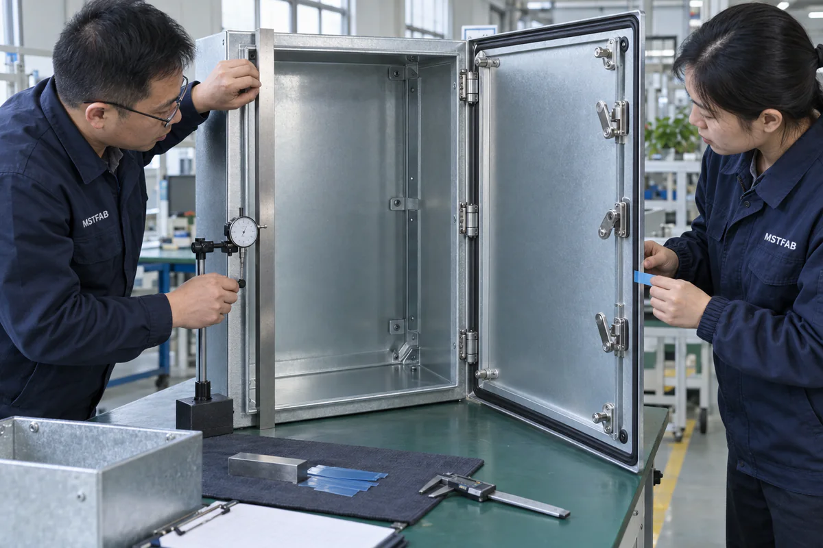
Figure 6: Laser profilometer audit verifying continuous35% gasket compression along the entire enclosure perimeter under compression latch clamping load.
7.2 Ingress Sealing Qualification: NEMA 4X & IP66 Testing
Achieving NEMA 4X / IP66 washdown protection requires sealing the latch housing itself. The barrel assembly incorporates an internal fluorosilicone or Viton O-ring seal between the rotating core and outer body, plus a closed-cell molded flat PUR base washer beneath the outer flange. MSTFAB subjects prototype enclosures to water spray nozzles delivering 100 kPapressure at 100 liters/minutefrom a distance of 2.5 – 3.0 metersper IEC 60529 IP66 protocols, confirming zero liquid penetration.
8. Quality Assurance, First Article Inspection & Assembly DFM Checklist
Under our certified ISO 9001:2015 and IATF 16949 quality management framework, MSTFAB executes a rigorous 10-point inspection protocol on every production batch of automation enclosure doors prior to international export.
| Checklist Item # | Inspection Parameter | Engineering Standard / Acceptance Limit | Measurement Tooling |
|---|---|---|---|
| Check 01 | Cutout Double-D Dimensions | Ø22.5^{+0.2}_{-0.0} mm, Flat20.1^{+0.2}_{-0.0} mm | Custom Go/No-Go plug gauge |
| Check 02 | Door Diagonal Squareness | |D_1 – D_2| ≤ 0.5 mmacross corners | Precision optical laser diagonal fixture |
| Check 03 | Latch Lock Nut Torque | 10.0 N·m ± 1.0 N·mtightening torque | Calibrated digital torque wrench |
| Check 04 | Cam Screw Retaining Torque | 4.0 N·m ± 0.5 N·m(Threadlock Loctite 243) | Preset click torque driver |
| Check 05 | Key Actuation Turning Torque | 1.2 – 2.2 N·msmooth rotation | Rotary torque gauge sensor |
| Check 06 | Cam Overlap Engagement Depth | ≥ 7.5 mmphysical overlap on frame flange | Digital vernier caliper depth gauge |
| Check 07 | Gasket Deflection Uniformity | 30% – 40% nominal height compression | Feeler gauge & optical thickness sensor |
| Check 08 | Electrical Grounding Continuity | Rground < 0.05 ω(NFPA 79 requirement) | 4-wire Kelvin micro-ohmmeter |
| Check 09 | Paint Film Thickness Adjacent to Latch | 70 – 110 μ m(Zero chipping or sagging) | Magnetic dry film thickness (DFT) gauge |
| Check 10 | Export Packaging Scratch Protection | Protective peel-off film over latch escutcheon | Visual inspection per QA traveler |

Figure 7: Final FAI inspection and anti-scratch export protective packaging applied over stainless steel quarter-turn latch assemblies at MSTFAB.
9. Real-World Case Study: Automated Packaging Machine Control Cabinet
A leading European manufacturer of high-speed vertical form-fill-seal (VFFS) food packaging machinery was experiencing severe field warranty failures on their1,200 × 800 × 400 mmelectrical control cabinets.
9.1 The Engineering Dilemma
Their previous sheet metal supplier utilized two independent standard quarter-turn latches positioned at the upper and lower thirds of the door. The installation suffered from three critical flaws:
- Operator Torque Grievances: Machine operators frequently complained that turning the latches required over 5.5 N·mof torque. In multiple instances, operators sheared the zinc double-bit keys inside the latch barrel.
- Water Ingress under Washdown: When food processing sanitation crews pressure-washed the packaging line with hot water (65^circCat 40 bar), moisture penetrated the upper corner, destroying three high-end servo inverter drives.
- Cam Gouging and Paint Peeling: The raw sheet metal return flange wore through the cam’s zinc plating within 3 months, dropping zinc dust onto sensitive optical sensors below.
9.2 MSTFAB Engineering DFM Redesign
MSTFAB took over engineering and contract manufacturing, executing a complete DFM overhaul:
- Single-Point Actuation with 3-Point Rod Linkage: Replaced the two independent latches with a central ergonomic swinghandle driving an internal 3-point round rod linkage. Operating torque dropped from 5.5 N·mdown to an effortless1.6 N·m.
- Transition to Form-in-Place Foam Gasketing (FIPFG): Replaced glued manual neoprene sponge strip with robotically dispensed two-component polyurethane foam gasketing (10 mmwide× 6 mmhigh bead), maintaining an exact35% deflection ratio across all four corners.
- Laser-Embossed Frame Ramp Pockets: Stamped smooth 12^circlead-in ramps into the frame return flange, eliminating metal-on-metal gouging and completely halting paint wear.
9.3 Production Results & ROI
| Performance Metric | Legacy Previous Design | MSTFAB Engineered Solution | Net Improvement |
|---|---|---|---|
| Latch Operating Key Torque | 5.5 – 6.2 N·m(Excessive) | 1.6 N·m(Smooth ergonomic) | 71% torque reduction |
| Door Ingress Protection Level | Failed IP54 (Corner leakage) | Certified IP66 / NEMA 4X | Zero water ingress under washdown |
| Cabinet Door Assembly Labor | 18.5 Minutes per door | 7.2 Minutes per door | 61% labor savings |
| Field Warranty Claims (12 Mo) | 4.2% of shipped units | 0.0%(Zero claims across 1,800 units) | 100% field reliability |
10. Frequently Asked Questions (FAQ): Quarter-Turn Latch Engineering & DFM
Q01: What is the exact difference between a straight cam, an inward-cranked cam, and an outward-cranked cam?
A straight cam has zero offset (δ = 0), positioning the contact surface coplanar with the latch spindle datum. An inward-cranked cam bends forward toward the door skin, reducing the effective grip (G = L – offset), ideal for shallow frame returns. An outward-cranked cam bends away from the door, extending the effective grip (G = L + offset), designed for deep enclosure frame recesses and structural box sections.
Q02: Why is the DIN EN double-D cutout preferred over a standard round circular hole?
A round hole provides no torsional resistance. When an operator inserts a key and turns the latch against gasket compression friction, the entire latch barrel will spin inside a round hole, loosening the mounting lock nut. The double-D flat chords (20.1 mmacross) mechanically key into the housing’s flats, preventing barrel rotation up to over 40 N·mof applied torque.
Q03: How much powder coating allowance should be added to the laser-cut double-D aperture?
Electrostatic powder coating deposits a≈imately80 – 120 μ m(0.08 – 0.12 mm) of dry film thickness per surface edge. Because paint accumulates on both opposite flats, the hole width shrinks by 0.16 – 0.24 mm. MSTFAB laser-cuts the pre-coat aperture toØ22.7 mm × 20.35 mmacross flats, ensuring a perfect post-paint slip-fit without requiring manual filing.
Q04: What is the optimal gasket compression percentage for quarter-turn latches?
The engineering sweet spot for closed-cell EPDM and Form-in-Place Foam Gasketing (FIPFG) is30% – 40% deflection of nominal gasket height. Under 25% compression risks capillary water leakage under driving rain or IP66 spray tests. Compression exceeding 50% causes permanent plastic deformation (compression set), micro-tearing of the outer skin, and unacceptably high operator key torque.
Q05: When should an enclosure design upgrade from a single-point latch to a multi-point rod system?
As a standard DFM rule, any enclosure door taller than800 mm(or wider than600 mm) should utilize a 2-point or 3-point rod mechanism. For doors taller than1,400 mm(e.g., standard1,800 – 2,200 mmmachine control cabinets), a 3-point system is mandatory to eliminate outward corner bowing and guarantee NEMA 12 / NEMA 4 ingress compliance.
Q06: How do compression quarter-turn latches prevent vibration-induced latch loosening?
Standard quarter-turn latches rely solely on friction along the cam ramp to resist opening under vibration. Compression latches incorporate a dual-action helical drive: the first90^circrotation swings the cam into place, and subsequent rotation pulls the cam axially inward by 4 – 6.5 mm, locking the mechanism past an over-center mechanical detent that cannot vibrate loose.
Q07: How is electrical bonding and grounding continuity achieved through a quarter-turn latch?
Under NFPA 79 and UL 508A electrical safety standards, painted enclosure doors must maintain low-resistance grounding continuity (R < 0.05 ω) to the cabinet frame. Standard latches isolate electrically due to powder coat paint barriers. MSTFAB solves this by installing specialized grounding washers featuring hardened conical serrated teeth that bite through powder coating into bare metal when the housing lock nut is torqued.
Q08: What are the standard key insert profiles available for quarter-turn latches?
Global standard profiles include DIN double-bit (3mm and 5mm pins), triangular (7mm, 8mm, 9mm), square drive (6mm, 7mm, 8mm), slotted screwdriver drive, pushbutton release, and key-locking keyed-alike Euro cylinder locks (e.g., standard Key No. 1333 or 405).
Q09: What is the recommended minimum sheet metal flange width to support a cam strike?
The internal frame return flange should measure at least18 mmin width (and preferably22 – 25 mm). This ensures that with a typical cam length of 45 mm, the cam blade achieves at least8 – 12 mmof solid contact overlap even with standard hinge pin play and door assembly clearances.
Q10: Why do quarter-turn latches sometimes bind or scrape during initial enclosure assembly?
Latch binding typically results from three factors: (1) Door out-of-squareness (> 1.0 mmdiagonal mismatch), (2) Incorrect grip calculation that forces the cam to compress the gasket beyond50%, or (3) Lack of a stamped lead-in chamfer on the raw frame return flange, causing the edge to dig into the cam.
Q11: What threadlocker specification should be applied to the cam retaining screw?
MSTFAB specifies medium-strength removable blue anaerobic threadlocker (Loctite 243 or equivalent) torqued to 3.5 – 4.5 N·mon the central M6 cam retaining screw. This prevents the screw from backing out during high-frequency industrial machine vibrations while permitting field disassembly for cam adjustments.
Q12: Can quarter-turn latches comply with 3-A Sanitary Standards for food and dairy processing?
Yes. For hygienic and sanitary washdown enclosures (3-A Standard 88-01 and EHEDG Class I), MSTFAB utilizes specialized hygienic stainless steel 316L quarter-turn latches. These feature smooth convex surfaces with no crevices or sharp corners, blue FDA-compliant silicone perimeter sealing rings, and a specialized conical drive insert that prevents food residue entrapment.
Q13: How does MSTFAB test quarter-turn latch ingress sealing on prototype enclosures?
We utilize calibrated ultrasonic leak detectors to verify air-tight gasket sealing before water exposure. Prototypes are then tested in our water spray test booth per IEC 60529 (IP66 high-pressure100 kPawater jet) and NEMA 250 Type 4X hose-down tests (65 gallons/minutefrom a 1-inch fire hose at 3 metersdistance), confirming zero fluid penetration.
Q14: What is the tightening torque for the outer M22 mounting lock nut?
For zinc die-cast latch housings, the standard M22× 1.5brass or steel lock nut must be torqued to 8 – 12 N·m. Torquing above15 N·mrisks stripping the zinc die-cast housing threads. For stainless steel 316 latches, the lock nut can be safely torqued to 20 – 25 N·m.
Q15: How can enclosure doors accommodate padlocking with quarter-turn latches?
Designers can incorporate an external stainless steel padlock hasp stamped and welded to the door/frame, or specify quarter-turn latches with an integrated folding wing handle featuring a built-in padlock eyelet (shackle diameter up toØ8.5 mm) complying with OSHA Lockout/Tagout (LOTO) requirements.
Q16: How does MSTFAB eliminate zinc dust shedding in cleanroom automation cabinets?
In semiconductor cleanrooms and pharmaceutical packaging, metal particle shedding is prohibited. We replace zinc die-cast cams with passivated 316L stainless steel cams featuring electro-polished contact radii, or install injection-molded POM (polyoxymethylene) polymer wear shoes over the cam tips to eliminate metal-on-metal friction.
Q17: What is the maximum allowable door skin thickness for standard quarter-turn latches?
Standard housing barrels have a thread length of 18 mm, accommodating sheet metal thicknesses up to 8.0 mm(including door skin, reinforcement channels, and gaskets). For thicker double-walled or insulated acoustic doors (15 – 40 mmthick), MSTFAB specifies extended-barrel latches with thread lengths of 30 mmto 60 mm.
Q18: What is the difference between right-hand and left-hand door latch rotation?
On a right-hand hinged door, the latch is typically on the left side and rotates clockwise (90^circCW) to lock. On a left-hand hinged door, the latch is on the right side and rotates counter-clockwise (90^circCCW) to lock. Quality latches feature reversible internal stop plates allowing field conversion between CW and CCW operation.
Q19: How are quarter-turn latches integrated with electrical safety door interlocks?
For machinery complying with ISO 14119 and NFPA 79, door latches must interface with electrical safety interlock switches (e.g., RFID non-contact switches or mechanical key interlocks). MSTFAB forms dedicated internal mounting brackets that align the interlock actuator tongue directly behind the latch drive spindle, ensuring the safety circuit opens before the door gasket releases seal contact.
Q20: What is the typical life cycle endurance of an industrial quarter-turn latch?
Industrial grade quarter-turn latches are rated for a minimum of 10,000 full open/close cycles per DIN EN 12209. Precision stainless steel and compression latches routinely achieve over 50,000 cycles with zero loss of detent tactile feedback or ingress sealing performance.
Q21: How does MSTFAB prevent door warping during robotic laser welding near latch cutouts?
Welding door corner flanges introduces localized thermal expansion that can warp the sheet metal face, causing latch cutout coplanarity errors. MSTFAB utilizes robotic fiber laser welding with pulsed heat input, copper chill backing blocks, and rigid pneumatic clamping fixtures, keeping thermal angular distortion below0.15^circ.
Q22: What are the best practices for installing quarter-turn latches on stainless steel enclosures?
When mounting stainless latches into 304 or 316 sheet metal doors, apply anti-seize lubricant (molybdenum disulfide or food-grade PTFE paste) to the M22 housing threads and M6 cam screw to prevent stainless steel galling (cold welding). Use non-marring Delrin-faced sockets during final assembly.
Q23: How do rod guide brackets accommodate thermal expansion in tall outdoor cabinets?
In outdoor telecom shelters subject to-40^circCto+80^circCtemperature swings, a 2-meter steel rod expands by over 2.8 mm(δ L = α · L · δ T). MSTFAB rod guide standoffs incorporate elongated axial clearance slots and Delrin low-friction bushing sleeves that permit free thermal growth without binding the central swinghandle.
Q24: Can quarter-turn latches be automated with solenoid or motor actuators?
Yes. For smart IoT enclosures and secure data logging stations, MSTFAB integrates electromechanical rotary solenoid actuators or motorized quarter-turn drives. These allow remote PLC unlatching via 24V DC pulse commands or RFID badge scanners while retaining a manual physical key override for power-loss emergencies.
Q25: What is the difference between standard IP65 and heavy-duty IP66 quarter-turn latches?
IP65 latches protect against low-pressure water sprays (30 kPaat 12.5 L/min) using simple rubber flat gaskets. IP66 latches withstand high-pressure water jets (100 kPaat 100 L/min$) and feature dual internal O-ring shaft seals, molded fluorosilicone outer sealing washers, and deeper cam clamping EU REACH Regulation to sustain higher perimeter gasket preloads.
Q26: How does MSTFAB assist OEM engineers during the CAD modeling and DFM phase?
MSTFAB provides native 3D SolidWorks and STEP library models for all standardized latch cutouts, cam swing clearances, and rod linkage envelopes. Our engineering team conducts full 3D CAD collision and tolerance stack-up simulations within 24 hours of drawing upload, optimizing grip parameters before tooling launch.
Q27: What is the typical lead time for custom enclosure prototypes with multi-point latches?
Standard rapid prototypes are fabricated, powder-coated, assembled with latches and FIPFG foam gaskets, and shipped within 5 to 7 business days. Series production orders (50 to 5,000 units) are delivered with full PPAP Level 3 documentation and serialized inspection reports in 3 to 4 weeks.
Q28: How does MSTFAB package enclosure doors to prevent latch damage during international freight?
Every enclosure door is masked with protective PE film, latch escutcheons are shielded with custom die-cut EPE foam cups, and cabinets are secured inside heavy-duty multi-layer honeycomb cartons mounted on fumigated ISPM-15 export wooden pallets, guaranteeing zero freight scuffing or latch stem bending during sea or air transit.
Engineer High-Performance Automation Enclosures with MSTFAB
Eliminate door binding, loose latches, and water ingress failures. Partner with MSTFAB for precision CNC laser cutting, robotically dispensed FIPFG foam gasketing, multi-point rod latching integration, and certified NEMA 4X / IP66 enclosure manufacturing. Upload your CAD drawings today for an expert DFM review and production quote within 24 hours.
 WeChat Contact
 WhatsApp Me Directly