Quick answer: Busbar support DFM for a power distribution enclosure means converting the buyer’s approved electrical layout into repeatable sheet metal interfaces. Before fabrication, freeze the enclosure datum system, insulator mounting patterns, support-plane locations, bracket geometry, buyer-defined mechanical loads, barriers, tool paths, cable keep-outs, hardware, coating boundaries, inspection method, and revision. Inspect the relationships after welding and finishing, because a hole that was perfect on the flat blank can become much more adventurous after heat and powder coating.
MSTFAB manufactures drawing-controlled, unpopulated sheet metal enclosure shells and related mechanical parts. Our scope can include cabinet bodies, frames, doors, mounting plates, formed or welded busbar support brackets, buyer-defined insulator mounting plates, support channels, internal partitions, barriers, grounding-stud features, inserted hardware, surface finishing, dimensional inspection, and export packaging. We do not design or supply the electrical busbar system, select insulators, calculate short-circuit forces, determine creepage or clearance, size conductors, perform temperature-rise verification, wire panels, manufacture finished distribution equipment, or certify the completed assembly.
A power distribution cabinet can be square, clean, beautifully coated, and still stop a panel builder on the first afternoon. The outer shell fits. The door closes. Then the buyer’s busbar support assembly meets four brackets that agree on almost everything except where the holes should be.
This is why busbar support geometry deserves its own DFM review. The busbars and insulators belong to the electrical design. The brackets, mounting patterns, support planes, partitions, fasteners, and welded frame belong to the mechanical manufacturing package. They meet in the same cabinet, so the drawings must make the introduction properly.
This guide is for OEM electrical engineers, panel builders, sourcing managers, supplier-quality engineers, and mechanical designers buying custom power distribution enclosure shells. It explains how to control the fabricated metal interfaces around a buyer-defined busbar arrangement without turning the sheet metal supplier into an electrical design authority it is not.
What Is Busbar Support DFM for a Power Distribution Enclosure?
Busbar support DFM is the manufacturing review of the sheet metal structure that locates, supports, protects, and provides access around the buyer’s electrical assembly. The goal is not to redesign the electrical circuit. The goal is to make the released mechanical architecture manufacturable, measurable, repeatable, and suitable for the buyer’s integration process.
The electrical envelope becomes a mechanical input
The buyer should provide the physical envelopes for busbars, insulators, breakers, cable lugs, conductors, barriers, and service tools where they affect metalwork. MSTFAB uses those envelopes to review bracket interference, hole access, bend feasibility, weld access, panel removal, and coating boundaries. A current rating may explain the project, but a laser cutter still needs dimensions.
The support system is more than a collection of brackets
Several brackets may work together as one functional support system. Their relative height, parallelism, center-to-center spacing, and position to the enclosure datum can matter more than the dimensions of any one loose part. Inspecting each bracket in isolation can produce individually acceptable pieces that form one impressively unacceptable assembly.
DFM does not transfer electrical responsibility
The buyer, panel builder, or responsible assembly manufacturer defines electrical clearances, creepage, insulating materials, busbar dimensions, fault-force criteria, current-carrying performance, temperature-rise limits, and applicable verification. MSTFAB can flag missing mechanical inputs and fabricate the approved metal structure. We cannot infer an electrical design from a cabinet width and a hopeful email.
Responsibility Matrix for Busbar Support Metalwork
Good procurement starts by assigning decisions to the party with the right data and authority. The matrix below separates the drawing-controlled sheet metal package from the electrical assembly.
| Decision or work package | Responsible owner | Controlled output |
|---|---|---|
| Busbar material, size, current rating, joints, conductor arrangement, and temperature-rise strategy | Buyer, electrical designer, or responsible assembly manufacturer | Approved electrical design and component BOM |
| Short-circuit forces, support spacing, insulator selection, and required mechanical load criteria | Buyer and qualified electrical or structural engineering team | Approved loads, locations, safety factors, and acceptance criteria |
| Creepage, clearance, insulation coordination, barrier function, and applicable standard interpretation | Responsible assembly manufacturer and qualified compliance team | Released electrical spacing and barrier requirements |
| Enclosure frame, brackets, support plates, channels, barriers, and mounting patterns | MSTFAB manufactures to buyer-approved drawings | Fabricated unpopulated shell and mechanical parts |
| Weld sequence, bending route, fixtures, inserted hardware process, and finish route | MSTFAB within the released mechanical design | Controlled manufacturing plan |
| Mechanical first article and dimensional evidence | MSTFAB performs agreed checks; buyer defines CTQs and approves | FAI report, fixture result, photos, or fit-check record |
| Busbar installation, wiring, torque, energized testing, routine verification, and final certification | Buyer, panel builder, or responsible assembly manufacturer | Completed and verified electrical assembly |
Release the Mechanical Input Package Before CAD Approval
A useful RFQ contains more than a cabinet model. The support package must identify the configuration being quoted and the physical relationships the metalwork must preserve.
| Input | What the buyer should provide | Why it matters |
|---|---|---|
| Controlled geometry | STEP model, dimensioned drawings, part numbers, revisions, and assembly orientation | Connects every support feature to one approved configuration |
| Functional datums | Primary enclosure datum, support centerlines, mounting plane, and origin for patterns | Prevents long tolerance chains through local flanges |
| Electrical keep-outs | Busbar, insulator, breaker, cable lug, conductor, and service-tool envelopes | Stops brackets and stiffeners from occupying integration space |
| Mechanical criteria | Buyer-approved loads, support positions, deflection limits, and attachment requirements | Lets the fabricator review bracket stiffness without guessing electrical fault engineering |
| Finish boundaries | Coated areas, bare-metal pads, protected threads, masked holes, and appearance requirements | Makes finished-state fit and bonding features repeatable |
| Inspection plan | CTQs, tolerances, measurement method, fit dummies, records, and approval milestone | Aligns production evidence with integration risk |
| Change control | PCN triggers, approval route, revision authority, and work-in-process disposition | Prevents an old support frame from meeting a new busbar layout |
Identify the exact supplied configuration
State whether MSTFAB supplies a welded enclosure frame with permanent supports, a loose support kit, a removable internal frame, barriers packed separately, or another defined configuration. Include the finish and installed mechanical hardware. A drawing that says “support as required” is not a released configuration. It is a future meeting.
Provide envelopes and installation sequence
Show not only where components finish, but how they enter the cabinet. A removable frame may require a diagonal insertion path. A barrier may be installed after the busbars but before cable termination. A socket may need radial clearance around a fastener. CAD can hide a component with one click; technicians have to remove it using physics.
Separate critical requirements from preferences
Mark support-plane position, insulator patterns, barrier interfaces, and mounting relationships as CTQs where they control assembly. Keep cosmetic or generous-clearance features at practical fabrication tolerances. A blanket tight tolerance raises inspection cost and still fails to explain which dimension can actually stop production.
Establish Datums for the Entire Support System
A stable datum strategy is the backbone of repeatable busbar support geometry. It should survive cutting, bending, welding, coating, final assembly, and inspection.
Reference a stable enclosure feature
Suitable primary references can include the main frame, a controlled mounting plane, dedicated internal rails, or buyer-defined centerlines. Avoid locating every support from the nearest edge when those edges are created by different bends and weldments. Nearby is convenient for a tape measure. It is not always correct for the assembly.
Avoid long dimensional chains
A chain from side wall to flange, flange to welded channel, channel to bracket, and bracket to insulator hole accumulates cutting, bending, and welding variation. Dimension critical support patterns directly from functional datums where possible. The fewer translations a critical location needs, the fewer opportunities it has to acquire a new personality.
Use common references for parallel rows
Phase, neutral, ground, or other buyer-defined support rows may need controlled relationships. Reference them from the same datum framework when their relative spacing or height matters. This allows the inspection plan to verify the complete geometry rather than proving that every row is excellent in its own private coordinate system.
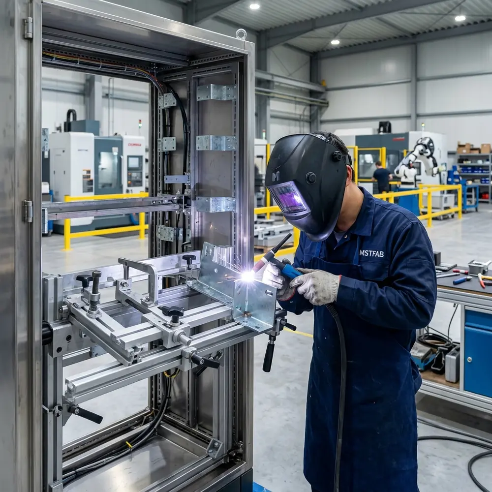
Control Insulator Mounting Patterns as Functional Interfaces
The hole pattern for buyer-selected insulators is one of the most important handoff points between electrical design and sheet metal production. It needs exact product identity, controlled geometry, and finished-state inspection.
Freeze the actual insulator interface
Provide the selected insulator model, mounting footprint, fastener size, seating requirement, access direction, and approved mechanical drawing. Do not design the metalwork from a catalog photograph or a generic description such as “M8 insulator.” A thread size does not define the body diameter, shoulder, seating surface, or tool access.
Inspect the pattern as a pattern
Center-to-center spacing, relative alignment, position to datum, and coplanarity may work together. Check the complete functional pattern using an agreed measurement method or mechanical template. Four holes can each pass an edge dimension and still refuse to meet one rigid assembly. Geometry is capable of teamwork in both directions.
Control support-plane height and flatness
The mounting faces behind several insulators may need to share a controlled plane. The buyer should define the functional requirement and tolerance. MSTFAB can then review formed bracket height, weld distortion, shimming policy if any, and measurement access. Do not hide a plane requirement inside several unrelated dimensions and hope inspection discovers the theme.
Translate Buyer-Defined Loads Into Sheet Metal Criteria
A busbar system can impose mass, assembly, transport, operational, and fault-related loads. The sheet metal supplier needs approved mechanical criteria, not permission to invent the electrical analysis.
The buyer owns load definition
The responsible engineering team specifies support locations, load cases, directions, limits, safety factors, and allowable movement where required. This may come from product design, simulation, testing, or the assembly manufacturer’s verification route. MSTFAB does not derive fault loads from amperes or choose support spacing from a standards headline.
DFM reviews how the bracket carries the approved load
Once criteria are released, manufacturing review can examine flange direction, return bends, section depth, gussets, attachment spacing, material thickness, weld accessibility, and local sheet deformation. The review asks whether the approved bracket can be made consistently and whether the load path reaches a suitable frame feature.
Document assumptions and unresolved criteria
If the project has not released loads or deflection limits, record that gap before production approval. A prototype can be fabricated to provisional geometry only when the buyer knowingly accepts that status. Calling a missing engineering input “supplier standard” does not make the input appear. It merely gives the gap a name badge.
Design Support Brackets for Stiffness and Manufacturability
Bracket stiffness depends on geometry, material, span, and attachment, not thickness alone. A practical design balances the buyer’s mechanical criteria with cutting, bending, welding, hardware installation, and inspection.
Use section geometry before adding material everywhere
Return flanges, channels, beads, formed ribs, or buyer-approved gussets can improve stiffness more efficiently than increasing every surface by another millimeter. The best option depends on load direction, available space, tool access, and production volume. A bend is often economical reinforcement, provided it does not move the problem into the cable zone.
Keep holes and hardware manufacturable near bends
Insulator holes, self-clinching hardware, studs, and clearance slots need enough distance from bend lines for the actual sheet thickness, radius, and tooling. Press access must be considered before deep channels are formed. The final model shows where hardware lives; DFM must also explain how the installation press reaches the address. The sheet metal bending tolerance guide covers the broader forming principles.
Separate locating features from fastening where useful
Clearance holes allow assembly but may not locate a removable support frame repeatably. Buyer-approved tabs, shoulders, slots, stops, or dowel features can establish position while fasteners clamp the assembly. Bolts are talented, but oversized holes should not quietly ask them to perform precision location, fastening, and philosophical guidance at the same time.
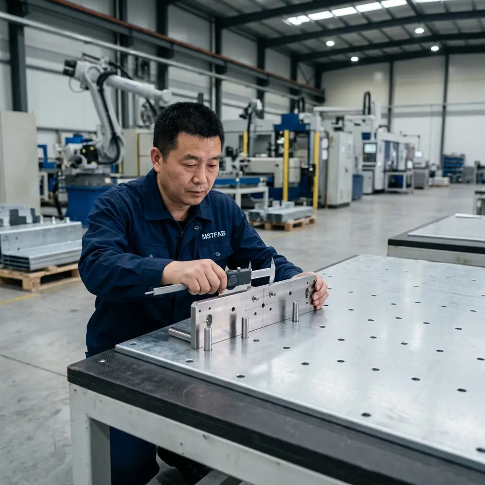
Control Welding Distortion and Support-Plane Flatness
Welding is often the process most capable of moving an otherwise accurate busbar support interface. The manufacturing plan should manage heat, sequence, restraint, access, and post-weld inspection.
Inspect after the process that can move the feature
Laser-cut hole accuracy on a loose bracket does not prove final position after welding. Critical patterns and support planes should be checked in the welded assembly, and again after any finishing step that affects fit. The buyer purchases the finished mechanical relationship, not the excellent blank that existed two processes earlier.
Design fixtures around functional datums
A fixture should control bracket height, spacing, angle, and relative position from the same references used by the assembly. It does not need to restrain every decorative edge. Locators should be accessible, protected from spatter, and periodically verified. “This fixture has always worked” is useful shop history; it is not a calibration record.
Reduce avoidable heat near flat mounting surfaces
Review weld length, location, sequence, symmetry, intermittent weld options where approved, and whether a formed or bolted bracket could protect flatness. The correct route depends on structural criteria and drawing requirements. The goal is not to eliminate welding. It is to prevent the support plate from becoming a gentle landscape when the busbar assembly expected a plane.
Choose Welded or Removable Support Architecture
Permanent and removable structures can both work. The choice should follow assembly sequence, service strategy, load criteria, variant management, tolerance stack, and total cost.
Welded supports reduce hardware but lock the sequence
A welded frame can provide stiffness and reduce loose hardware, but it makes coating, repair, and future revision less flexible. Critical geometry must survive welding, and the buyer must be able to install the electrical assembly around permanent metalwork. A welded bracket has excellent resistance to being misplaced later. It also has excellent resistance to moving when the design changes.
Removable frames can improve bench assembly
A bolted support frame may allow insulators or other buyer-installed items to be assembled outside the cabinet. It can support variants and service access, but introduces locating features, fasteners, tolerance stack, and torque responsibility. Define whether MSTFAB supplies only the metal frame and hardware, while the buyer installs electrical components.
Prove the insertion and removal path
Check the path with doors, returns, barriers, mounting plates, gland structures, and adjacent brackets visible. Include the installed equipment envelope and service condition. A frame that can be removed only before anything important is installed is removable in the same way a building window is removable: technically true, commercially unhelpful.
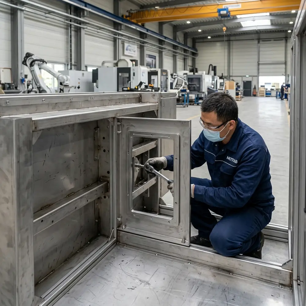
Design Barriers, Partitions, and Tool Access Together
Buyer-defined partitions and barriers can support separation, access control, or assembly organization. MSTFAB fabricates the metal geometry; the responsible electrical team defines the barrier’s required electrical function.
Release barrier function and geometry separately
State which requirements are electrical and which are mechanical. The electrical team defines coverage, spacing, material constraints, access policy, and applicable verification. The drawing then defines fabricated dimensions, mounting points, bends, fasteners, and finish. This prevents the metal supplier from being asked to guess what a barrier must electrically achieve.
Sequence barriers around installation and maintenance
Decide whether each panel is installed before busbars, after busbars, before cable termination, or after final inspection. Check removal direction and staging space. The related electrical enclosure inner-cover DFM guide owns detailed dead-front cutout and service-access design; this article owns the relationship to the support structure.
Reserve real tool and hand clearance
Model sockets, drivers, torque tools, extension bars, and hand access where critical. A screw head can be visible while the tool axis is blocked by a flange. Keep bracket returns and gussets outside approved service envelopes. Tools are three-dimensional objects, despite occasional evidence from crowded CAD assemblies.
Control Hardware, Bends, and Assembly Sequence
Small hardware decisions can change part geometry, process sequence, tooling access, and final support position. Freeze exact mechanical hardware before releasing sheet metal.
Specify exact inserted hardware
Define manufacturer, part number, thread, length, material, finish, installation direction, and approved alternatives for self-clinching nuts, studs, rivet nuts, weld nuts, captive fasteners, and other items. Similar thread descriptions do not guarantee the same hole, sheet-thickness range, installation force, or pull-out performance. The general PEM hardware installation guide covers process considerations beyond this application.
Plan hardware installation before forming
Deep channels and narrow returns can block press tooling. Review whether hardware must be installed before bending, after bending, or in a subassembly. Then check whether the installed hardware interferes with bend tooling. Manufacturing sequence is not background administration; it is part of whether the design can physically exist.
Protect service fasteners from becoming loose-part problems
Where the buyer requires repeat removal, consider captive hardware, retention features, or a documented loose-fastener process. The correct choice follows service and electrical requirements. A single screw at the bottom of a large cabinet has a remarkable ability to turn a five-minute task into a flashlight-based investigation.
Treat Finish, Masking, and Bonding Areas as Geometry
Powder coating protects and identifies the enclosure, but it also adds thickness and electrical insulation. The drawing should control where finish is required, prohibited, or allowed to influence fit.
Allow for coating on close mechanical fits
Tabs, slots, removable panels, locating features, threads, and stacked brackets may fit differently after coating. Review the intended finished condition and define practical clearances. A bare-steel prototype that assembles perfectly is useful evidence, but it is not the final exam when production parts receive powder.
Dimension masking boundaries
Specify circular pads, rectangular zones, protected threads, or other buyer-defined coating-free areas with dimensions and datums. Avoid notes such as “mask grounding point” without a boundary. A masking operator cannot derive the required contact area from the electrical schematic, especially when the schematic is not in the work order.
Keep bonding architecture with the electrical owner
MSTFAB can manufacture grounding studs, holes, and bare-metal interfaces shown on released drawings. The buyer decides protective-earth architecture, conductor sizing, bonding method, continuity requirements, and verification. A hinge, bracket, or mounting plate being metallic does not automatically make it a controlled bonding path.
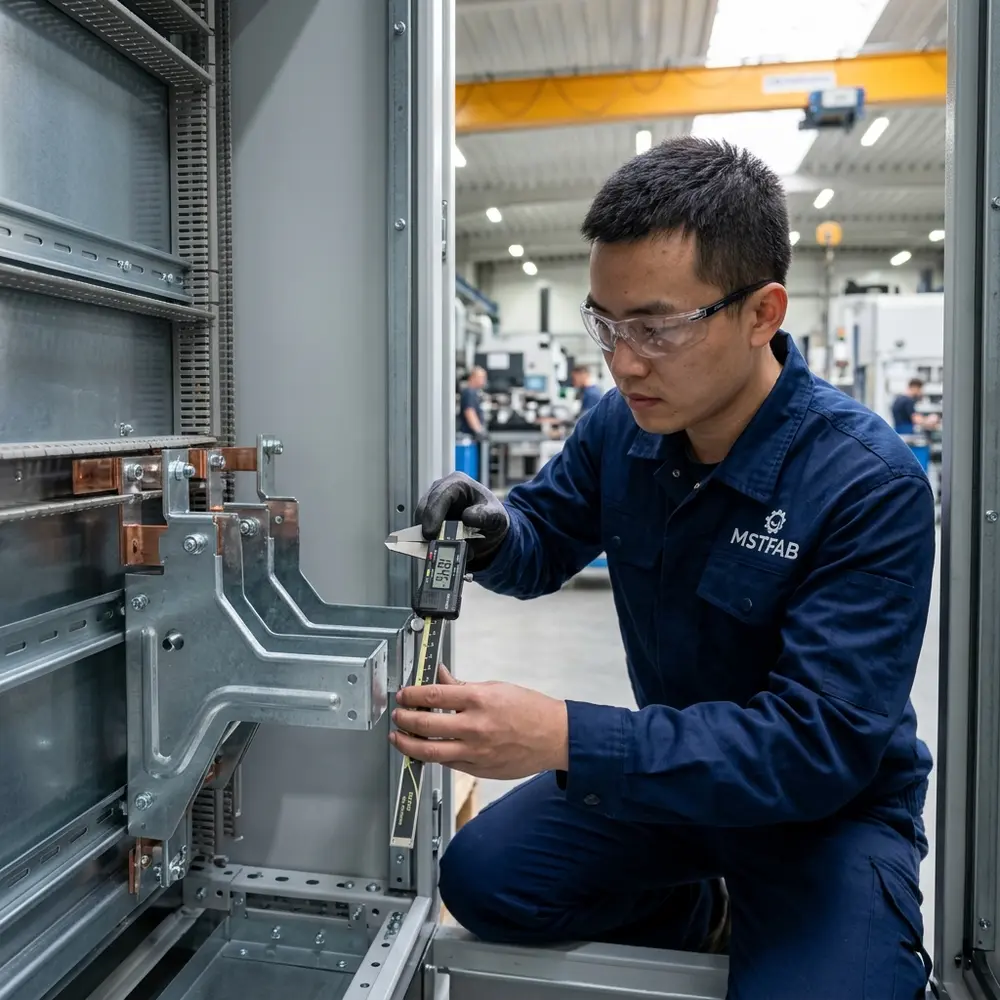
Build a Finished-State Inspection and FAI Plan
Inspection should answer the buyer’s integration questions using the finished assembly condition. The plan needs agreed datums, CTQs, tools, records, and acceptance criteria before the first article is measured.
| Integration risk | Suggested mechanical control | Useful evidence |
|---|---|---|
| Insulator pattern will not match | Check complete hole pattern from functional datums after welding and finish | Dimensional report or buyer-approved checking template result |
| Support faces are not coplanar | Measure support-plane relationship in the assembled frame | Height readings, fixture result, CMM data, or fit dummy |
| Barrier blocks assembly or service | Perform installation and tool-path review with approved envelopes | Assembly photos, marked-up CAD review, or physical trial |
| Hardware cannot be installed or serviced | Verify press access, installed identity, torque-tool approach, and retention | Hardware certificate, installation record, and first-article photos |
| Coating closes a fit or covers a contact zone | Inspect finished clearance, masking dimensions, and protected threads | Finished-state measurements and masking photos |
| Transport bends projecting supports | Inspect packaging restraint and arrival-sensitive geometry | Packing photos and pre-shipment final inspection |
Measure relationships, not only loose parts
Inspect enclosure frame, support brackets, mounting plate, and barriers in the configuration that controls fit. A loose bracket report cannot prove its welded position. The sheet metal FAI and quality-control guide explains broader measurement planning; this article identifies busbar-support CTQs.
Use dummies and templates carefully
A rigid checking plate, dummy insulator pattern, or buyer-supplied gauge can provide strong evidence when it represents the released interface. Identify the gauge revision and acceptance rule. A fixture that fits an old pattern perfectly is still wrong with admirable confidence.
Approve the first article before volume production
Resolve deviations, update drawings, record approved concessions, and freeze the production route before batch release. Prototype handwork must return to CAD and the controlled BOM. “The technician knows to move this bracket 3 mm” is not a scalable manufacturing instruction, even when the technician is excellent.
Keep Standards and Electrical Decisions With the Responsible Team
Standards affect the completed assembly, but a custom empty enclosure shell should not be marketed as though its brackets independently establish complete product compliance.
IEC 61439-2 context does not make the shell an assembly
IEC 61439-2 addresses power switchgear and controlgear assemblies. The responsible assembly manufacturer controls design verification, conductor arrangements, temperature rise, short-circuit withstand, clearances, creepage, protective circuits, and routine verification as applicable. MSTFAB can fabricate released mechanical interfaces that support that program, but does not declare the unpopulated shell to be a verified IEC assembly.
UL context depends on the actual product route
Panelboards, switchboards, and industrial control panels can follow different requirements and certification programs. The official UL industrial control panel program is useful context for applicable control-panel projects, but it is not a universal label for every power distribution cabinet. The UL 508A versus IEC 61439-2 enclosure-shell guide owns the broader standards comparison.
Use scope-accurate supplier language
A defensible statement is: “MSTFAB fabricated the unpopulated sheet metal enclosure shell and support metalwork to the buyer’s released mechanical drawings.” Do not replace that with “MSTFAB certified the busbar system” or “IEC-compliant cabinet” unless a verifiable, applicable certification and responsible entity support the exact claim. Honest scope is less dramatic. It also survives the buyer’s second question.
Control Revisions and Repeat Production
Power distribution platforms evolve. A breaker, busbar arrangement, insulator, cable lug, barrier, or assembly method can change while the exterior cabinet remains identical. The internal metalwork may not share the exterior’s optimism.
Tie every interface to drawing and BOM revision
Control the enclosure assembly, support-frame drawing, loose brackets, hardware BOM, finish specification, checking fixture, and packaging instruction as one released configuration. Identify which support pattern belongs to each electrical variant. Similar-looking internal frames should not rely on memory or marker-pen archaeology.
Define change-notification triggers
Triggers can include insulator model, busbar envelope, support loads, bracket material or thickness, hardware, weld route, fixture locator, coating, masking, barrier, sub-tier supplier, or approved alternative. The buyer decides whether updated DFM, samples, testing, or FAI is required. The supplier change-control guide covers the wider PCN process.
Protect the approved geometry during export
Projecting brackets, studs, barriers, and removable frames need packaging that prevents impact, rubbing, door movement, or stacking load from changing alignment. Loose parts should be identified by part and revision. A support system that passes FAI and arrives bent has completed the manufacturing process but missed the commercial objective.
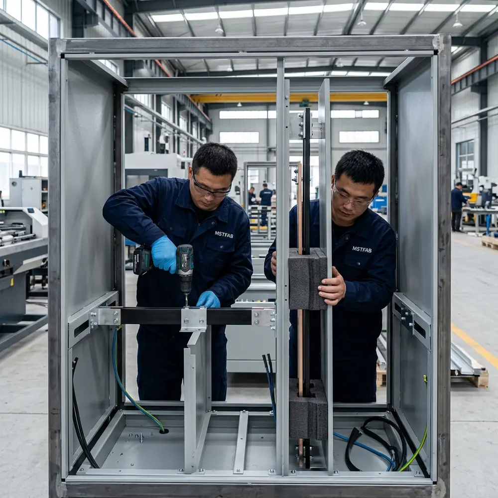
RFQ Checklist for Busbar Support Metalwork
Send a complete mechanical package during quotation so fixture needs, inspection effort, hardware sequence, finish controls, and packaging can be included before the purchase order.
| RFQ item | Buyer input | Supplier output to confirm |
|---|---|---|
| Scope and configuration | Part numbers, revisions, assembly state, quantities, variants, and loose or installed items | Quoted drawing-controlled unpopulated metalwork scope and exclusions |
| Geometry | STEP, PDF drawings, datums, support patterns, planes, and tolerances | DFM comments, manufacturing route, and unresolved questions |
| Electrical envelopes | Approved physical keep-outs for busbars, insulators, breakers, lugs, conductors, and tools | Interference and access review of the metalwork only |
| Mechanical criteria | Approved loads, support positions, deflection or stiffness limits, and attachment rules | Bracket and frame manufacturability review against supplied criteria |
| Materials and hardware | Grades, thicknesses, exact inserted hardware, approved alternatives, and certifications | Controlled BOM and process sequence |
| Finish and masking | Powder specification, color, texture, protected threads, bare pads, and fit allowances | Finish route, masking plan, and finished-state checks |
| Quality evidence | CTQs, gauges, FAI format, records, sample approval, and retention | Inspection plan and evidence package |
| Delivery and change control | Packaging risks, labels, PCN rules, approval lead time, and repeat-order expectations | Packaging method and controlled production-release process |
For broader enclosure sourcing, review the power distribution enclosure buyer guide. For MSTFAB’s drawing-based mechanical scope, see custom electrical enclosure fabrication.
Frequently Asked Questions
Does MSTFAB design the busbar system?
No. The buyer or responsible electrical engineering team defines busbar material, dimensions, arrangement, joints, current rating, insulation, support positions, loads, and verification. MSTFAB manufactures the approved sheet metal support structure and enclosure parts.
Does MSTFAB manufacture finished power distribution equipment?
No. MSTFAB supplies unpopulated enclosure shells and mechanical metal parts made to buyer drawings. We do not supply breakers, wiring, energized assemblies, complete panelboards, or final electrical certification under this fabrication scope.
Can MSTFAB choose busbar support spacing?
Not independently. The responsible engineering team specifies the required support positions and mechanical criteria. MSTFAB can review whether the resulting brackets, plates, holes, bends, and weldments are manufacturable.
Who determines creepage and electrical clearance?
The responsible electrical designer, assembly manufacturer, and qualified compliance team determine applicable creepage and clearance requirements. MSTFAB holds the released mechanical geometry and can inspect physical dimensions identified on the drawing.
What is the most important datum for a busbar support frame?
It depends on the assembly architecture. Common choices include the main enclosure frame, a controlled mounting plane, internal rails, or buyer-defined centerlines. The important point is that all related support rows use a stable, functional reference.
Should insulator holes be inspected individually or as a pattern?
Both may be useful, but the functional pattern is critical when several holes must meet one rigid assembly. Check center-to-center spacing, relative alignment, position to datum, hole size, and support-plane relationship using the agreed method.
Should busbar support brackets be welded or removable?
Either can be correct. Welded supports reduce loose hardware and can improve rigidity; removable frames can improve bench assembly, service, and variant management. Compare load criteria, distortion, tolerance stack, access, finish, and lifecycle needs.
Does powder coating affect busbar support fit?
Yes. Coating can reduce slot clearance, tighten tabs, cover threads, alter stacked fits, and insulate buyer-defined contact areas. Inspect the intended finished condition and dimension required masking boundaries.
How should welded support geometry be inspected?
Inspect critical patterns, heights, planes, and relative positions after welding from the functional datums. Where coating affects fit, repeat the relevant check after finishing. Loose-part measurements alone do not prove welded assembly position.
Can a mechanical template replace a dimensional report?
A buyer-approved template can efficiently confirm a functional pattern, but the quality plan should define what it proves and whether additional dimensional records are required. Control the template revision and verification status.
What should buyers send for a quotation?
Send controlled 3D and 2D drawings, datums, patterns, buyer-approved envelopes, mechanical load criteria, materials, exact hardware, finish and masking requirements, CTQs, inspection format, quantities, variants, packaging risks, and change-control rules.
Conclusion: Make the Metal Support the Approved Electrical Architecture
Reliable busbar support DFM starts with an honest boundary. The buyer controls the electrical design, standards interpretation, busbars, insulators, loads, clearances, testing, and final assembly. MSTFAB controls how the released enclosure shell, brackets, plates, channels, barriers, hardware interfaces, finishes, and packaging are manufactured.
The highest-value work happens before production: establish functional datums, freeze the exact insulator pattern, provide mechanical criteria, protect cable and tool keep-outs, plan welding and hardware sequence, define coating boundaries, and approve finished-state first-article evidence. These controls turn a collection of metal parts into a repeatable mechanical platform for the buyer’s electrical integration.
That is the practical goal. The busbar support frame should be boring at assembly. Excitement is useful in product launches; it is less welcome when four rigid insulators are waiting for the same set of holes.
Written by: MSTFAB Sheet Metal Engineering Team
Technical review: Fabrication and Quality Team
Scope note: General mechanical DFM guidance for buyer-designed enclosure parts, not electrical design or certification advice
Last reviewed: August 2026
 WeChat Contact
 WhatsApp Me Directly