BUILD-TO-PRINT INNER COVER METALWORK
Quick answer: inner cover cutout alignment DFM defines how a buyer-designed secondary panel lines up with equipment behind it after laser cutting, bending, hardware installation and finishing. MSTFAB manufactures the empty enclosure shell, inner cover and drawing-defined mechanical interfaces. MSTFAB does not install electrical devices, perform wiring or certify a finished dead-front assembly.
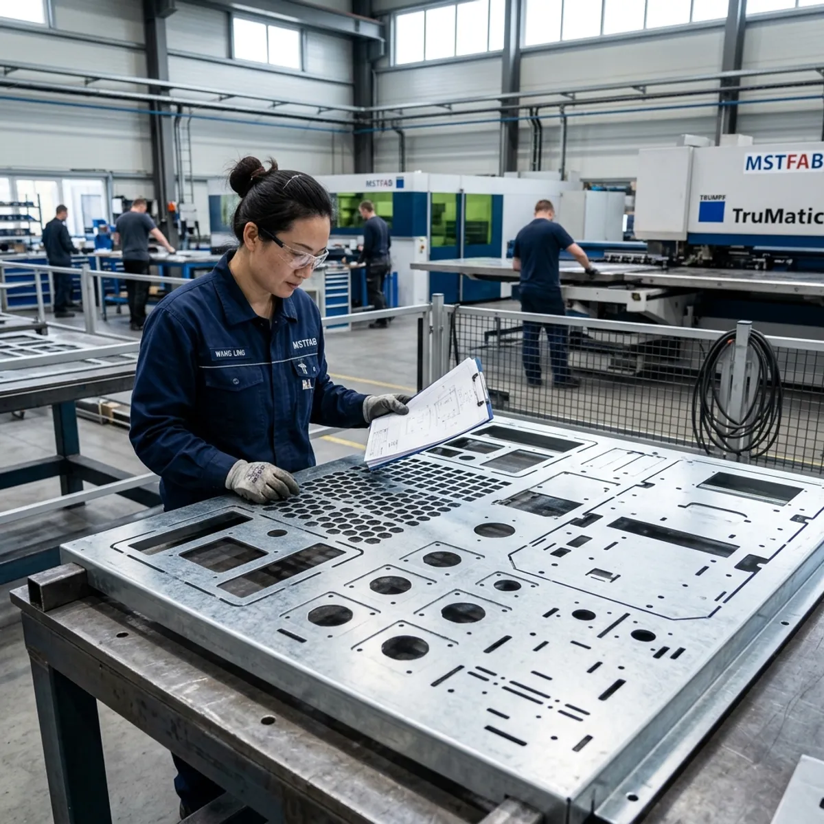
1. Start with the scope, because a panel is not a safety certificate
An inner cover can hide internal components, present selected device faces or create a removable service layer. Buyers may call it an inner panel, swing panel or dead-front-style cover. Those names describe intended use, but the finished electrical function depends on the complete product design.
Empty bodies, doors, inner covers, blank plates, brackets, cutouts, welded studs, specified inserts, hinges, latches, coating, dimensional inspection and export packing.
Breakers, terminals, busbars, wiring, electrical assembly, energized testing, commissioning and certification of the completed equipment.
Electrical architecture, selected devices, access-protection concept, clearances, bonding, component approvals, final testing and product certification.
This division of work is not paperwork theatre. It keeps the metal supplier responsible for measurable metal and keeps electrical decisions with the team that owns the finished product.
2. Freeze the complete interface, not only the visible rectangle
A panel opening is usually the smallest part of the component interface. Behind it sits a body, bezel, mounting clip, terminal block, connector, cable bend or fastener. A cutout can match the catalog face perfectly and still collide with everything that makes the device useful.
The finished window seen from the service side, including corner radii and coating allowance.
The full mechanical envelope behind the panel, including clips, terminals and cable approach.
Hole pattern, insert type, clamp range, screw head and installation tool access.
Space needed to remove the cover or operate the device without dismantling half the cabinet.
A product photograph is useful for a sales meeting. It is a terrible inspection gauge. Provide the component mechanical drawing or STEP model instead.

3. Establish one functional datum system
Locate critical openings from stable assembly references. Depending on the design, those references may be the enclosure opening, the inner-cover mounting face, cabinet centerline, hinge axis or the buyer-defined mounting-plate datum.
Avoid a long chain such as opening A to opening B, then B to C, then C to D. Every tolerance in that chain gets a vote. By the final opening, the votes may have formed a coalition against assembly.
Practical rule: dimensions that must align in the finished enclosure should share functional datums and an agreed measurement condition.
4. Send a quotation package that explains the relationship
For a useful DFM review, send both the assembly context and the controlled part definition. The 3D model explains where the panel lives. The 2D drawing tells production what must be measured.
- Enclosure assembly STEP file
- Controlled inner-cover drawing
- Selected component mechanical models
- Material grade and thickness
- Finished cutout dimensions
- Functional datums and tolerances
- Rear keep-out zones
- Hinge and latch arrangement
- Fastener and insert specifications
- Coating and masking notes
- Inspection method and report needs
- Drawing revision and quantity

5. Control laser-cut features from the released revision
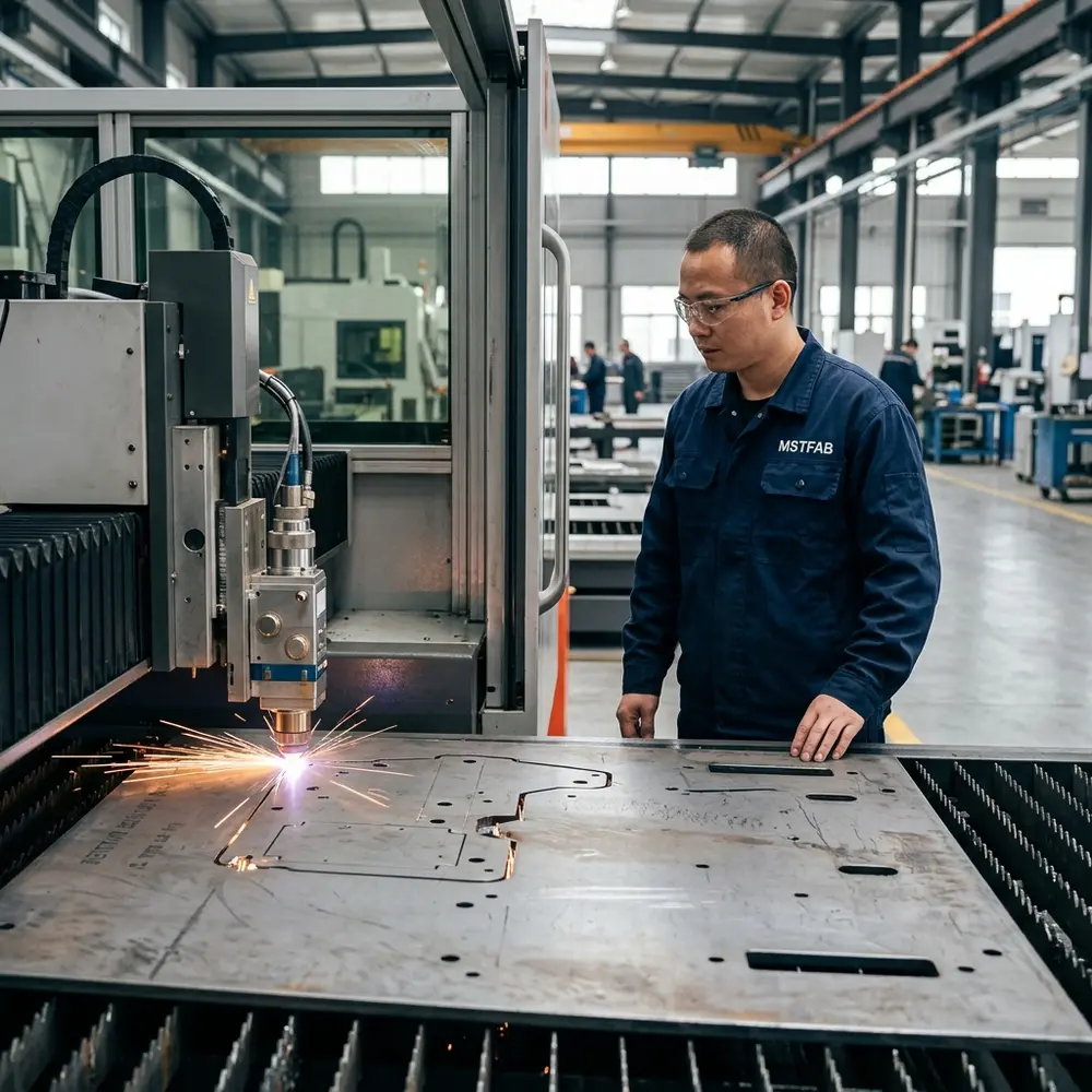
Laser cutting can produce accurate openings, slots and hole patterns, but the production file must match the controlled drawing. Before cutting, MSTFAB checks scale, units, duplicate geometry, open contours, narrow slots, small holes and revision consistency.
Critical openings should include finished size, corner radius and position tolerance. If a hole requires drilling, reaming, tapping or countersinking after laser cutting, that secondary operation belongs on the drawing. The laser is precise; it is not clairvoyant.
6. Review bend geometry before adding more metal
Return flanges can stiffen an inner cover and improve edge appearance. They also consume rear space, affect the flat pattern and create tooling-access limits. Review flange height, inside radius, bend relief, hole-to-bend distance and the sequence needed to form the panel.
When the panel uses several bends, inspect the final functional offset rather than assuming each individual angle tells the whole story. Small angle variations can accumulate across the panel and move an equipment window away from the part behind it.

7. Replace lost stiffness without blocking the component
A large window removes material from the area that was making the panel stiff. The result can be flex, twist or visible waviness around the opening. Options may include return flanges, local channels, formed ribs, spot-welded reinforcement or a justified thickness increase.
Reinforcement needs its own keep-out review. A bar that makes the panel wonderfully rigid while occupying the breaker body is not a structural success. It is an expensive way to manufacture a very confident obstruction.
8. Check tool access and real service movement
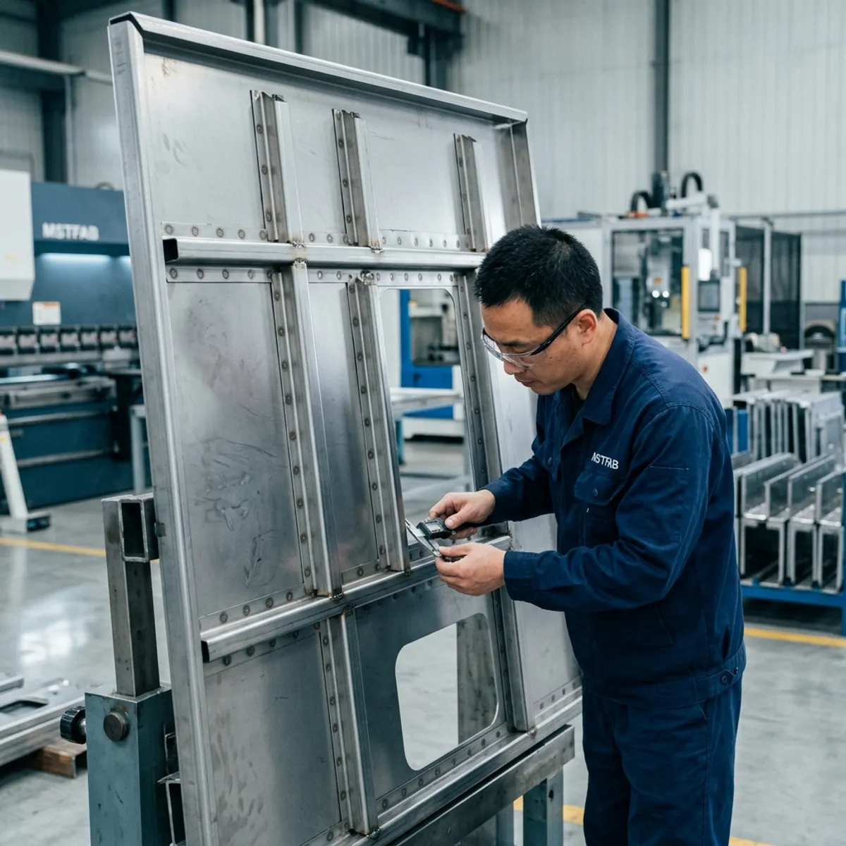
A fastener can be visible and still be impossible to operate. Confirm the screwdriver, socket or quarter-turn tool approach after the buyer’s components are represented in the assembly model. Also check whether the panel can be removed without first removing unrelated brackets.
For a hinged inner cover, define the hinge axis, maximum opening angle, stop position and latch condition. Test the swing envelope against the outer door, gasket flange, sidewall, handles and rear mechanical envelopes.
9. Dimension the finished opening, not a wishful bare-metal opening
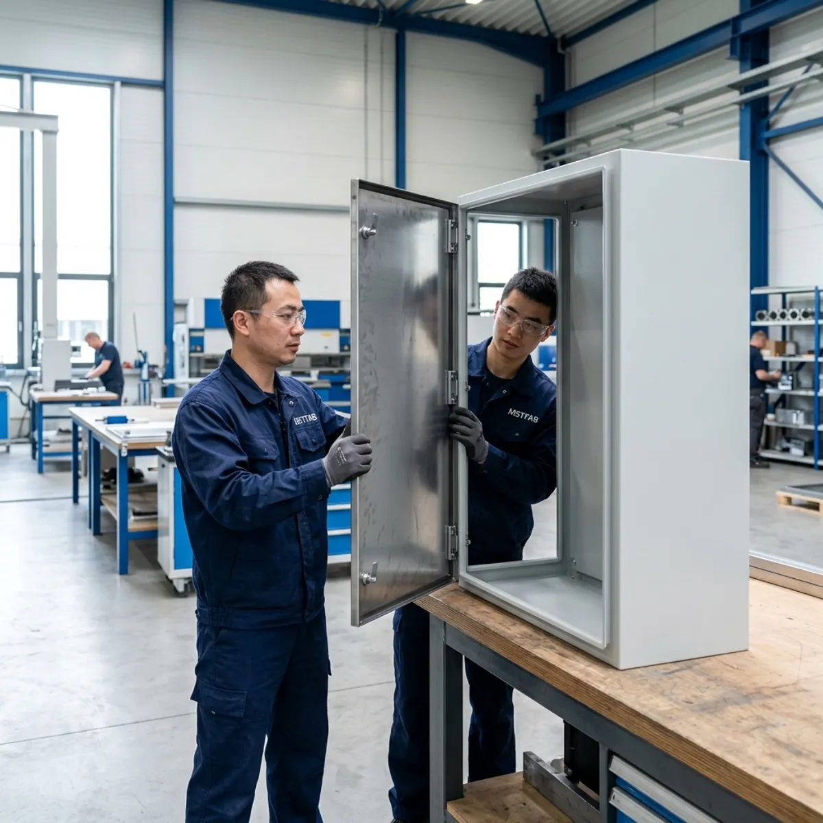
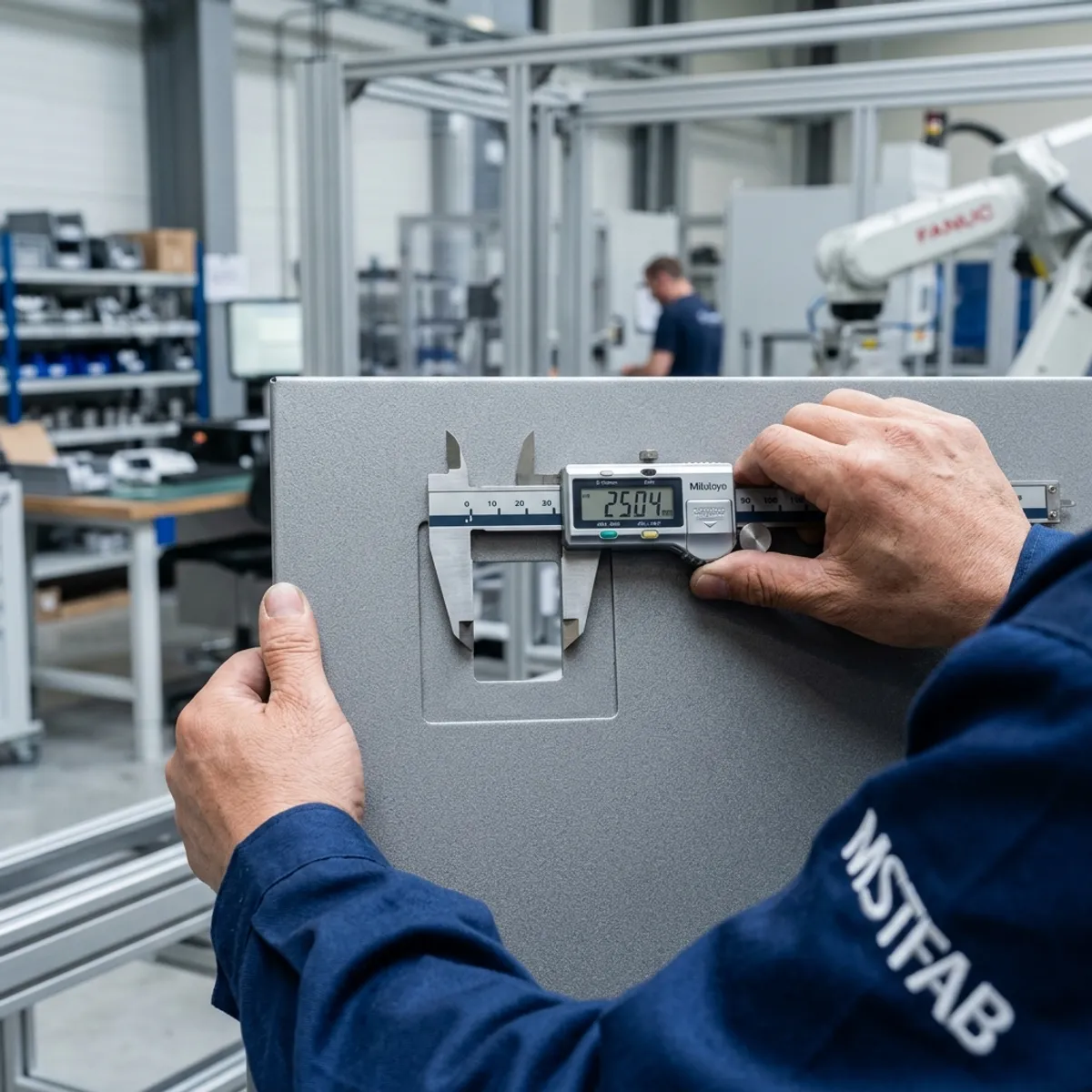
Powder coating changes close-fitting interfaces. It adds material to edges, threaded regions and hinge parts unless masking is specified. Define whether the cutout requirement applies before or after finishing and identify any protected threads, contact pads or precision mounting surfaces.
The bare panel accepts the checking block, but the finished panel does not. The coating did exactly what coating does; the drawing simply forgot to invite it to the tolerance review.
10. Link the inner cover to the mounting plate without merging the drawings
The inner cover and rear mounting plate often share a functional relationship, but they remain separate controlled parts. Define how each part locates to the enclosure, then inspect the assembled relationship.
For the rear interface, use the electrical enclosure mounting plate DFM guide to define stud patterns, plate datums and assembly fit. The inner-cover drawing should reference the approved assembly interface rather than copy uncertain dimensions from another file.
11. Use mechanical dummies and templates for first-article fit
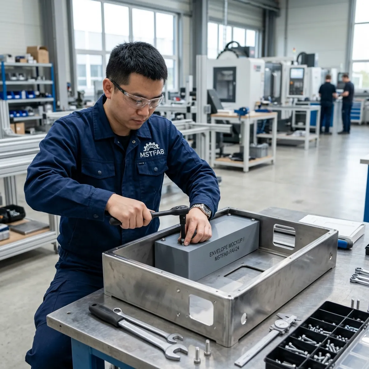
The fabricator does not need powered equipment to perform useful mechanical verification. A buyer can provide a production component sample, 3D-printed dummy, laser-cut checking template or approved gauge that represents the critical envelope.
A dummy block has no firmware, no wiring and no opinions. It only needs to be dimensionally annoying in exactly the same way as the real component. That is enough to catch a great many assembly problems.
12. Agree on the first-article evidence before production
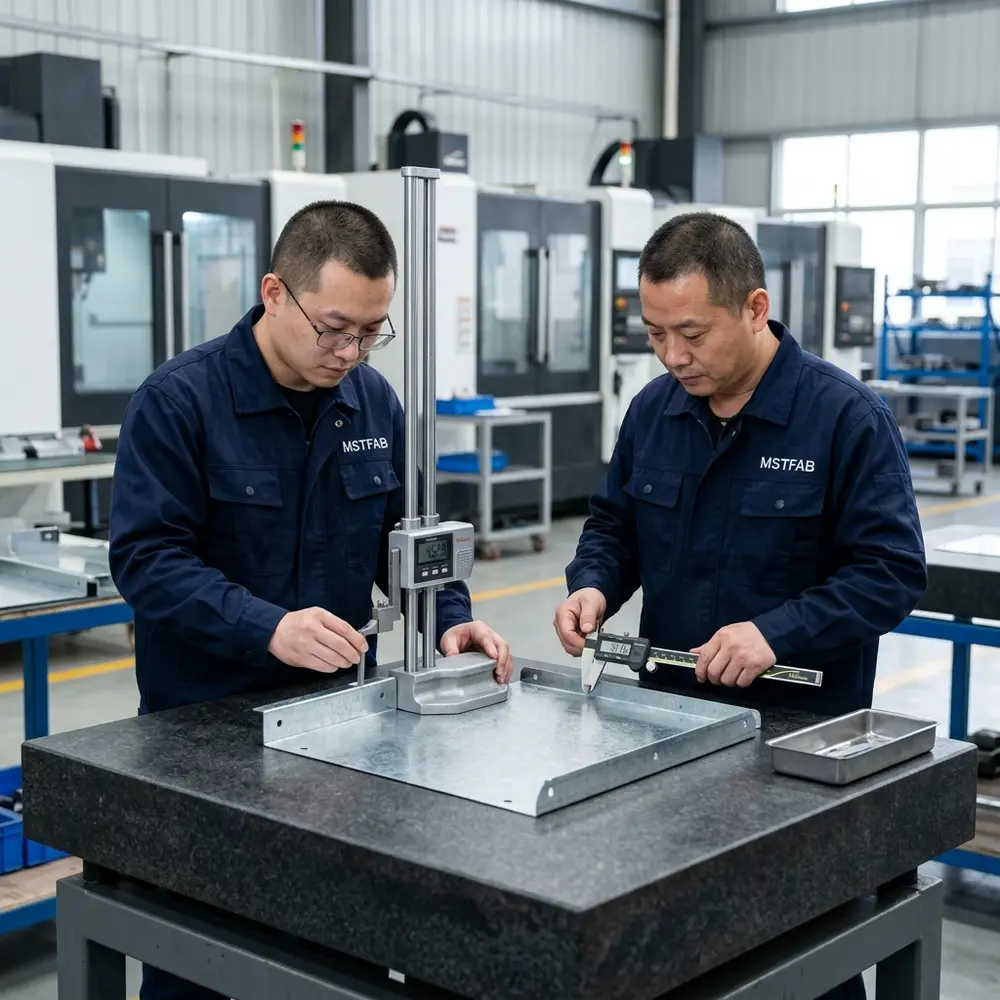
The inspection plan should identify functional datums, finished cutout sizes, opening positions, flange offsets, hinge movement, panel flatness and any buyer-approved fit gauge. A measured number without a defined datum is merely a confident-looking number.
| Feature | Useful control | Evidence |
|---|---|---|
| Cutout location | Common assembly datums | Dimensional report or CMM record |
| Finished opening | Post-coating size requirement | Gauge, caliper or template result |
| Rear clearance | Approved component keep-out | Dummy or sample fit check |
| Panel stiffness | Flatness and reinforcement plan | Surface check and assembly trial |
| Service movement | Defined swing or removal envelope | Photo or video of mechanical trial |
13. Control revisions and similar-looking configurations
Enclosure families often contain several panels that differ by one opening or one hole pattern. Give each panel a unique part number and visible revision. Link inspection records, labels and packing lists to that identity.
Do not call one configuration “the panel with the extra square.” That description works until volume increases or the only person who understands it goes on holiday.
14. Responsibility matrix for an inner-cover project
| Item | MSTFAB mechanical scope | Buyer or integrator scope |
|---|---|---|
| Shell and inner cover | Fabricate to released drawings | Define function and approved geometry |
| Cutouts and fasteners | Manufacture and inspect specified features | Define selected device interface |
| Electrical components | Not supplied or installed | Select, approve, install and wire |
| Access protection | Build buyer-defined metal geometry | Own safety design and validation |
| Certification | Provide agreed mechanical records | Own final product testing and certification |
15. RFQ checklist for fewer assembly surprises
- Controlled STEP and 2D files
- Panel part number and revision
- Material and finished thickness
- Functional datum scheme
- Finished opening tolerances
- Component rear keep-out model
- Fastener and tool access
- Hinge or removal envelope
- Reinforcement restrictions
- Coating and masking requirements
- Fit sample or checking template
- FAI and delivery documentation
Frequently asked questions
Does MSTFAB manufacture a complete dead-front electrical assembly?
No. MSTFAB fabricates buyer-designed empty enclosure shells, inner covers and mechanical parts. The buyer or qualified integrator owns electrical design, installation, testing and certification.
Can MSTFAB design the cutout from a product photo?
A photo can explain appearance, but it cannot define the rear body, clips, terminals or tolerances. Supply a mechanical drawing, STEP model or approved physical sample.
Should the drawing show bare-metal or finished cutout size?
Define the functional finished requirement and clearly state the inspection condition. Close-fitting openings should be reviewed with coating allowance and masking.
Can first-article fit be checked without live electrical equipment?
Yes. A controlled dummy, template, gauge or non-powered sample can verify mechanical alignment and keep-out clearance.
Send the assembly relationship, not only the panel DXF
Share the enclosure assembly, controlled inner-cover drawing, selected component mechanical model, material, finish, quantity and critical inspection points. MSTFAB will review the metal geometry and return practical DFM questions before production.
 WeChat Contact
 WhatsApp Me Directly