BUILD-TO-PRINT MOUNTING PLATE METALWORK
Quick answer: electrical enclosure mounting plate DFM controls how a buyer-designed plate locates inside an empty cabinet shell after cutting, forming, stud welding and finishing. MSTFAB fabricates the shell, mounting plate and drawing-defined mechanical interfaces. We do not select electrical components, wire panels, perform energized tests or certify completed electrical equipment.

1. A mounting plate is simple until two correct parts refuse to assemble
The shell can pass its drawing. The plate can pass its drawing. The two parts can still disagree when the plate meets welded studs, return flanges, the door opening and the buyer’s component pattern. That is why mounting plate DFM must review the assembled interface, not only the flat plate.
Empty enclosure bodies, doors, blank or machined mounting plates, brackets, cutouts, welded studs, specified inserts, finishes, dimensional inspection and export packing.
Breakers, PLCs, terminals, wiring ducts, cables, electrical assembly, energized testing, commissioning and certification of the finished equipment.
Electrical architecture, component selection, load information, bonding design, device approvals, installation procedure, final testing and product certification.
This division matters. It lets a metal fabricator answer measurable questions about metal instead of pretending a caliper can approve an electrical system.
2. Define functional datums before adding dimensions
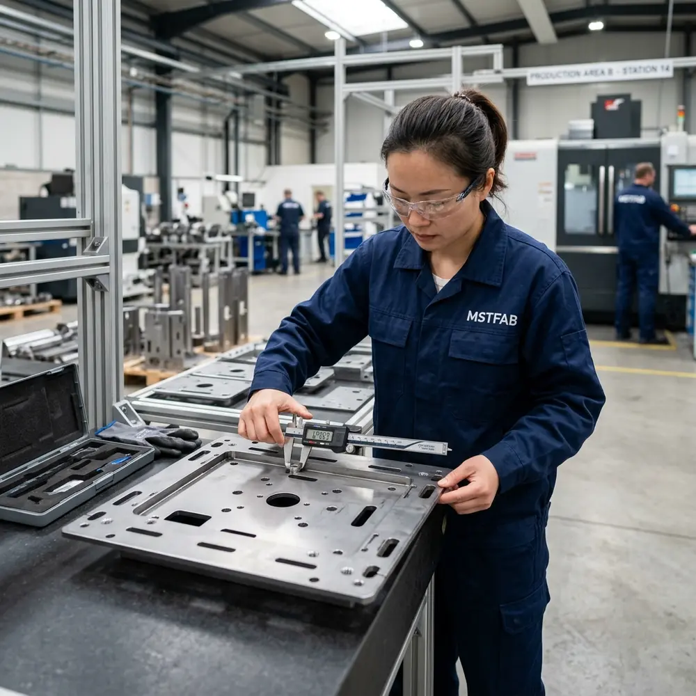
Use stable references that exist in the finished assembly. Common choices include the plate mounting face, enclosure opening, lower support feature, shell centerline or a designated pair of locating studs. Critical holes and component zones should be related to those references.
A long chain from hole A to hole B, B to C and C to D can create cumulative error even when every local dimension is within tolerance. The last hole may be mathematically innocent and mechanically unemployed.
Practical rule: dimensions that must align in the assembled enclosure should share a functional datum system and a stated inspection condition.
3. Send the assembly context, not just a heroic DXF
The flat pattern explains the cut shape. It does not explain how the plate enters the enclosure, what it mounts to or which dimensions matter most. A useful quotation package combines an assembly model with controlled part drawings.
- Enclosure assembly STEP file
- Controlled mounting plate drawing
- Shell and plate part numbers
- Material grade and thickness
- Functional datums
- Critical hole and slot tolerances
- Stud type and finished height
- Component mechanical envelopes
- Plate load and support points
- Finish and masking notes
- Inspection or FAI requirements
- Revision and production quantity

4. Treat hole patterns as functional zones
Not every hole deserves the same tolerance. Separate locating features, fastener holes, adjustment slots, cable-entry features and noncritical accessory holes. Tight control belongs where it protects assembly; global precision mostly protects the quotation from being affordable.
Control the plate’s repeatable position. Use stable datums and avoid unnecessary play.
Provide enough clearance for actual hardware while maintaining the required clamp relationship.
Define adjustment direction, usable travel, edge distance and the fastener head or washer envelope.
Control the complete pattern from functional datums rather than treating each hole as a separate island.
If a mounting pattern comes from a supplier drawing, identify the source revision. A component vendor changing one hole spacing should not become a surprise exercise in creative drilling at final assembly.
5. Specify secondary holes and hardware clearly
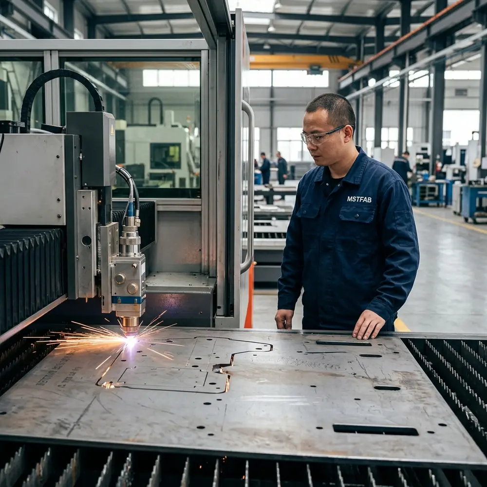
Small holes in thicker plate may need drilling or reaming instead of direct laser cutting. Threads, countersinks, counterbores, PEM hardware, rivet nuts and weld nuts must be shown with type, size, orientation and inspection expectation.
Review installation access before surrounding features are formed or welded. A perfectly specified insert that cannot be reached by the installation tooling is still perfectly useless.
6. Inspect welded studs after welding
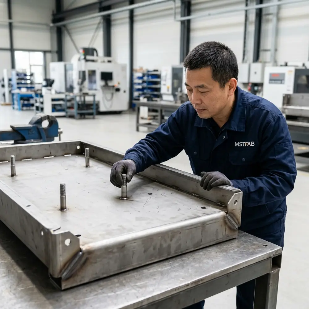
Stud welding introduces heat and real fixture constraints. Define stud type, thread, finished height, location tolerance and any keep-out zone around the weld. The feature should be measured in the condition the buyer receives, not only before the arc starts.
For patterns that support a removable plate, inspect center distance, projection, perpendicularity and fit with the intended plate holes or an approved checking template. The finished mechanical interface is the product of interest.
7. Model the installation path, not just the final position
A large plate may fit beautifully once it is inside the shell but fail to pass through the door opening. Check the path around hinges, latch rods, gasket returns, studs, internal brackets and folded lips. Include any temporary tilt or rotation needed during installation.
Also allow space for hands and tools. CAD assemblies are exceptionally patient: they never drop a washer, scrape a coated edge or ask where the socket extension is supposed to go.
8. Define clearance at the finished condition
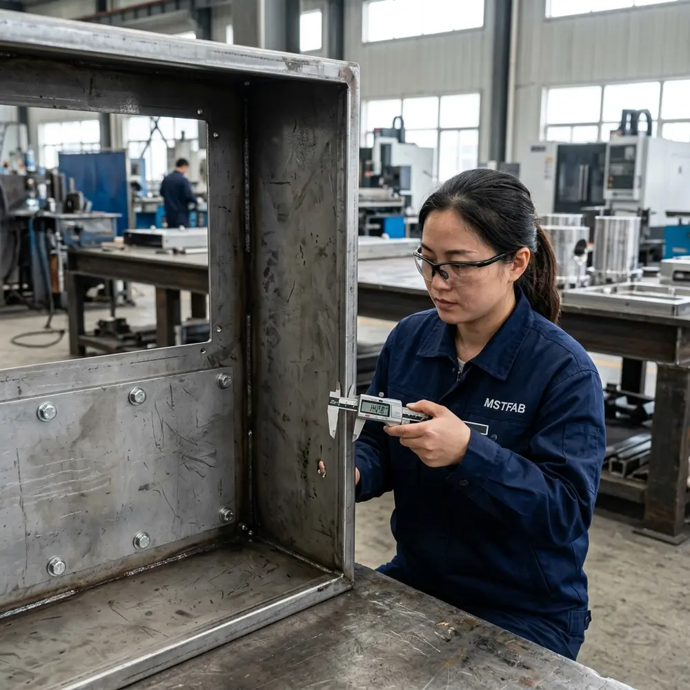
Plate-to-shell gaps should consider formed-part variation, weld distortion, coating thickness and the chosen locating method. A nominal gap that only works when every tolerance lands at the center is not a clearance; it is a wish.
If the plate must sit against spacers, rails or studs, state which surface establishes depth. If shims are allowed, define them. If they are not allowed, do not leave production to discover that rule during assembly.
9. Match plate stiffness to the buyer-defined mechanical load
Thickness is only one part of stiffness. Unsupported span, large cutouts, edge returns, formed ribs, support spacing and component mass all influence deflection. The buyer should identify mass, center of gravity, service loads and any transport or vibration concern relevant to the mechanical design.
MSTFAB can fabricate the released solution and review manufacturability. Final structural acceptance remains with the product owner because the metal shop does not know the complete operating load unless the buyer shares it.
10. Separate locating from fastening
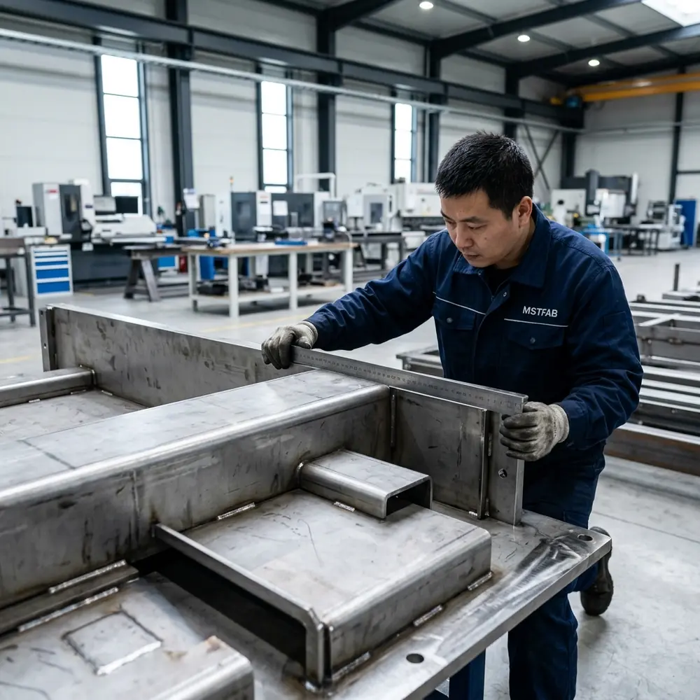
Bolts are good at clamping. They are not always good at repeatable location. Where repeatable plate position matters, use a deliberate locating strategy such as a controlled edge, pilot feature, two locating holes or one round hole plus one slot.
A round-plus-slot arrangement can accommodate expected process variation without allowing the plate to wander freely. The slot direction should follow the intended adjustment direction, not whichever direction looked tidier in CAD.
11. Review coating, masking and bonding interfaces
Powder coating changes close fits and threaded features. Define finished-hole requirements, masked threads, contact pads and any no-coat areas. If the buyer needs an electrical bonding point, the drawing must define its mechanical preparation and protected area; the buyer remains responsible for the final bonding design and electrical validation.
The bare plate fits, the coated plate does not, and everyone stares at the powder as if it arrived without an invitation. Put the finished condition on the drawing before production.
12. Check the plate and inner cover as one interface system
The rear mounting plate and front inner cover may reference the same buyer-installed devices. Their openings, component envelopes and service access must agree even though the two parts have separate drawings. The related inner cover cutout alignment DFM guide explains the front-panel side of that relationship.
A controlled assembly model should remain the shared source of context. Copying dimensions between files by hand is how two drawings become very confident about different realities.
13. Use a functional template when the pattern matters
A buyer-approved checking template can verify several holes, slots and locating features at once. It is especially useful for repeat patterns, retrofit interfaces or multiple plates that must accept the same mechanical assembly.
The template itself needs identification, revision control and a defined use method. Otherwise it becomes a mysterious piece of metal that everyone trusts because it has been in the inspection room for a long time.
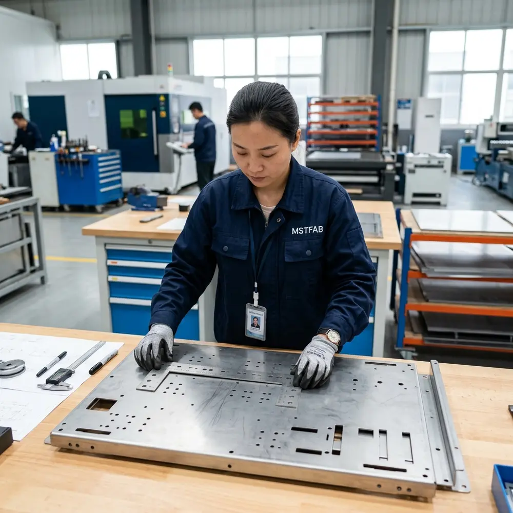
14. Agree on first-article evidence before production
The inspection plan should identify the released revision, material, finish, measurement condition, datums and critical-to-quality features. Use the actual enclosure shell or an approved fixture when the assembled relationship matters.
| Feature | Useful control | Evidence |
|---|---|---|
| Plate location | Functional shell datums | Assembly measurement or fixture result |
| Hole pattern | Basic dimensions and position tolerance | CMM report or approved template |
| Welded studs | Post-weld position and height | Stud inspection record and fit check |
| Installation path | Released shell condition | Mechanical assembly trial |
| Finished interfaces | Post-coating dimensions and masking | Final dimensional and visual inspection |
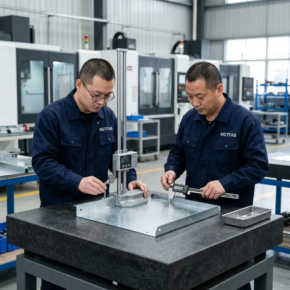
15. Control revisions and similar-looking plates
Cabinet families often contain mounting plates that differ by only a few holes. Give every configuration a unique part number and revision, and connect inspection records, labels and packing lists to that identity.
Do not name them “the left one” and “the other left one.” That naming system performs beautifully until the person who invented it takes a day off.
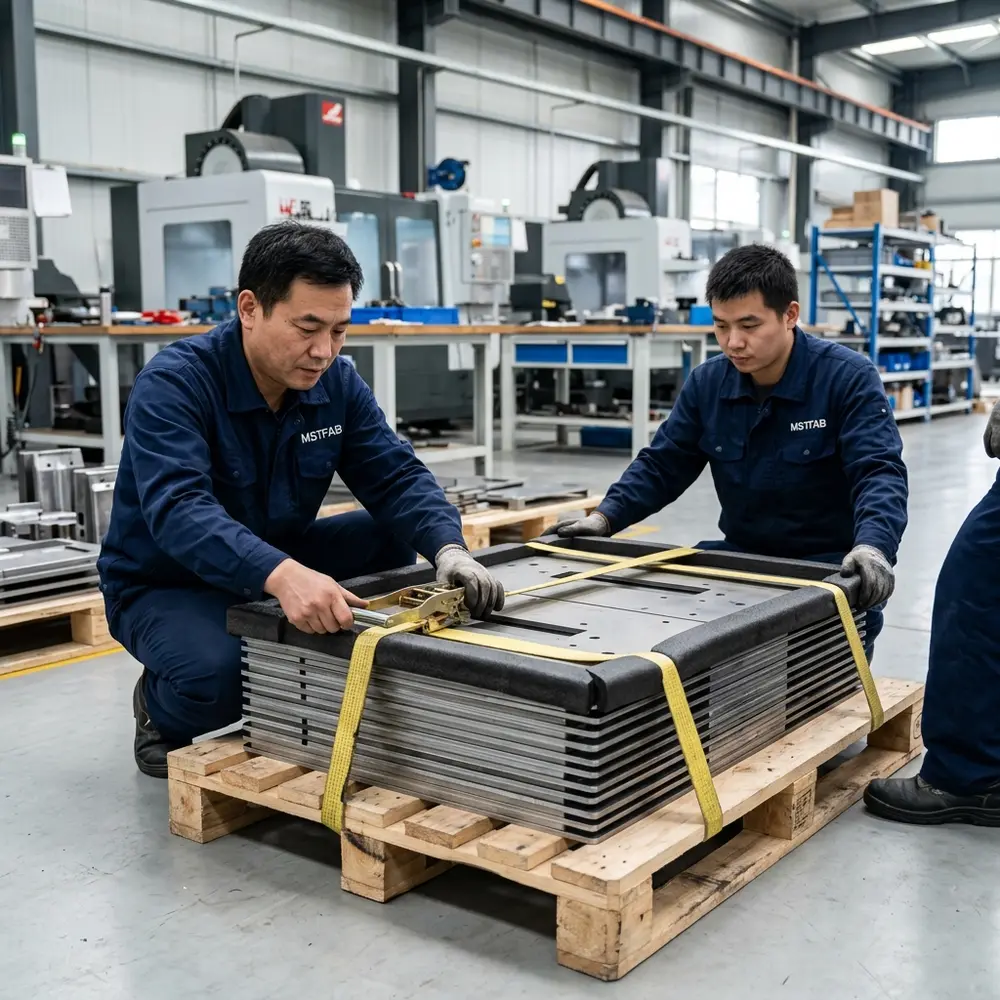
16. Responsibility matrix for a mounting plate project
| Item | MSTFAB mechanical scope | Buyer or integrator scope |
|---|---|---|
| Shell and mounting plate | Fabricate to released drawings | Define function and approved geometry |
| Holes, slots and studs | Manufacture and inspect specified features | Define component pattern and functional tolerances |
| Electrical components | Not selected, supplied or installed | Select, approve, install and wire |
| Mechanical load input | Review fabrication feasibility | Define loads and approve the final design |
| Certification | Provide agreed mechanical records | Own final product testing and certification |
17. RFQ checklist for fewer assembly surprises
- Controlled STEP and 2D files
- Part numbers and revisions
- Material and finished thickness
- Functional datum scheme
- Hole, slot and thread details
- Stud type, position and height
- Installation-path envelope
- Plate load and support points
- Coating and masking requirements
- Fit template or mating sample
- FAI and inspection records
- Packing and delivery destination
Frequently asked questions
Does MSTFAB supply a wired electrical mounting panel?
No. MSTFAB fabricates buyer-designed empty enclosure shells, mounting plates and mechanical parts. The buyer or qualified integrator owns electrical components, wiring, testing and certification.
Can MSTFAB create the component hole pattern from a product photo?
A photo can explain appearance but cannot control hole position, rear envelope or tolerance. Supply the component mechanical drawing, STEP model or an approved physical sample.
Should every mounting hole have a tight tolerance?
No. Tighten locating and function-critical features. Use sensible clearance for ordinary fasteners and define adjustment slots by their intended movement.
Can first-article fit be checked without powered equipment?
Yes. An approved shell, mechanical dummy, template or non-powered sample can verify hole patterns, clearances and installation path.
Send the shell, plate and interface as one RFQ story
Share the enclosure assembly, controlled mounting plate drawing, component mechanical envelope, material, finish, quantity and critical inspection points. MSTFAB will review the build-to-print metalwork and return practical DFM questions before production.
 WeChat Contact
 WhatsApp Me Directly