Release the outdoor EV charging cabinet shell only after the cabinet, site and installer use one controlled interface schedule.
The foundation, anchor pattern, conduit route, finished grade, door swing, cooling-service space, lifting method and field-sealing plan all meet at the enclosure. Concrete is impressively unwilling to move because a CAD datum was vague. Freeze those interfaces before the base is cut and welded.
Give every dimension an owner and a verification point.
An outdoor cabinet can match its shop drawing and still arrive at a site where the anchors, conduits or service clearances do not match. The release package should identify who supplies each input, which revision controls it and how the first article will prove the metal interface.
OEM or integrator
Defines installed equipment, electrical and thermal architecture, cable system, protection targets and completed-product validation.
Site designer
Defines foundation, grade, drainage, conduit routes, site loads, clearances, barriers and installation constraints.
Shell fabricator
Builds the released body, doors, base, cutouts and drawing-defined mechanical interfaces, then records agreed checks.
Installer or test party
Controls handling, anchors, field penetrations, field seals, installed orientation and required as-installed verification.
Use the custom EV charger enclosure service page for the broad commercial fabrication scope. This guide is deliberately narrower: it connects the empty shell to the outdoor site.
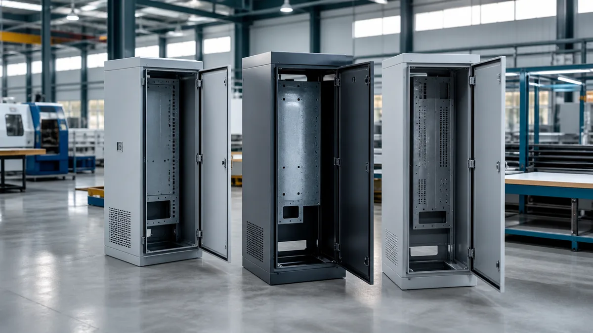
Freeze the base, cable and service datums before fabrication.
| Site interface | Input to release | Useful first-article evidence |
|---|---|---|
| Foundation and anchors | Reference datums, bolt pattern, bolt size, slot policy, base flatness, grout or shim allowance and responsible load data. | Base dimensions, diagonals, hole positions, access for tools and a buyer-approved gauge or template where scoped. |
| Bottom cable corridor | Conduit locations, cable quantities, gland or entry hardware, bend radii, segregation, pull direction and keep-out zones. | Opening and gland-plate dimensions, edge distance, removable-part fit and cable-access clearance. |
| Finished grade and drainage | Installed height, plinth exposure, local slope, standing-water assumptions, drain route and corrosion zones. | Base and drain geometry, open flow path, coating coverage and installation-orientation marking. |
| Doors and service space | Opening direction, door stay, minimum aisle, tool access, removable module path and nearby walls or barriers. | Door swing, stay engagement, latch access and agreed service-envelope trial check. |
| Lifting and placement | Shipping mass, center of gravity, lifting points, forklift pockets, temporary restraints and site handling method. | Lift-point location, fork access, removable lifting hardware and shipping-state photographs. |
| Public and vehicle interface | Bollards, curbs, canopy, impact strategy, user approach, cable reach and accessibility requirements defined by the responsible site team. | Cabinet envelope and mounting-interface records; site compliance remains outside the empty shell scope. |
Every outdoor opening needs a part number, owner and sealing method.
Define each charging-cable exit, conduit entry, display, payment terminal, emergency stop, antenna, fan, heat exchanger and service cover against the selected component revision. A generic rectangle is not an interface schedule.

Component identity
Record supplier, model, revision, cutout, hole pattern, fasteners, gasket or seal and permitted substitution policy.
Cable route
Show cable diameter, bend radius, pull direction, clamp points, edge protection, segregation and connector installation sequence.
Structural effect
Large openings, heavy door-mounted devices and cable loads may require returns, reinforcement or revised hinge and latch positions.
Thermal interface
The OEM owns heat data, cooling selection and completed-system validation; the shell drawing controls the approved mechanical cutouts and supports.
Service removal
Confirm whether a filter, fan, display, gland plate or cooling unit can be removed after the cabinet is anchored and cabled.
Field changes
A field drill is a quick way to turn a controlled enclosure boundary into an experiment. Review new penetrations before work begins.
For high-power equipment internals, continue with the DC fast charger access, cooling and FAI checklist.
The shop seal path and the field installation must agree.
Doors, returns, gasket lands, hinges and latches are only part of the completed boundary. Cable glands, vents, cooling devices, field penetrations and installation orientation can change the result after the shell leaves the factory.
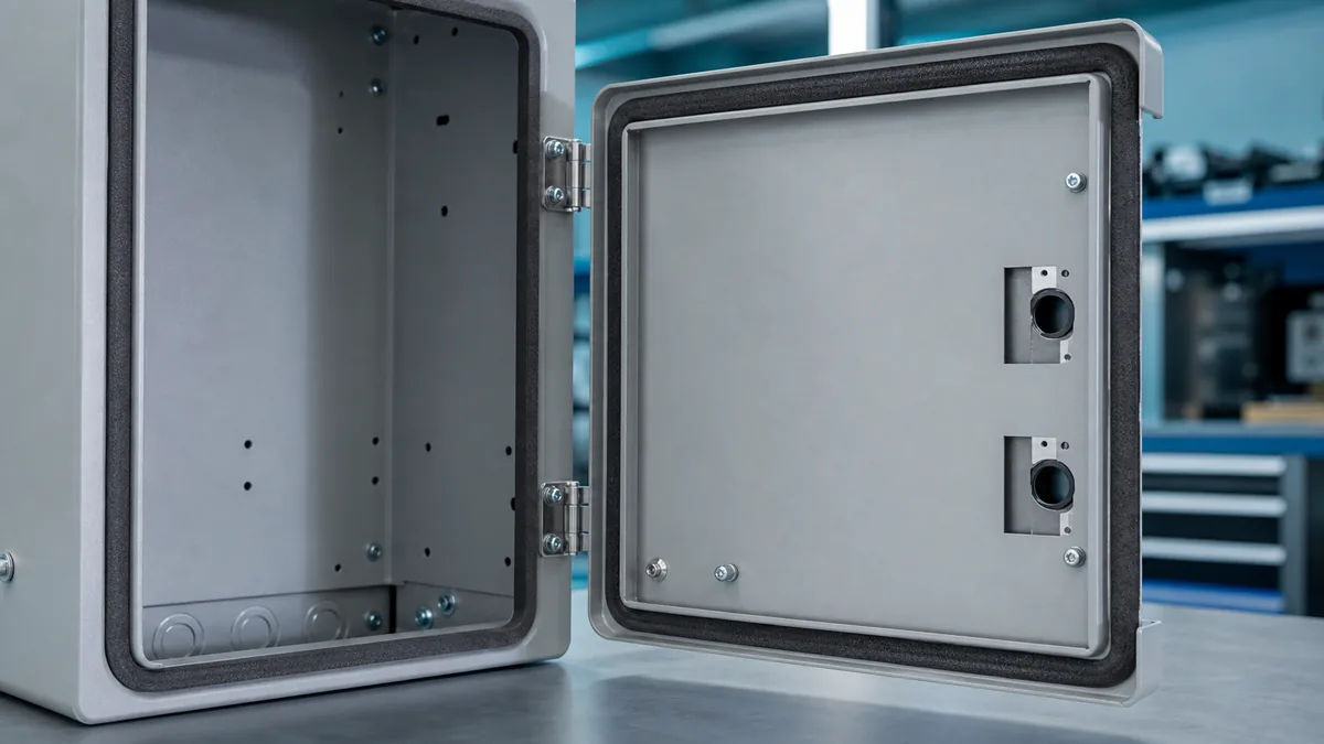
Shop-controlled geometry
The released drawing should define door flatness, seal land, corners, seams, hinge axis, latch locations, drains and finish allowance. MSTFAB can record agreed dimensions and fit checks on the empty shell.
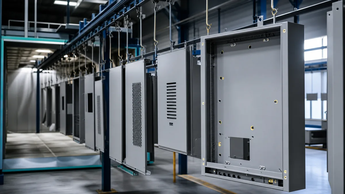
Project-specific finish
Material, pretreatment, coating layers, color, texture, film thickness, masking and repair criteria should follow the exposure specification. Selected finishing processes may be completed by qualified long-term partners.
Rating boundary: an empty shell alone does not establish an IP or NEMA rating. The assembled configuration and required verification include installed gaskets, glands, vents, cooling hardware and field work. Use the IP65 EV charger sealing and inspection guide for the detailed ingress-control path.
Review the cabinet in every state that can change an interface.
| Cabinet state | What can change | Release or handoff record |
|---|---|---|
| Packed | Doors, loose panels, coated faces, lifting hardware and base edges can move or rub in transit. | Packing method, restraints, loose-part list, orientation and pre-shipment photographs. |
| Lifted | The load path and door opening may see a different condition than when the cabinet stands on its base. | Approved lifting method, mass and center of gravity supplied by the responsible party. |
| Placed and anchored | Foundation flatness, shims, anchor tightening and conduit position can affect base and door alignment. | Installation instructions, anchor sequence, allowable adjustment and site inspection ownership. |
| Cabled and populated | Cable loads, device mass, seals and service paths can affect panels, doors and the outdoor boundary. | Installed-interface checklist and completed-system inspection or test plan. |
| Serviced or changed | Replacement components, new holes, damaged finish or a different gasket can alter the approved baseline. | Change approval, revised drawing, repair method and re-verification decision. |
When a cabinet is tied to a certification project, use the UL 2594 / UL 2202 enclosure baseline and change-control guide to identify which mechanical changes require review by the responsible certification team.
Make the first article answer installation questions, not just drawing dimensions.
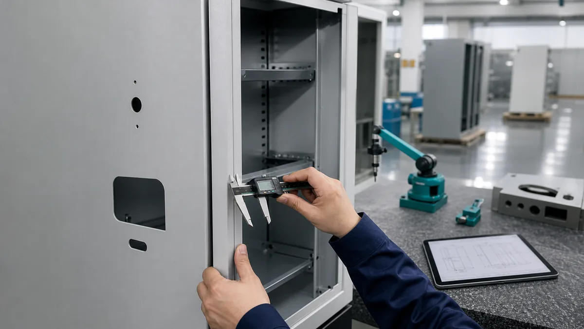
Interface register
List the owner, source file, revision and acceptance method for every site-critical interface.
DFM review
Check base access, cutout reinforcement, cable paths, door swing, drain routes and inspection access.
First article
Record agreed base, anchor, door, panel, cutout, gasket-land and service-clearance characteristics.
Handoff
Identify loose parts, lifting hardware, installation orientation, field-sealing notes and change restrictions.
Repeat release
Resolve deviations and freeze the accepted revision before recurring production begins.
Send the files that connect the cabinet to the site.
MSTFAB does not publish one MOQ, lead time or tolerance for every outdoor cabinet. Those values depend on geometry, material, size, weld sequence, finishing route, hardware, inspection and quantity.
- STEP or STP assembly and controlled 2D PDF
- DXF or DWG data when buyer controlled
- Foundation, anchor and base datums
- Finished grade and drainage assumptions
- Conduit, cable and gland-plate zones
- Installed component interface schedule
- Door swing and service clearances
- Shipping mass and handling method
- Material, finish and exposure inputs
- Inspection, packing, quantity and destination
Outdoor EV cabinet questions to settle before release.
What does MSTFAB supply for an outdoor EV charging cabinet project?
MSTFAB supplies drawing-based fabricated mechanical parts and empty enclosure shells. The approved scope may include cabinet bodies, doors, bases, plinths, mounting plates, gland plates, brackets, rain-control features, drawing-defined hardware, finish coordination, inspection and packing. Charging modules, wiring, cables, controls, payment systems and completed-equipment integration remain buyer controlled.
Who defines the foundation, anchor pattern and site loads?
The buyer, site designer or responsible engineer defines the foundation, anchor reactions, bolt pattern, finished grade, allowable movement, wind or seismic inputs where applicable, conduit locations and site clearances. MSTFAB fabricates the released base and anchor interfaces and verifies the agreed metal geometry.
Can an empty outdoor EV cabinet shell be called IP or NEMA rated?
An empty shell can be fabricated with drawing-defined seams, gasket lands, rain features and equipment interfaces. The completed ingress or enclosure rating depends on the assembled doors, gaskets, glands, vents, cooling hardware, field penetrations, installation orientation and required verification. Final acceptance belongs to the responsible OEM, integrator or test party.
Who owns field-drilled openings and field sealing?
The installer or party authorizing the field change owns the approved location, method, hardware and sealing of field-made penetrations unless the contract states otherwise. Changes that cross the cabinet boundary should be reviewed against the controlled interface schedule before drilling.
Which files and site data should the RFQ include?
Send a STEP or STP assembly with controlled 2D PDF drawings, plus DXF or DWG data when buyer controlled. Include equipment and door loads, foundation and anchor data, conduit and cable zones, finished grade, drainage assumptions, lifting method, service clearances, installed devices, material, finish, inspection, packing, quantity and destination.
Does MSTFAB publish one MOQ, lead time or tolerance for every outdoor cabinet?
No. Quantity feasibility, lead time and tolerances depend on cabinet size, material, geometry, tooling, weld sequence, finishing route, hardware, inspection scope and order volume. They are confirmed from the released drawing package and quotation for each project.
Ready to connect the cabinet drawing to the site?
Send the current assembly, controlled drawings, foundation and cable data, installed-interface schedule, quantities and destination. MSTFAB will review the drawing-based mechanical scope and return project-specific manufacturing questions.
 WeChat Contact
 WhatsApp Me Directly