Quick Answer
A DIN rail can be perfectly straight and still be installed badly. That usually surprises buyers. The rail itself may meet its mechanical specification. The enclosure may meet its overall dimensions. Then final assembly begins and somebody discovers: The DIN rail is too close to the side wall, terminal screws cannot be reached, cable bend space disappears, a bracket flexes when equipment is clipped on, or the rail sits behind a door reinforcement.
For a custom telecom DIN rail enclosure, OEM buyers should freeze at least these mechanical requirements before fabrication: DIN rail type and length, Rail position datum, Rail-to-wall clearance, Rail-to-door clearance, Rail-to-mounting-plate relationship, Rail-support bracket geometry, Bracket stiffness, Rail spacing, Cable bend and routing space, Terminal tool access, Cable-entry relationship, Grounding attachment features, Surface finish and masking, First-article mechanical fit, and Revision control.
MSTFAB provides drawing-based custom sheet metal fabrication.
Our mechanical manufacturing scope may include: Telecom enclosure shells, Doors, Side panels, Mounting plates, DIN rail support brackets, Internal equipment brackets, Removable mounting panels, Gland plates, Cable-entry panels, Internal partitions, Grounding studs, PEM nuts, PEM studs, Rivet nuts, Welded supports, Fan/filter panels, Powder coating, Dimensional inspection, Mechanical first-article checks, and Export packaging.
We do not manufacture the finished telecom system. We do not supply or configure: Routers, Radios, Switches, PLCs, Terminal devices, Power supplies, Batteries, Network software, or Wiring.
The buyer supplies the intelligence. We make sure the metal gives that intelligence somewhere sensible to sit.
Why DIN Rail Problems Usually Appear During Assembly
DIN rail looks simple. It is a strip of metal. That simplicity is dangerous because it encourages engineers to treat rail placement as: Put rail here.
The real interface includes: Rail, Bracket, Enclosure wall, Equipment depth, Cable, Connector, Tool, and Technician. The rail position may therefore be dimensionally correct and still be functionally poor. For example, the buyer installs terminal blocks. They fit. Then the screwdriver cannot reach the terminal screw because the enclosure side wall is too close.
Technically: Rail fits, Terminal fits, Enclosure fits. The electrician remains unhappy. DFM exists in the space between “everything fits” and “everything can actually be assembled.”
1. Specify the DIN Rail Before Designing the Bracket
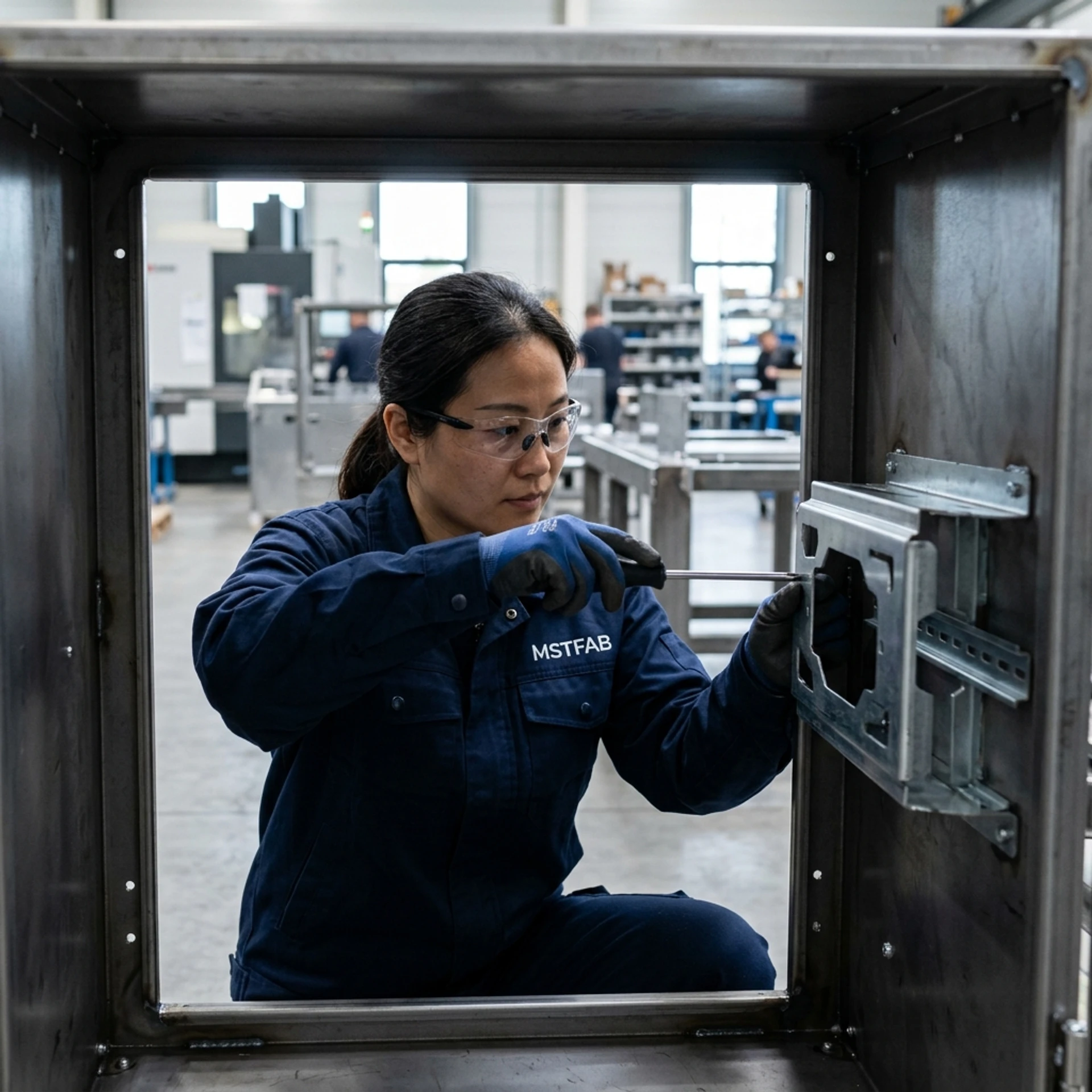
Do not begin with a generic drawing note: Standard DIN rail. Define the intended rail where required. The buyer may specify: Rail profile, Rail width, Rail thickness, Material, Finish, Length, and Hole pattern. MSTFAB can then design or manufacture the supporting sheet metal geometry according to the approved rail interface. The rail itself may be a purchased mechanical component. The support around it is our sheet metal problem.
2. Establish the Rail Datum
The rail should have a clear positional reference. Possible datums include: Mounting plate edge, Enclosure bottom, Internal frame, or Controlled centerline. Avoid rail locations dimensioned through long chains such as: Cabinet edge → bracket → panel → secondary bracket → rail. Each feature can introduce variation. For critical layouts, define the rail relative to the functional assembly datum. A DIN rail should have an address. “Somewhere around the middle” is more of a neighborhood.
3. Design Around the Equipment Envelope, Not Just the Rail
The DIN rail itself occupies little space. The equipment clipped onto it may occupy considerably more. Buyer-installed devices can extend Up, Down, Forward, and Sideways from the rail. Therefore the buyer should provide where relevant: Device mechanical envelope, Connector envelope, Terminal access, and Removal direction. MSTFAB does not need to understand what the device does electrically. We need to know how large it becomes mechanically.
4. Leave Enough Space Above and Below the Rail
Rail-mounted devices often need cable access above or below them. The exact requirement depends on the buyer’s Device, Terminal location, Cable size, Wiring duct, and Service method. Do not use a universal internet clearance number. Establish the actual mechanical envelope. The rail should not be positioned so close to an enclosure flange that the wire can technically reach the terminal only if it first develops a new joint.
5. Tool Access Must Be Treated as Real Geometry
A terminal screw may have adequate clearance for the screw itself. That does not mean a technician can operate it. Consider the actual Screwdriver shaft, Driver handle, Torque tool, Socket, or Test probe where relevant. The tool needs space to approach the device. A screw that exists but cannot be reached is an unusually permanent fastener.
6. Review Rail Position With the Door Closed
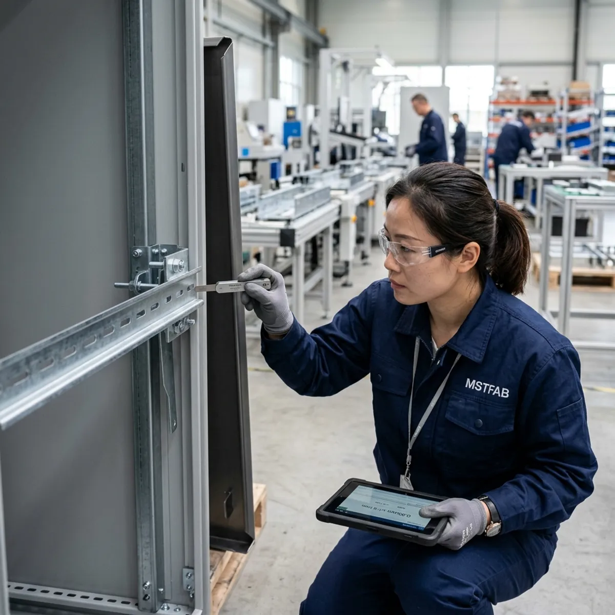
A DIN rail layout often looks excellent when the cabinet door is hidden in CAD. Put the door back. The inside of the door may contain Reinforcement, Latch rods, Locks, or Buyer-defined mechanical hardware. These can reduce usable depth. Check: rail-mounted equipment envelope + cable/tool envelope + door structure together.
7. Door Reinforcement Can Steal Internal Depth
Large telecom enclosure doors may use Folded returns, Hat-section stiffeners, or Welded reinforcement. These improve door stiffness. They also occupy internal space. If DIN rail equipment is positioned close to the front of the cabinet, review Door stiffener, Lock mechanism, and Equipment projection before fabrication. A reinforcement section can solve door flatness beautifully while creating a new equipment collision.
8. Rail-Support Brackets Need Stiffness
A rail mounted on a flexible bracket may move when Devices are clipped on, Wires are inserted, Terminal screws are tightened, or Maintenance is performed. Depending on geometry, bracket stiffness may be improved through Sheet thickness, Formed return, Channel geometry, Shorter unsupported span, or Additional mounting point. Do not automatically make the entire bracket from heavy plate. A simple bend can often add significant stiffness.
9. Long Rails Need More Than Two Optimistic Support Points
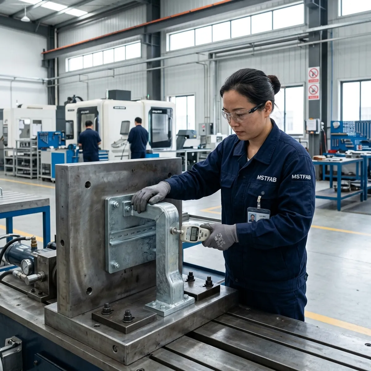
A long DIN rail carrying multiple mechanical devices may require appropriate support spacing. The exact design depends on Rail length, Device load, Bracket geometry, and Enclosure environment. Do not assume two end fasteners are always enough. Likewise, do not add ten brackets without a reason.
10. Check Rail Straightness in the Installed Condition
A DIN rail can be straight before installation. Then a distorted mounting surface can force it into another shape. Possible causes include Warped mounting plate, Misaligned support brackets, Weld distortion, or Uneven fastener seating. For critical first articles, inspect the installed rail condition, not only the loose rail.
11. Parallel Rails Need a Common Datum
Some telecom enclosure layouts use several parallel DIN rails. If each rail is dimensioned independently from different local features, spacing variation can accumulate. Where functional, use a Common datum, Controlled vertical spacing, and Controlled bracket pattern. Parallel rails should ideally remain parallel.
12. Do Not Weld Near Critical Rail Locations Without Reviewing Distortion
Welding internal support brackets can move geometry. Possible effects include Rail bracket shift, Panel bow, and Rail-angle change. If rail position matters to the buyer’s assembly, inspect the critical bracket after welding. Do not rely only on laser-cut hole accuracy. The laser may have performed perfectly. Then welding entered the meeting.
13. Use Fixtures Where Repeat Rail Position Matters
For repeat telecom enclosure production, a simple fixture can help control Bracket location, Rail spacing, and Bracket angle. This is especially useful when several welded internal supports must align. A fixture should control the functional geometry. It does not need to hold every dimension in the enclosure hostage.
14. Rail Position and Cable Entry Must Be Reviewed Together
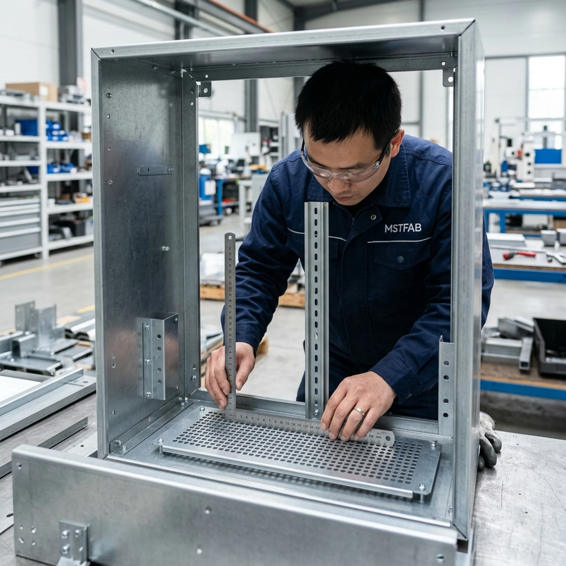
Telecom cabinets often include cable entry through Bottom gland plate, Rear opening, or Side entry. A rail located directly above the entry may create Tight cable bends, Blocked glands, or Difficult terminal access. Review the route: cable entry → bend → routing space → rail-mounted device as one mechanical path. For detailed routing solutions, review our enclosure cable entry DFM article.
15. Leave Room for Cable Bending
Large or stiff cables require physical space to change direction. The buyer should provide the actual cable or connector envelope where this is important. Do not dimension only Cable outside diameter if the cable has Connector, Gland, or Strain relief already attached. A 12 mm cable can arrive with a connector considerably less committed to being 12 mm.
16. Wiring Duct Needs Its Own Mechanical Space
Many internal layouts include DIN rail, Wiring duct, and Cable-support brackets. These should not be positioned independently. Check Rail-to-duct spacing, Duct-cover removal, Fastener access, and Cable exit direction. A wiring-duct cover that cannot be removed because the DIN rail sits too close has still technically been designed as removable. The word is doing a lot of work.
17. Mounting Plate and DIN Rail Should Use the Same Interface Logic
Some DIN rails mount Directly on a mounting plate, On formed brackets, or On removable internal plates. Each has different tolerance behavior. If the rail is attached to a removable mounting plate, check Plate flatness, Rail position, and Mounting-plate locating strategy. For broader mechanical assembly principles, see our DIN rail and internal enclosure layout guide.
18. Removable Rail Panels Need an Installation Path
A removable rail panel may be useful where the buyer wants Bench assembly, Faster service, or Modular variants. But review Panel insertion, Panel removal, Fastener access, and Cable clearance. The panel may fit once installed. The more interesting question is how it got there. CAD occasionally teleports components. Factory technicians generally request another method.
19. Avoid Rail Brackets That Block Service
A bracket can be structurally excellent and positioned exactly where a terminal or connector must be serviced. Overlay: Bracket, Device, Connector, and Tool envelope in the same assembly. Internal enclosure space is shared real estate. Every new piece of steel should justify its tenancy.
20. Grounding Features Need Separate Mechanical Definition
DIN rails can sometimes participate in electrical bonding strategies depending on the buyer’s system and component design. The buyer should specify required Grounding stud, Bonding attachment, Bare-metal contact area, and Rail attachment method where applicable. A steel rail is conductive. That does not automatically make it the electrical engineer.
21. Powder Coating Changes Mechanical Interfaces
Powder coating can affect Threaded holes, PEM hardware, Rail mounting surfaces, and Bracket fit. Use project-specific controls such as Thread masking, Contact-area masking, and Clearance allowance where required. A masking drawing should answer questions before the coating operator develops philosophical interest in them.
22. Not Every Rail Mounting Surface Should Be Bare
Bare-metal areas should exist for a reason, such as Electrical bonding or Specific mechanical fit. Leaving unnecessary areas uncoated can introduce Corrosion exposure and Appearance inconsistency. Uncontrolled bare steel is just unfinished steel wearing a technical explanation.
23. Threads Need Final Inspection After Coating
If the rail bracket uses PEM nuts, Rivet nuts, Tapped holes, or Weld nuts, critical threads should remain usable after finishing. Do not consider the hardware approved only because the screw worked before powder coating. That was the rehearsal.
24. Rail Brackets Near Bends Need Tooling Review
A rail mounting hole or PEM fastener positioned close to a formed flange may create manufacturing problems like Press-brake tooling conflicts or Hardware insertion tooling obstruction. Review Hole-to-bend relationship and Hardware installation sequence. Production knows chronology.
25. Internal Brackets Should Not Create Sharp Cable Edges
Cable-routing areas should avoid unintended Sharp edges, Burrs, and Unfinished cutouts according to buyer workmanship requirements. MSTFAB can Deburr, Edge-finish, or Form protective returns where specified. The enclosure should avoid behaving like a cable stripper.
26. Telecom Enclosures Often Need Variant Control
One telecom enclosure family may use Different DIN rail lengths, Different bracket positions, and Different mounting plates. Give variants controlled Part numbers, Revisions, and BOMs. Do not identify them as: long rail version, short rail version.
27. Standardize the Cabinet, Vary the Internal Rail Module Where Practical
For product families, OEMs may be able to keep one cabinet shell while changing Removable rail plate, Rail bracket module, or Internal mounting panel. But modularity must remain mechanically controlled. A “universal” internal plate containing every hole from every historical customer is not modular. It is archaeology with powder coating.
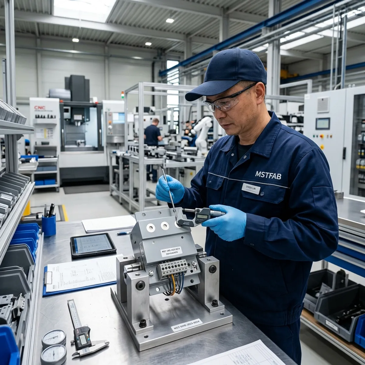
28. First Article Should Include the Rail Assembly
For new telecom enclosure projects, do not inspect only Empty cabinet, Loose rail, or Loose bracket. Install the mechanical rail assembly. Verify Rail position, Rail straightness, Parallel spacing, Bracket stiffness, Hardware, Door clearance, Cable-entry relationship, and Tool space. The shell can complete its mechanical exam without internet access.
29. Use Dummy Devices or Mechanical Templates
For critical layouts, the buyer may provide Actual nonfunctional sample, 3D-printed dummy, Mechanical block, or Checking template representing the mounted equipment envelope. This can verify Rail location, Depth, Terminal access, and Cable clearance without sending expensive electronics to the fabrication floor.
30. Inspect the Finished Condition
Where coating or welded supports affect rail fit, conduct the meaningful first-article check after the intended production process. Checking only the flat plate is useful. Checking the completed interface is useful to the customer.
31. Define DIN Rail CTQs
For repeat OEM programs, identify which dimensions are critical. Possible CTQs include Rail vertical position, Rail-to-rail spacing, Rail-to-cable-entry clearance, Support-bracket location, and Mounting-panel datum. Numbers do not become important simply by becoming smaller.
32. Use Go/No-Go Fixtures for Stable Repeat Programs
For repeat production, a simple fixture may confirm Rail position, Bracket pattern, and Multiple-rail spacing quickly. Quality control occasionally benefits from asking simple questions.
33. DIN Rail Alignment Is Only One Telecom Enclosure Interface
This article deliberately stays narrow. Its job is specifically DIN rail mechanical support inside custom telecom enclosure shells. A page trying to rank for every type of metal inside a telecom cabinet eventually becomes a brochure. Buyers already have brochures. They need answers.
34. ISO 9001 Supports Process Control—It Does Not Certify the DIN Rail Enclosure
ISO 9001 is a quality-management-system standard. It does not by itself determine Rail position, Rail spacing, Service clearance, Cable bend space, or Bracket thickness. Those requirements must come from the drawing and project specification. Certificates are useful. Rail brackets that fit are useful too. Buyers tend to appreciate both.
35. Keep ISO 9001 Version Language Maintainable
As of August 2026, ISO 9001:2015 remains the current published edition, while a new edition is approaching publication. The buyer’s mechanical problem remains: Will the rail be in the right place?
36. Galvanized Steel Is an Option, Not the Entire Strategy
Galvanized or zinc-coated steel can be appropriate depending on Environment, Corrosion requirement, Finish, and Cost. But not every telecom enclosure needs the same material. Select material based on the actual project. Google does not have to bend the part.
37. Do Not Automatically Specify Hot-Dip Galvanizing
Thin precision DIN-rail support brackets and enclosure panels may have different finish requirements from heavy structural steel. “Galvanized” is not one manufacturing process. It is a conversation starter.
What MSTFAB Manufactures
MSTFAB provides custom sheet metal fabrication from OEM drawings.
For telecom enclosure projects, our mechanical scope may include: Enclosure shells, Doors, Side panels, Mounting plates, DIN rail brackets, Rail support panels, Internal partitions, Gland plates, Cable-entry panels, Grounding attachment features, PEM hardware, Reinforcement, Fan/filter panels, Base frames, Powder coating, Dimensional inspection, Mechanical first-article checks, and Export packaging.
We do not supply: Network switches, Routers, Radios, Telecom power electronics, Batteries, PLCs, Wiring, Software, or Complete telecom equipment.
We manufacture the physical metal architecture. The customer decides what communicates. We make sure it has enough room to do so.
Responsibility Matrix
| Project Item | MSTFAB Sheet Metal Scope | Buyer / Telecom OEM Scope |
|---|---|---|
| Enclosure body | Fabricate | Define envelope |
| DIN rail brackets | Fabricate | Define required location/load |
| Rail support panel | Fabricate | Define equipment layout |
| Rail installation | Install if in agreed scope | Approve rail specification |
| Mounting plate | Fabricate | Define mounted equipment |
| Cable-entry plate | Fabricate | Define cables/connectors |
| Grounding studs | Fabricate mechanically | Define electrical function |
| Surface finish | Apply to specification | Define environmental requirement |
| Thread masking | Apply as drawing requires | Define functional interfaces |
| Mechanical FAI | Perform agreed checks | Define CTQs |
| Telecom equipment & Wiring | Not supplied | Buyer/integrator |
Key Takeaways
A telecom DIN rail enclosure should be designed around the complete mechanical installation interface, not only the rail itself. The cheapest time to discover that a terminal screwdriver cannot reach the DIN rail is during the 3D DFM review.
The expensive version begins after the enclosure has been shipped overseas, installed in a telecom site, filled with devices, and the technician discovers that the only way to tighten one terminal is to remove everything installed beside it. At that moment, 15 millimetres of extra clearance becomes the most valuable real estate in telecommunications.
Custom Telecom Enclosure Fabrication
MSTFAB manufactures precision telecom cabinet shells, mounting plates, DIN rail brackets, and mechanical interfaces designed for reliable field service and rapid assembly.
 WeChat Contact
 WhatsApp Me Directly