BUILD-TO-PRINT GALVANIZED ENCLOSURE METALWORK
Quick answer: galvanized terminal box shell DFM should freeze the DIN-rail datums, cable-entry zones, cover fit, gasket or overlap path, zinc-coated material, weld route and first-article checks before production. MSTFAB fabricates the buyer-defined empty shell and mechanical parts. We do not supply a wired terminal box, select electrical devices, perform energized testing or certify the completed equipment.
Buyer shortcut: put the material and finish requirements in the galvanized enclosure RFQ specification, then tie reportable dimensions to the first-article inspection plan. That keeps the approved drawing, quotation and receiving inspection on the same page.

1. Start with the word “shell”
A terminal box shell is the fabricated metal housing before terminal blocks, wires, glands, labels and electrical accessories are installed. It may include a body, cover, mounting plate, blank gland plate, brackets, studs and drawing-defined hardware.
Empty bodies, covers, blank panels, mechanical mounting provisions, brackets, cutouts, welded studs, specified inserts, finishing, dimensional inspection and export packing.
Terminal blocks, cables, glands, wiring, circuit protection, energized testing, commissioning and certification of the finished electrical product.
Electrical architecture, selected devices, cable system, bonding design, sealing concept, ratings, final assembly, testing and product certification.
This is not a small wording detail. Calling an empty shell a complete terminal box is how an RFQ quietly acquires components, standards and liabilities that were never in the metal shop’s quotation.
2. Send the assembly relationship, not only six flat DXFs
The body, cover, DIN-rail provision, cable-entry area and mating equipment belong to one mechanical relationship. Supply the assembly model so the fabricator can see access, clearances and installation direction, then use controlled 2D drawings to define measurable requirements.
- Assembly STEP file
- Controlled shell and cover drawings
- Material grade and zinc system
- Sheet thickness and coating requirement
- Functional datums and tolerances
- DIN-rail or bracket interface
- Cable-entry keep-out zones
- Cover fastener and access details
- Weld and edge-treatment notes
- Masking or contact-area requirements
- Inspection and FAI needs
- Part numbers, revisions and quantity

3. Define the galvanized material precisely
“Galvanized steel” can describe several different zinc-coated products and processes. Pre-galvanized sheet, electrogalvanized sheet and post-fabrication hot-dip galvanizing are not interchangeable. They differ in coating thickness, appearance, edge protection, forming behavior, weld response and dimensional effect.
State the base steel, coating designation or mass, exposed-edge requirement and any approved repair method. MSTFAB manufactures to the confirmed drawing and process route; the buyer approves the material system for the final environment.
Practical rule: “galvanized” is a material-system input, not a complete corrosion specification.

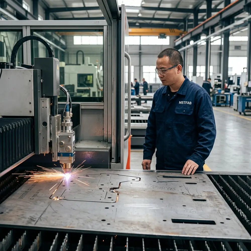
4. Decide what happens at laser-cut edges
Laser cutting exposes base metal along holes and profiles. The zinc coating beside the edge may provide some sacrificial protection, but performance depends on material, edge geometry and environment. Do not assume every cut edge automatically satisfies the product’s corrosion target.
Define whether edges remain as cut, receive an approved zinc-rich repair, are covered by another finish or require a different process. Small cable openings and slots also need deburring requirements because cable jackets are not enthusiastic about sharp surprises.
5. Control bending without turning the zinc surface into a diary
Bending can mark, polish or locally change the coating appearance. Review inside radius, flange length, bend relief, grain direction where relevant and tool-contact surfaces. Cosmetic faces should be marked on the drawing.
For small boxes, several bends interact. A slight angle change can move the cover flange, DIN-rail seat and gland plate opening at the same time. Inspect functional offsets in the formed condition rather than admiring each bend in isolation.

6. Keep welding local, controlled and honest
Welding can burn the zinc layer, create fumes, distort thin panels and leave areas that need an agreed restoration method. Define weld type, length, location, cosmetic expectation and post-weld treatment. Where tabs, clinching, riveting or formed construction can meet the mechanical need, review them as DFM options rather than welding by reflex.
Small galvanized enclosures are particularly sensitive to heat and restraint. The related galvanized enclosure weld-distortion DFM guide covers fixture datums, sequence and DIN-rail integration in more detail.
7. Define the DIN-rail mounting interface from stable datums
MSTFAB can fabricate buyer-defined holes, studs, brackets or mounting seats for later rail installation. The buyer specifies the rail system, terminal-block envelope, load and required clearances.
Locate mounting features from stable shell datums. Check rail length, end-stop allowance, screwdriver access, terminal-block height, wire-bend space and cover clearance. A DIN rail that fits only before the terminals arrive is a very accurate shelf.

8. Reserve cable-entry zones before adding brackets
Define cable-entry faces, blank gland plates, connector cutouts and no-feature zones in the assembly model. Include gland-body size, locknut access, cable bend radius and separation requirements owned by the buyer’s electrical design.
When the exact field entry is not frozen, a removable blank plate can preserve flexibility. Its opening, fasteners, edge condition and gasket concept still need controlled geometry. “Installer will drill something somewhere” is flexible, but not in the useful engineering sense.
9. Check cover fit in the finished shell condition
A removable cover depends on body squareness, flange position, fastener alignment and coating or zinc buildup. Define the locating method, gap, overlap, screw type, insertion direction and tool access.
If the buyer expects a gasket or environmental rating, provide the gasket geometry, compression target, corner condition and approved verification plan. An empty shell does not inherit an IP rating because the product page used the word outdoor.
10. Separate mounting clearance from electrical clearance
MSTFAB can inspect mechanical distances such as rail-to-cover space, bracket offsets and fastener access. Electrical creepage, clearance, temperature rise and component spacing remain part of the buyer’s complete electrical design.
Put buyer-defined keep-out zones into the assembly model. That gives the metal shop measurable geometry without asking it to approve a circuit it does not design or assemble.
11. Plan hardware and tool access in the real sequence
Self-clinching nuts, rivet nuts, weld studs and captive screws need the correct hole, sheet thickness, installation side and tool access. Review whether hardware is installed before or after forming and whether nearby flanges block the installation press.
Fastener substitutions require approval when they change hole size, projection, finish or installation method. The same thread is not the same interface wearing a different hat.
12. Identify contact areas without claiming a finished bonding system
If the buyer requires bare contact pads, grounding studs or masked regions, show their mechanical geometry and finish condition on the drawing. MSTFAB can fabricate and inspect those specified features.
The buyer or qualified integrator remains responsible for conductor selection, bonding design, electrical continuity testing and certification of the assembled equipment.
13. Control part identity and revisions
Terminal box families often contain shells that differ by one gland opening, rail pattern or cover hole. Use unique part numbers and visible revision control. Connect the drawing, inspection record, label and packing list to the same identity.
Do not call them “the version with two extra holes.” That naming convention works until the two extra holes are on the wrong wall.

14. Agree on first-article evidence before volume production
| Feature | Useful control | Evidence |
|---|---|---|
| Material system | Base steel and zinc designation | Material certificate or agreed traceability record |
| DIN-rail provision | Functional shell datums | Dimensional report or approved template |
| Cable-entry zone | Finished opening and keep-out | Dimensional and edge-condition check |
| Cover relationship | Gap, overlap and fastener alignment | Assembly trial and visual record |
| Finished surface | Cut-edge, weld and cosmetic criteria | Final visual inspection |
15. Use a responsibility matrix before quotation
| Item | MSTFAB mechanical scope | Buyer or integrator scope |
|---|---|---|
| Body, cover and blank panels | Fabricate to released drawings | Approve geometry and intended use |
| Rail and component provisions | Manufacture specified holes, studs and brackets | Define component envelopes, loads and clearances |
| Electrical components | Not selected, supplied or wired | Select, install and validate |
| Environmental performance | Build buyer-defined shell geometry | Define gasket, cable entries and final rating tests |
| Finished product certification | Provide agreed mechanical records | Own electrical testing and certification |
16. Pack the inspected condition, not just the part
Galvanized surfaces can scratch during nested transport. Covers, studs and finished edges need separation and restraint. Define whether covers ship assembled, loosely attached or separately wrapped, and link package labels to the part revision.
The final inspection report is not much comfort if the cover spends the journey polishing the shell beside it.

17. RFQ checklist
- Assembly STEP model
- Controlled body and cover drawings
- Material and zinc-coating designation
- Finished sheet thickness
- Cut-edge and weld-restoration notes
- Functional datums and tolerances
- DIN-rail mounting provisions
- Cable-entry zones and blank plates
- Cover fasteners and access
- Masking or contact areas
- FAI and inspection documentation
- Quantity, revision and delivery destination
Choose the enclosure target before release: use the NEMA 12 galvanized terminal box guide for indoor dust, drip and cable-entry planning, or the NEMA 4X galvanized terminal box guide for washdown, outdoor exposure and corrosion decisions.
Frequently asked questions
Does MSTFAB supply a complete wired terminal box?
No. MSTFAB fabricates buyer-designed empty galvanized sheet metal shells and mechanical parts. The buyer or integrator installs terminals, glands, wiring and electrical devices.
Is galvanized steel suitable for every environment?
No. Suitability depends on the zinc system, cut edges, weld treatment, exposure and buyer-defined corrosion requirements. The final material system must match the actual environment.
Can MSTFAB provide DIN-rail mounting features?
Yes, when the buyer drawing defines the holes, studs, brackets, datums and tolerances. Electrical components and final integration remain outside MSTFAB’s scope.
Does an empty shell automatically have an IP rating?
No. Final protection depends on the complete enclosure, gasket, fasteners, cable entries, assembly process and verification test defined by the product owner.
Send the empty-shell interface, not an electrical shopping list
Share the assembly model, controlled drawings, galvanized material requirement, quantity, cable-entry zones and critical inspection points. MSTFAB will review the build-to-print shell and return practical DFM questions before production.
 WeChat Contact
 WhatsApp Me Directly