Medical Equipment Enclosures | Mechanical Interface DFM
A connector panel is where the enclosure, connector, cable, service tool and product configuration all meet. This guide shows OEM buyers what to release before a seemingly simple cutout becomes an assembly delay.

Quick Answer
Medical enclosure connector panel DFM should control the complete mechanical interface: exact connector identity, finished panel thickness, cutout and mounting pattern, front and rear envelopes, mating plug, cable boot, bend radius, hand and tool access, strain relief, coating, service removal and first-article evidence.
A cutout can be dimensionally correct and still fail. The connector body may hit a return flange, the locking ring may have no finger clearance, the cable may bend into a bracket, or the finished coating may close a tight opening. Release the interface as an assembly, then inspect the fabricated metalwork against that released condition.
Six Decisions That Control the Panel
The useful DFM conversation follows the connector from the drawing to service access.
Keep the Responsibility Boundary Honest
The OEM owns the medical device and electrical interface. MSTFAB manufactures the drawing-defined metal components. A quality-system certificate does not move product-design responsibility to the sheet-metal supplier.
MSTFAB fabrication scope
- Rear panels and removable I/O plates
- Connector cutouts and mounting-hole patterns
- Returns, stiffeners, brackets and cable-support features
- Drawing-defined inserts, studs and mechanical hardware
- Specified surface finishing and masking
- Dimensional inspection and agreed mechanical trial fit
OEM or integrator scope
- Connector selection and approved alternatives
- Signal, power, EMC and electrical architecture
- Creepage, clearance, bonding and leakage-current design
- Sealing, cable loads and strain-relief validation
- Risk management, usability and service procedures
- Completed-device testing, regulatory submission and market compliance
1. Freeze the Exact Connector Interface
Start with the manufacturer, complete part number, approved drawing revision and alternative-part rules. Similar connectors in one family can use different panel thickness ranges, anti-rotation features, mounting ears, latches or backshells.
Transfer the approved geometry into the enclosure drawing. Do not ask the fabricator to choose among catalog PDFs found online. That turns configuration control into a search exercise, and search results are not an engineering change process.

Release package
- Connector manufacturer and part number
- Approved mechanical drawing revision
- Finished panel-thickness range
- Cutout, holes and anti-rotation features
- Approved alternative or no-substitution rule
- Datum and inspection requirements
2. Dimension From Functional Datums
Connector arrays should share datums tied to the enclosure assembly, mounting plate or mating equipment. Independent dimension chains from nearby edges create stack-ups that are difficult to measure and even harder to explain after the cable harness arrives.
Define the cutout size, internal corner radius, mounting holes, countersink or counterbore, positional tolerance and inspection condition. State whether acceptance applies before or after finishing. If a small hole, reamed location or thread needs a secondary process, put it in the route instead of hoping the laser behaves like every tool in the factory.
| Interface Characteristic | Buyer-Controlled Input | DFM / Inspection Evidence | Failure Prevented |
|---|---|---|---|
| Connector cutout | Nominal size, corner radius, tolerance and finished condition | Datum-based dimensional result or controlled gauge | Connector does not seat or rotates in the panel |
| Mounting pattern | Hole size, position, fastener and countersink details | Measured hole relationship and trial assembly | Fasteners bind or flange sits unevenly |
| Panel thickness | Base material plus finish and connector acceptance range | Material record and finished-fit check | Clips, nuts or seals cannot engage correctly |
| Rear envelope | Body, nut, backshell, boot and cable keep-outs | Assembly-model review and representative fit check | Collision with flanges, brackets or internal parts |
| Service envelope | Hand, tool, latch and removal path | Tool-access and removal demonstration | Connector fits once but cannot be serviced |
| Finish and mask | Coating, bare zones, thread protection and appearance | Masking record, visual check and after-finish dimensions | Blocked threads, poor seating or unintended bare metal |
3. Model the Mated Connector, Cable and Service Tool
The connector body behind the panel is only half the story. Include the mating plug, locking ring, release tab, backshell, boot and the first controlled cable section. Evaluate installation and removal paths, not just the final parked position.

Right-angle connectors need directional clearance. Locking rings need finger or wrench space. Release tabs need a path. Cable boots need room to bend without rubbing a sharp edge or neighboring port. Labels should remain visible after the connectors are mated.
If unplugging connector A requires removing connectors B through F, the layout is technically dense and practically annoying. Service access belongs in the interface model before the panel reaches production.
4. Check Bends, Hardware and Assembly Sequence
A cutout close to a bend can distort during forming. A connector nut beside a deep return may fit in CAD but leave no access for fingers or a socket. Self-clinching hardware can compete with press-brake tooling or land too close to an opening.
Review material, thickness, bend radius, flange length, hardware, connector installation direction and tool access together. For detailed insert and stud rules, use the medical enclosure PEM hardware DFM guide.
5. Decide Between a Fixed Panel and Removable I/O Plate
Fixed rear panel
Useful when: the connector set is stable and direct enclosure stiffness matters.
Control: bend access, coating route, cutout revision, internal service space and enclosure-level rework risk.
Removable I/O plate
Useful when: variants, separate finishing, replacement or service access justify another part.
Control: locating method, flatness, gasket or contact face, fastener access, labeling and tolerance stack.

A removable plate should not locate only through loose screw clearance. Use controlled tabs, pilots, shoulders or another drawing-defined location strategy. Check the installation sequence after the rest of the enclosure is assembled. The nearby medical enclosure service-path guide covers similar removal and maintenance risks for internal plates.
6. Protect the Connector From Cable Loads
The OEM defines cable load, routing, clamp type, bend radius and electrical requirements. MSTFAB can fabricate the specified strain-relief bracket, welded stud, clamp pattern or support feature that transfers those loads into the metal structure.

Check bracket stiffness, attachment, tool access, cable bend space and service removal. The bracket should support the cable without trapping it against sharp edges or blocking the connector latch. “The cable will probably find a route” is not a routing requirement.
7. Specify Finish, Masking and Contact Zones
Powder coating and other finishes change opening size, thread condition and contact surfaces. Define whether connector dimensions apply before or after finish. Mask only the areas that require a controlled fit, conductive contact, gasket surface or protected thread.
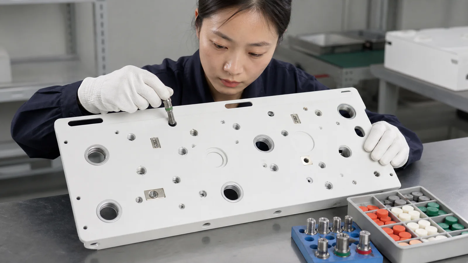
Do not automatically mask every connector opening. Unnecessary bare metal can create corrosion and cosmetic concerns. The OEM defines electrical bonding and sealing intent. For interfaces that form part of a protective-earth path, use the dedicated protective-earth stud and masking guide.
8. First Article Inspection Should Prove the Real Interface
Measure the cutout, mounting pattern, datum relationship, panel flatness and finish condition. Then perform a mechanical trial fit using the approved connector, a controlled sample or a buyer-approved gauge. Include the mating envelope and service tool when they are part of the agreed acceptance scope.

Part number, drawing revision, characteristic, tolerance, actual result, method and disposition.
Approved connector identity, buyer-supplied sample or gauge number and condition.
Useful photographs that support the result without replacing the measured data.
The wider medical enclosure supplier quality handoff guide explains revision, FAI and approved-change ownership beyond this connector-panel interface.
9. Treat Connector Substitution as a Change
A connector substitution can change the cutout, panel-thickness range, anti-rotation feature, mounting hardware, rear depth, mating envelope and service tool. Update the connector list, assembly model, panel drawing, inspection plan and approved sample together.
Prototype handwork must return to CAD before production release. If a technician files one opening to make the sample fit, the drawing needs the lesson. The operator’s memory is not a revision-controlled manufacturing document.
Buyer Trust Table: What Evidence Should Exist?
| Buyer Question | Weak Answer | Useful Evidence | Owner |
|---|---|---|---|
| Which connector controls the cutout? | “A standard circular connector.” | Manufacturer, part number and approved drawing revision | OEM / integrator |
| Will it fit after coating? | “The laser is accurate.” | Finished-condition tolerance and production-intent trial fit | Shared input and verification |
| Can the connector be serviced? | “There is space in CAD.” | Mated envelope, tool path and removal demonstration | OEM defines; supplier reviews metal interface |
| How are cable loads handled? | “The connector is strong.” | Defined cable load, clamp concept and drawing-controlled bracket | OEM validates; supplier fabricates |
| What happens after substitution? | “It is the equivalent model.” | Approved change, updated model/drawing and reinspection trigger | OEM approval plus supplier control |
| Does ISO 13485 prove fit? | “The factory is certified.” | Controlled drawing, inspection record and actual interface result | Supplier QMS and part evidence are separate |
What to Send With the RFQ
Geometry package
- STEP/STP enclosure and connector-envelope models
- Released PDF panel drawing and revision
- Connector drawings and approved alternatives
- Material, thickness, finish and masking
- Brackets, inserts and removable-plate details
Acceptance package
- Critical dimensions and functional datums
- Trial-fit sample or controlled gauge
- Tool, cable and service keep-outs
- FAI and record requirements
- Prototype, batch and annual quantities
Red Flags
Key Takeaways
- Release the exact connector and drawing revision.
- Dimension cutouts from functional datums.
- Model the complete mated and service envelope.
- Check bend, hardware and tool access together.
- Use removable plates only when they solve a real variant or service problem.
- Define cable support without shifting load-validation responsibility.
- Inspect finished openings, masking and threads.
- Use production-intent FAI and controlled fit items.
Frequently Asked Questions
Does MSTFAB select medical connectors?
No. The OEM supplies the approved connector identity, mechanical interface and alternative-part rules. MSTFAB manufactures the released sheet-metal geometry.
Can MSTFAB trial fit a real connector?
Yes, when the buyer supplies an approved sample or controlled gauge and defines the mechanical acceptance condition. The fit check does not replace the OEM’s electrical, sealing or completed-device validation.
Should the cutout be inspected before or after coating?
In-process inspection can catch cutting errors early, but final acceptance should address the finished condition whenever coating thickness, masking or thread protection can affect assembly.
Should every connector use a removable I/O plate?
No. A removable plate is useful when it improves variants, service, replacement or separate processing. It also adds locating, fastener, flatness, sealing and tolerance-stack requirements.
Does ISO 13485 certification prove the connector panel conforms?
No. ISO 13485 concerns the quality management system. Part conformity still requires the controlled drawing, applicable records, inspection results and agreed mechanical trial fit.
Primary Reference Notes
- FDA Quality Management System Regulation — current U.S. medical-device QMS framework, effective February 2, 2026.
- ISO 13485:2016 — official ISO page for medical-device quality management systems.
- IEC 60601-1 consolidated edition — official IEC page for general requirements concerning basic safety and essential performance of medical electrical equipment; the responsible OEM determines applicability.
Send the Connector Envelope With the Panel Drawing
Provide the released rear-panel model, connector references, mating envelopes, finish, strain-relief features, inspection requirements and quantities. MSTFAB will review the empty sheet-metal interface and quote the build-to-print fabrication scope.
Manufacturing scope: Guangzhou Maisituo Sheet Metal Manufacturing Co., Ltd. (MSTFAB) fabricates drawing-defined empty enclosure shells and mechanical components. It does not select the medical connector, assemble the completed device or certify the finished medical equipment.
 WeChat Contact
 WhatsApp Me Directly