OEM BUYER GUIDE · MECHANICAL INTERFACE DFM
Industrial enclosure disconnect handle DFM is not about choosing a red-and-yellow handle from a catalog. It is about making the empty door, shaft axis, support plane and reinforcement geometry match the exact buyer-selected mechanism after cutting, bending, welding and coating.
Quick Answer
Freeze the exact disconnect mechanism and operator family first. Then control the manufacturer drawing revision, door cutout, mounting-hole pattern, shaft centerline, door-to-support depth, adjustment range, reinforcement keep-out, hinge and latch condition, coating state and first-article inspection method.
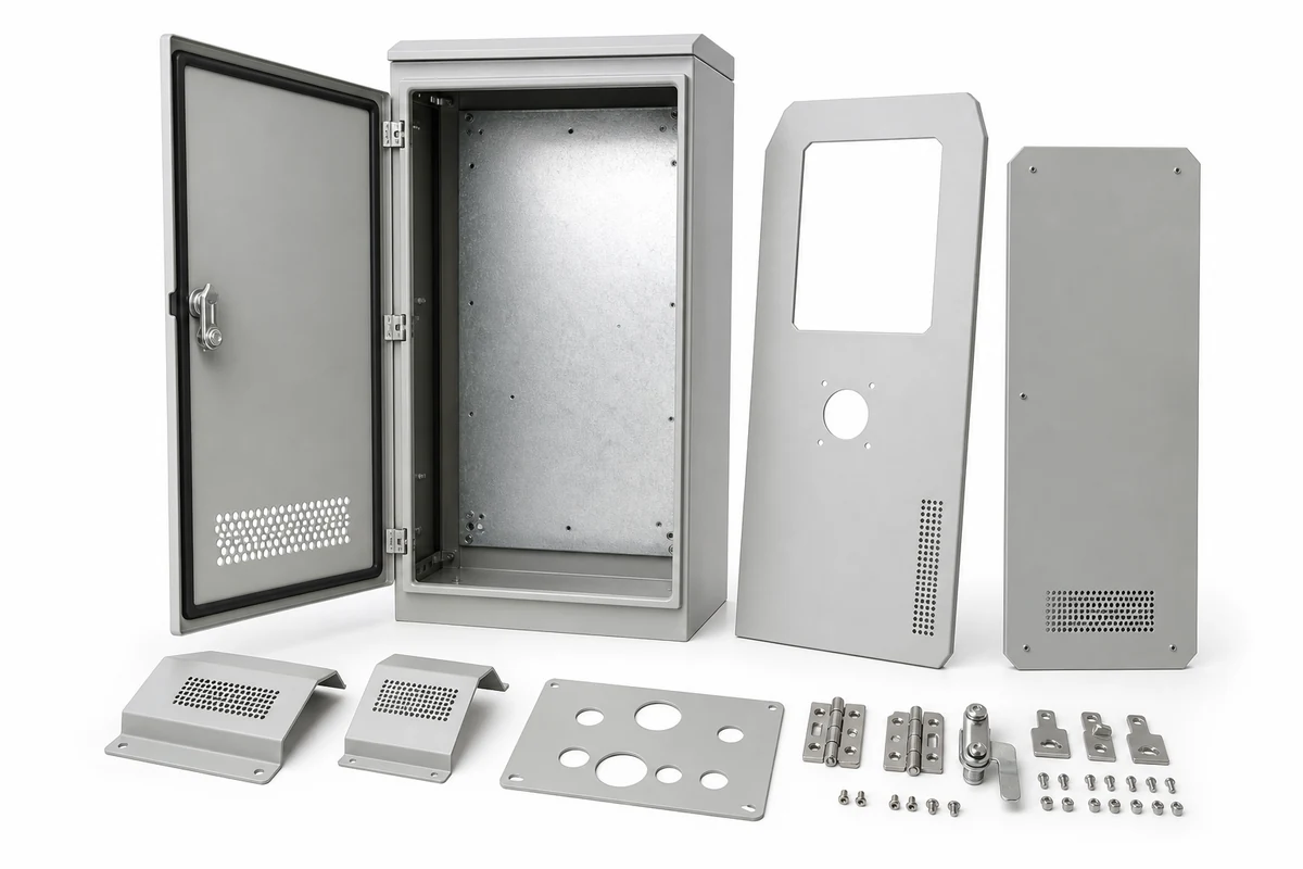
MSTFAB manufactures unpopulated custom sheet metal enclosure shells, doors, mounting plates, brackets and reinforcements from buyer-approved drawings. We do not select or supply the disconnect switch, design the electrical isolation function, wire the panel, adjust the final operating mechanism or certify the completed equipment.
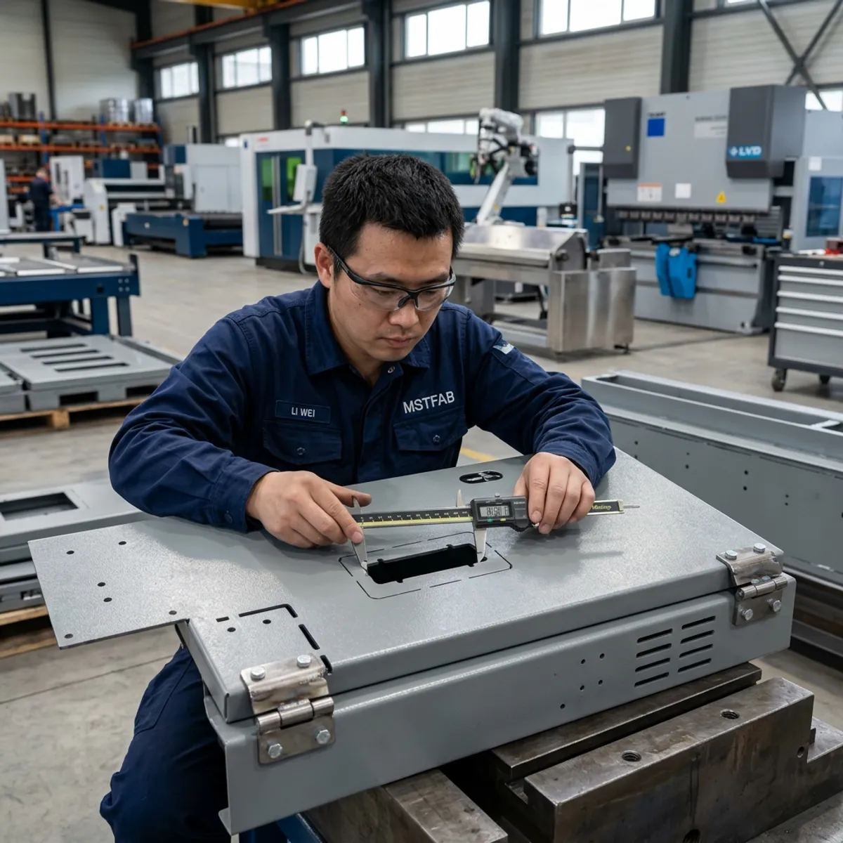
MSTFAB fabrication scope
- Door and enclosure shell fabrication
- Laser-cut operator openings and hole patterns
- Mounting plates, support brackets and stiffeners
- PEM hardware, welding and surface finishing
- Drawing-controlled mechanical inspection
OEM and integrator responsibility
- Select the electrical device and handle family
- Approve interlock, isolation and safety function
- Define electrical clearances and component spacing
- Assemble, adjust and functionally test the mechanism
- Approve compliance and final equipment certification
The Interface Is a Chain, Not One Hole
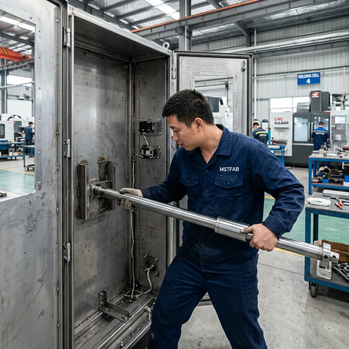
Buyers sometimes send a door drawing with one rectangular cutout and a note that says “disconnect handle here.” That is not yet a controlled interface. The handle may look door-mounted, but its successful operation depends on several parts sharing one mechanical story.
If one link moves, the mechanism may bind, miss engagement or run out of adjustment. The door can still close beautifully while the shaft points at empty air. Sheet metal has a dry sense of humor.
Freeze the Exact Component Family Before Releasing Metal
Different handle and mechanism families can use different cutouts, hole spacing, shaft shapes, coupling depths, door thickness limits and interlock envelopes. A photograph, a generic 3D model or a distributor thumbnail is not enough.
The drawing package should identify the exact manufacturer, part number, accessory combination and current installation document. For example, a device maker may publish a dedicated door-mounted operating mechanism instruction sheet with its own cutout and assembly data. Use the buyer-approved source, such as the applicable manufacturer installation instruction, and record its revision in the project file.
Procurement trap: “Equivalent” is not automatically equivalent
A purchasing substitution can change the door cutout or shaft stack-up even when the electrical ratings appear similar. Do not release substitute hardware until engineering confirms the mechanical envelope. Cheap substitutions have an expensive talent for arriving after the powder coat.
Build a Datum Strategy That Survives Production
Locate the operator cutout and switch support from stable functional datums, not from a chain of folded edges that can accumulate variation. A practical datum plan often begins with the door hinge axis, the finished door plane and a controlled enclosure reference.
Door datum
Controls cutout location, operator mounting and clearance to the door return.
Shaft axis
Connects the door operator to the buyer-defined support bracket or switch plane.
Depth datum
Controls the finished distance after gasket compression, coating and door adjustment.
Dimension the relationship that affects engagement directly. If the shaft center is derived from four unrelated bend dimensions, the tolerance stack is doing more design work than the engineer.

Door Cutout, Hole Pattern and Edge Condition
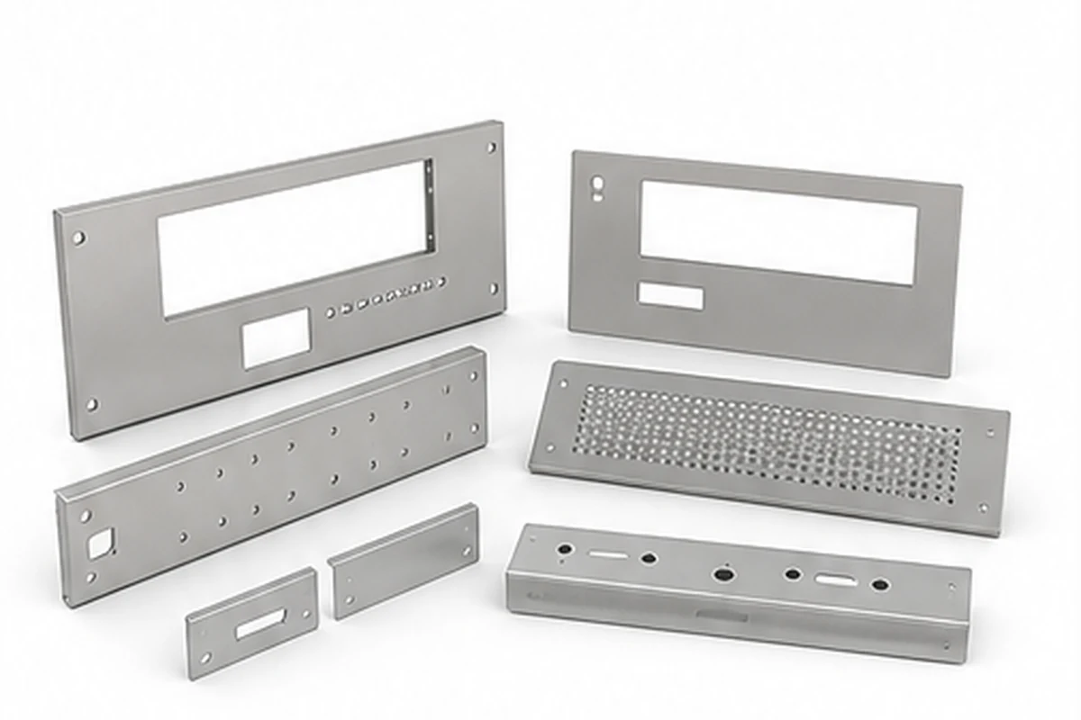
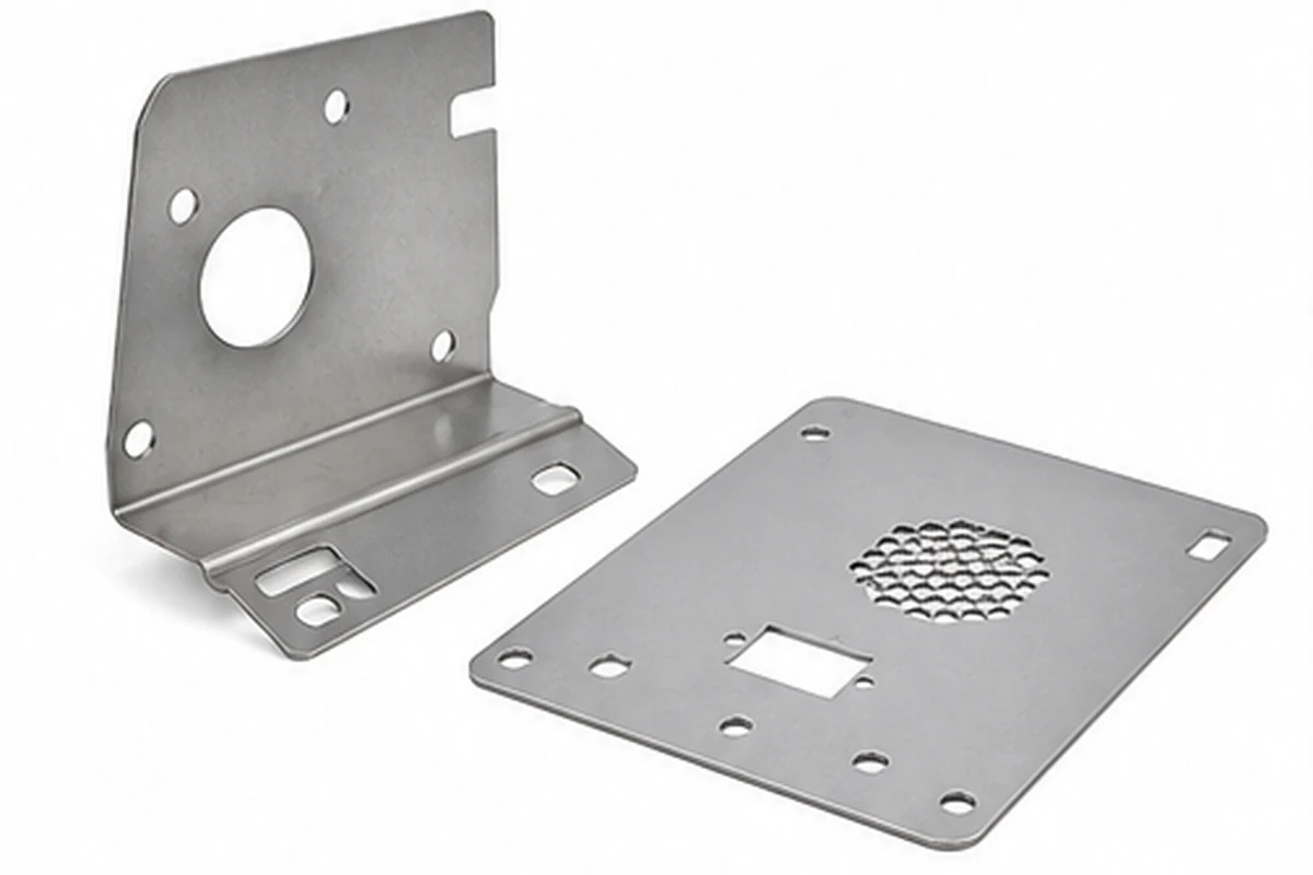
The operator opening should define size, position, corner radii, orientation and mounting-hole relationship. If a vendor template gives dimensions from a centerline, preserve that centerline in the enclosure drawing. Avoid redrawing the template by eye.
Laser cutting can produce accurate openings, but the final condition also depends on deburring, coating and any local forming. Specify which edges are functional, whether the opening is measured before or after coating, and whether bare electrical-contact areas require masking under the buyer’s design.
Control the Shaft and Depth Stack-Up
The critical depth is not simply the cabinet depth. It may include the finished door plane, gasket compression, operator hub, shaft engagement, coupling, bracket position, mounting plate offset and device adjustment range. Put those contributors into a stack-up table.
State the acceptable final range and how it will be checked. A single nominal dimension with no tolerance is not optimism; it is an argument postponed until assembly.
| Stack contributor | Drawing evidence | Buyer decision |
|---|---|---|
| Finished door plane | Door flatness, hinge adjustment and closed position | Approved datum and allowable movement |
| Operator interface | Current manufacturer template and mounting condition | Exact part family and revision |
| Shaft or coupling | Axis, engagement and adjustment envelope | Assembly and final adjustment method |
| Support plane | Bracket or mounting-plate depth from functional datum | Final acceptable depth range |
Keep Door Reinforcement Out of the Mechanism
Large enclosure doors often need return flanges, channels or welded stiffeners. The disconnect operator also needs a keep-out envelope for its body, fasteners, shaft motion and service access. Review both at the same time.
A stiffener that crosses the operator envelope can be trimmed, relocated or locally redesigned, but the change must preserve door rigidity. Removing it after fabrication is less engineering and more expensive sculpture.

Hinges, Latches and Gaskets Change Alignment
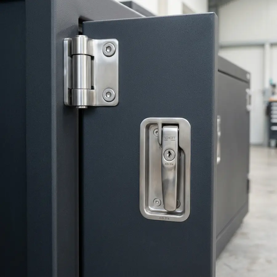
The shaft axis is checked with the door closed, but the door position depends on hinge play, latch pull-in, gasket compression and cabinet squareness. State the inspection condition: fitted hardware, closed latches, defined gasket or approved spacer, and finished coating where required.
Door-mounted hardware should be installed in a sequence that preserves access and protects the finished surface. Our separate electrical enclosure mounting plate DFM guide explains the adjacent mounting-plane and service-access decisions.
Support Brackets Need Stiffness and Access
A buyer-defined switch support bracket or subplate must resist assembly loads without moving the functional axis. Review sheet thickness, return flanges, gussets, fastener access, adjustment slots and weld location. The design should also allow the integrator to install and service the purchased mechanism.
If adjustment is required, define its range and lock-down method. Slots without an inspection target merely provide several convenient positions to be wrong.

Welding and Coating Can Move a Correct CAD Model
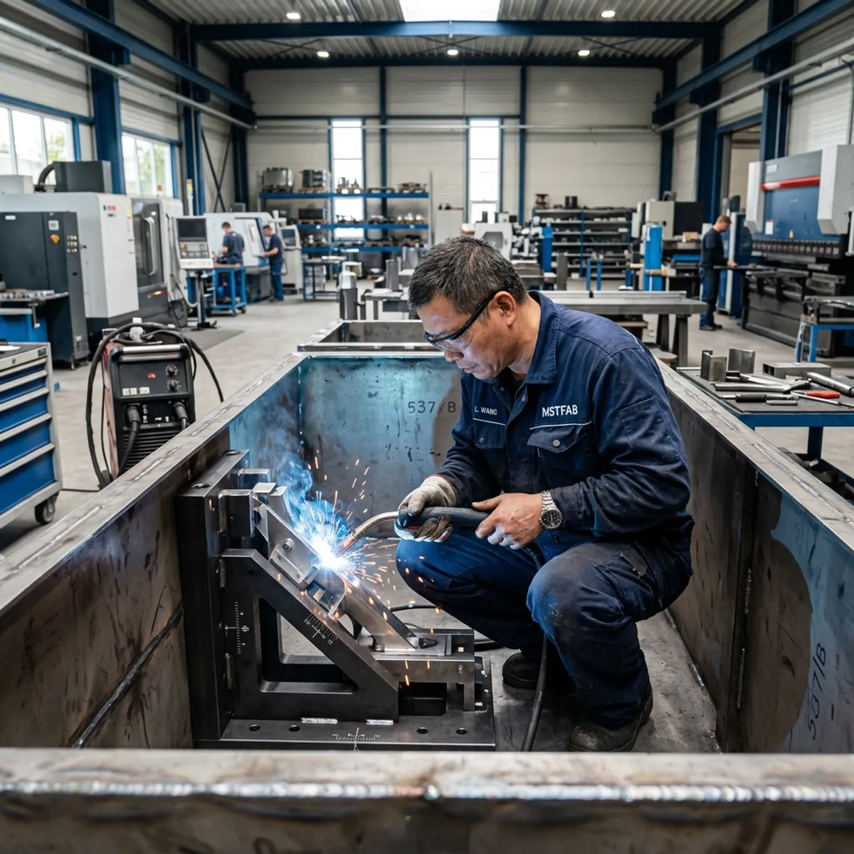
Welding a bracket to a large panel can pull the support plane or twist the door opening. Use fixtures, controlled weld sequence and intermediate checks when the mechanism depends on alignment. Powder coating then adds thickness at cutouts, holes and contact surfaces.
Define whether dimensions apply before or after finish. Masking, threaded features and grounding interfaces remain buyer-controlled requirements. MSTFAB can fabricate and inspect the specified condition; we do not decide the electrical bonding strategy.
Use a Mechanical Dummy for First-Article Inspection
The fabricator does not need to energize a panel to verify buyer-defined mechanical geometry. A controlled dummy, shaft gauge or inspection fixture can check the door cutout, axis, support depth, keep-out and closed-door engagement condition.
The gauge must be tied to the approved component data and revision. Record the setup, datum condition, pass range and measured result. For repeat orders, retain the approved drawing revision, fixture identification and critical inspection points.
Compliance boundary
Mechanical inspection of the shell is not electrical approval of the finished control panel. UL Solutions describes UL 508A as the standard for industrial control panels and maintains current component-use information for panel builders. The OEM, qualified panel builder and certification team must determine the applicable requirements, component acceptance and final tests.
See the official UL 508A component requirements resource for current primary-source context.
Change Control: Small Hardware Change, Large Sheet Metal Consequence
Track the mechanism part number, accessory list, supplier drawing revision, enclosure drawing revision and inspection fixture together. If procurement changes the operator family, engineering should recheck cutout geometry, shaft axis, depth, keep-out and door reinforcement before approving production.
A revision note that says “handle updated” is not enough. State what changed and which interfaces were revalidated. Future buyers will thank you, possibly without realizing why assembly was unusually quiet.
RFQ Checklist
- STEP or STP enclosure assembly
- Controlled 2D drawings and revision
- Exact mechanism and operator part numbers
- Current manufacturer installation template
- Door cutout and mounting-hole pattern
- Functional datums and shaft centerline
- Finished door-to-support depth range
- Adjustment and engagement envelope
- Door stiffener and hardware keep-outs
- Hinge, latch and gasket inspection condition
- Bracket material, thickness and weld notes
- PEM hardware and tool-access requirements
- Powder coating and masking instructions
- Mechanical gauge or dummy definition
- FAI report and repeat-order records
- Prototype and production quantities
Frequently Asked Questions
Can MSTFAB select the disconnect switch and handle?
No. The OEM or electrical designer selects and approves the electrical device and operating mechanism. MSTFAB manufactures the drawing-controlled empty enclosure interfaces.
Can you test the final door interlock function?
We can perform agreed mechanical dimensional checks with buyer-approved gauges or dummies. The panel builder must install, adjust and functionally test the final mechanism and electrical system.
Why provide both the device drawing and the enclosure drawing?
The device drawing defines the purchased mechanism. The enclosure drawing translates that requirement into controlled door, shaft, bracket and mounting-plane features. Both are needed for reliable change control.
Should the operator cutout be measured before or after coating?
The buyer should specify the functional condition. If coating thickness affects fit, define a finished-size requirement or approved masking instruction.
What is the fastest way to reduce first-article risk?
Freeze the exact hardware, provide current manufacturer data, dimension from functional datums and approve a mechanical inspection fixture before production.
Send the Mechanism Data with the Enclosure Drawing
MSTFAB will review the empty sheet metal shell for cutout geometry, shaft alignment, support depth, reinforcement, weld distortion, hardware access and measurable first-article features.
Engineering note: This guide covers build-to-print sheet metal fabrication. It does not replace the OEM’s electrical design review, installation instructions, functional safety assessment or certification process.
 WeChat Contact
 WhatsApp Me Directly