A laser-cut blank that measures flawlessly on a CMM is completely useless if the finished bracket cannot bolt onto your machine frame. It is one of the most frustrating scenes in manufacturing: the laser-cutting shop proudly provides inspection sheets showing +/-0.05 mm contour accuracy on flat sheet metal, yet the second the part is formed on a press brake, mounting holes distort into ovals, return flanges collide with tooling, and the bolt pattern lands 2 mm away from the mating chassis.
Buying laser cutting and CNC bending as disconnected processes turns your procurement team into an unpaid quality mediator. When parts don’t fit, the laser cutter blames the press brake operator’s bend deduction, and the forming shop blames the laser programmer’s flat pattern. Meanwhile, your assembly line is halted, waiting on parts that should have bolted right in.
Quick Answer: A reliable laser-cut and bent sheet metal parts supplier must control the finished 3D formed geometry—not merely the accuracy of the 2D flat blank. For OEM procurement, that means taking single-source ownership of bend deductions, punch radius selection, hole-to-bend clearances, PEM hardware installation, surface finishing, and post-forming inspection.
The decisive purchasing question is simple: Will the finished formed part fit your assembly line without unapproved drilling, filing, or manual bending corrections? MSTFAB manufactures drawing-based custom brackets, U-channels, panels, and chassis components with integrated tooling review and First Article Inspection (FAI) to ensure assembly-ready delivery.
Scope Note: MSTFAB provides drawing-defined laser cutting, CNC press brake bending, hardware insertion, and surface treatment for custom mechanical components and empty enclosures. We manufacture strictly to released customer prints and BOMs. The OEM buyer defines structural loads, mechanical fatigue parameters, and final equipment validation. We do not provide electrical wiring, firmware, or finished machinery.

Why Buy Laser Cutting and Bending Together?
Laser cutting produces the flat blank. CNC sheet metal bending transforms that flat sheet into a load-bearing three-dimensional mechanical component. When these two operations are planned by the same engineering team, the flat pattern is calculated specifically for the exact press brake V-die opening, punch radius, and material elongation characteristics that will be used on the factory floor.
Coordinating cutting and bending under one supplier eliminates the five most common handoff defects:
- Hole Distortion: Round mounting holes placed too close to a bend radius stretch into flared ovals during forming.
- Flange Length Drift: Generic CAD unfold tables miscalculate neutral axis K-factors, leading to short or overgrown return flanges.
- Tooling Interference: Unfolding a deep box or narrow U-channel without checking punch throat depth results in the part colliding with the machine ram.
- Grain Direction Tearing: Bending high-strength aluminum or cold-rolled steel parallel to sheet rolling lines causes micro-cracking along the outside radius.
- Misaligned Fastener Centers: Pre-cut holes for self-clinching PEM hardware shift during forming if bend deductions are not dialed in.
“A perfect flat blank is not necessarily a usable finished part. Your assembly line has the final vote.”

1. Start With the Finished Part Drawing, Not Just Flat DXFs
One of the easiest ways for an RFQ to go off the rails is sending only 2D flat DXF files to a fabricator. A flat DXF communicates 2D cut geometry, but it completely conceals the finished 3D assembly envelope, critical functional datums, bend orientations, and mating hole tolerances.
For an accurate and dependable quotation, provide a complete manufacturing drawing package:
- 3D CAD Model (STEP / STP): Shows the finished geometry, flange relationships, and bend reliefs.
- Controlled 2D PDF: Identifies material alloy and temper, sheet thickness, dimensional tolerances, thread callouts, finish specs, and Critical-to-Quality (CTQ) datums.
- Order Quantity & Release Schedule: Distinguishes prototype verification runs from high-volume repeat orders.
If you already have flat DXF cutting patterns developed for your own internal tooling, let us know during RFQ review. Otherwise, MSTFAB’s engineering team unfolds the 3D model according to our validated tooling library. To understand how cutting data is processed, explore our laser cutting services overview, or review our detailed guide on submitting a laser-cut and bent parts RFQ.
2. Control Hole Positions After Bending (Not on the Flat Blank)
Many OEM brackets and covers are essentially Swiss cheese with precision mounting holes, connector cutouts, and cable slots. Their final positions in 3D space depend directly on bend allowances, punch radii, and forming sequence.
| OEM Component | Critical Inspection Feature | Common Failure Mode If Not Controlled |
|---|---|---|
| Mounting Bracket | Hole-to-bend distance and centerline | Stretched holes prevent mounting bolts from threading cleanly into tapped frames |
| Formed Equipment Panel | Cutout alignment across multiple planes | HMI screens, connectors, or keylocks bind against cutouts |
| U-Channel / Hat Profile | Internal channel width & parallel flanges | Slide-in components or internal subassemblies jam during insertion |
| Formed Machine Cover | Perimeter mounting holes & gap consistency | Uneven cosmetic gaps and oil-canning across large flat faces |
| Chassis Tray Component | PCB standoff positions & card guide datums | Accumulated bend tolerance stack-up misaligns internal electronics |
Smart procurement teams avoid applying blanket ±0.1 mm tolerances to every non-critical dimension, which artificially inflates quoting costs. Instead, specify functional datums where the component mates with other parts in your final assembly. The finished part should be verified against dimensions that actually matter during production assembly.

3. Check Bend Feasibility Before Laser Cutting Begins
The press brake cannot negotiate with an incorrectly designed feature. If a hole is positioned 1 mm from a bend line on 3 mm steel sheet, physics will win every time: the hole will distort. Similarly, if a return flange is 50 mm deep on a 30 mm wide channel, a standard punch die will crash directly into the opposite flange.
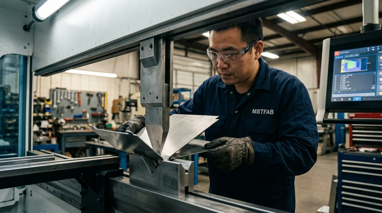
Before launching laser production, MSTFAB performs a rigorous DFM forming review:
- Minimum Flange Length: The return flange must span across the press brake V-die opening (typically
6× to 8× sheet thickness) without slipping down into the die. - Hole-to-Bend Safe Margin: As a rule of thumb, the edge of any cutout or hole should be placed at least
2× material thickness + inside bend radiusaway from the bend line. - Tooling Access & Gooseneck Punches: For deep returns or channel sections, we verify that gooseneck punches or window tooling can form the sequence without mechanical collision.
- Corner Relief Cuts: Ensuring rectangular or teardrop relief notches are placed at corners where two bends intersect, preventing metal tearing and bulging.
4. Material Grade Dictates the Entire Fabrication Route
Specifying simply “steel” or “aluminum” on a quotation request is an invitation for trouble. Every metal alloy, temper, and rolling condition exhibits distinct yield strengths, minimum bend radii, and springback behavior:
- Cold-Rolled Steel (SPCC / DC01 / 1008): Excellent forming ductility and tight bend radius capability. Ideal for indoor enclosures and brackets requiring powder coating.
- Galvanized Steel (SGCC / DX51D): Zinc coating protects against corrosion, but laser cutting burns away zinc along cut edges, and zinc dust buildup in forming dies requires regular tooling cleaning.
- Aluminum 5052-H32: The standard workhorse for formed electronics chassis and equipment covers. Excellent formability with minimal cracking risk.
- Aluminum 6061-T6: Extremely strong and machinable, but prone to cracking if bent over sharp punch radii. Requires larger bend radii (typically
3× to 4× sheet thickness). - Stainless Steel (304 / 316): High tensile strength and work-hardening characteristics. Requires 30% to 50% more bending tonnage and significant springback compensation.
Always name the exact alloy, temper, and thickness tolerance in your RFQ package to prevent unapproved material substitutions.
5. What Does “Assembly-Ready” Actually Mean?
For MSTFAB, assembly-ready means the fabricated sheet metal component is fully prepared for your line operators to install immediately upon opening the crate—without secondary prep work.
CNC Deburring→
Precision Bending→
PEM Fasteners→
Coating / Anodizing→
FAI Inspection→
Custom Foam Packing
Depending on your drawing requirements, an assembly-ready scope includes:
- Tumbled or Edge-Grained Edges: Free of razor-sharp laser burrs and dross, protecting line workers’ hands and cable insulation.
- Installed Threaded Hardware: Self-clinching PEM nuts, studs, and standoffs installed to certified push-out and torque specifications.
- Protected Surface Condition: Clear anodized, zinc plated, or powder coated with designated grounding points masked.
- Verified Critical Interfaces: Formed bolt circles and mounting slots checked on go/no-go gauges.
It does not mean the component is an assembled machine with electrical wiring or software. The OEM integrates the fabricated bracket or cover into their end equipment.
6. Define Hardware and Finishing Before Quotation
OEM equipment components frequently require threaded fasteners for PCB mounting, earth grounds, or enclosure covers. Adding hardware after metal has already been bent is expensive, difficult, and sometimes physically impossible if punch clearances are obstructed.

To avoid scope creep and delayed orders, clarify:
- Hardware Part Numbers: Specify PEM or approved equivalent series, thread sizes (e.g., M3, M4, #6-32, #10-32), and shank lengths.
- Installation Direction: Indicate clearly on the PDF drawing which side the fastener head sits (inside face vs. outside face).
- Surface Finishing & Thread Masking: If parts are powder coated, threads must be masked or chased with a tap to prevent epoxy clogging.
7. Request First-Article Inspection (FAI) Before Volume Runs
A single prototype bracket bent by hand on a toolmaker’s bench proves feasibility, but it does not prove mass-production capability. For new OEM programs, a structured First Article Inspection verifies that the CNC programs, tooling setups, and press brake backgauge stops are repeatable across thousands of parts.

MSTFAB’s FAI protocol verifies the complete manufacturing route:
Flat Blank Laser Dimensions→
Formed Flange Angles (±0.5°)→
Hole-to-Bend Positions (±0.15mm)→
Hardware Push-Out→
Finish Mil Thickness→
Assembly Check
If any adjustment is required during initial prototyping, the CNC brake program is permanently updated in our machine database before series production begins.
8. Compare Suppliers on the Delivered Scope, Not Just Machine Rates
When evaluating bids from multiple sheet metal shops, beware of “cheap” quotes that only price laser cutting machine hours. A quote that excludes deburring, hardware installation, surface finishing, or export crating is not a competitive price—it is an incomplete scope.
| Quotation Scope Item | What OEM Buyers Should Verify | Common Low-Bid Shortcut |
|---|---|---|
| Laser Cutting | Clean nitrogen cut edge, minimal dross, certified material grade | Using shop scrap or oxygen-cutting stainless sheet (causes edge oxidation) |
| CNC Bending | Precision multi-axis backgauges, controlled radii, no die marks | Using incorrect V-dies that cause cracking or severe tool scraping |
| Deburring | Vibratory tumbling or edge-rounding pass | Leaving razor-sharp micro-tabs and burrs for the customer to grind off |
| PEM Hardware | Installed on pneumatic insertion presses with push-out checks | Quoting fasteners as loose bags or using non-standard knockoff hardware |
| Surface Finish | Full coating spec, film thickness, and thread/ground masking | Quoting bare mill finish or skipping critical grounding mask pads |
| Quality Reporting | Dimensional inspection report on approved drawing datums | Zero inspection evidence provided prior to shipment |
| Export Packaging | ISPM-15 wooden crates with customized EPE foam slotting | Throwing formed parts loose into cardboard boxes where flanges bend in transit |
Trust Table: Who Owns What in Laser Cutting & CNC Bending
Clear manufacturing boundaries prevent costly finger-pointing. Here is how responsibility is assigned on an MSTFAB cutting and bending project:
| Fabrication Scope Item | What MSTFAB Controls & Delivers | Deliverable Evidence | Owner |
|---|---|---|---|
| Flat Blank Development | Unfolds 3D CAD to shop tooling; verifies K-factors, bend reliefs, and grain orientation. | DFM review & flat pattern approval | MSTFAB |
| Press Brake Forming | Maintains flange angles (±0.5°) and critical hole-to-bend spacing (±0.15 mm). | First Article Inspection (FAI) dimensional report | MSTFAB |
| Tooling Clearance | Selects punch radius and V-die to avoid die marking and flange collision. | Tooling feasibility sign-off | MSTFAB |
| Hardware Insertion | Installs specified PEM studs and nuts to torque and push-out specifications. | Fastener torque check record | MSTFAB |
| Surface Finishing | Coordinates anodizing, powder coating, or plating with masked ground areas. | Coating thickness & visual sample sign-off | MSTFAB |
| Export Protection | Custom foam-lined cartons and ISPM-15 wooden crates to prevent transit bending. | Packaging photos prior to container sealing | MSTFAB |
| Structural Loads & Design Fit | Fabricates exactly to released print; does not calculate dynamic machine loads. | Certificate of Conformance (CoC) to print | OEM Buyer |
What MSTFAB Manufactures
MSTFAB provides drawing-based laser cutting and precision CNC bending for overseas OEM equipment manufacturers in industrial machinery, electronics, medical devices, automotive, and telecommunications.
Our build-to-print fabrication scope includes:
- Custom mounting brackets, angle brackets, and gusset plates
- Formed U-channels, hat profiles, and stiffener rails
- Equipment front panels, access doors, and connector plates
- Formed machine covers, shrouds, and ventilation hoods
- Chassis trays, base plates, and empty enclosure components
For broader projects involving structural frames or complete subassemblies, explore our comprehensive custom sheet metal fabrication services.
The OEM defines the product geometry and assembly fit. MSTFAB manufactures the approved laser-cut and bent parts.
Frequently Asked Questions
Can one supplier handle both laser cutting and CNC bending for custom parts?
Yes. MSTFAB integrates high-precision fiber laser cutting and multi-axis CNC press brake forming under one production roof. This ensures flat pattern bend deductions, tooling clearances, and hole positions are aligned with the actual press brake dies before metal is cut.
What engineering files are needed for a laser cutting and bending quote?
We recommend sending a 3D CAD model (STEP or STP format) for finished formed geometry along with a controlled 2D PDF drawing detailing dimensional tolerances, material grade, thread callouts, finish specs, and Critical-to-Quality (CTQ) datums.
Can MSTFAB supply bent parts with pre-installed PEM hardware?
Yes. We have dedicated pneumatic insertion presses to install self-clinching PEM nuts, threaded studs, standoffs, and captive screws into laser-cut and bent sheet metal parts prior to shipment.
Does every laser-cut and bent part require welding?
No. Many brackets, U-channels, covers, and chassis trays achieve their full structural rigidity through CNC bending alone without requiring welding. This significantly reduces manufacturing cost and eliminates weld heat distortion.
What is MSTFAB’s typical tolerance for CNC bent sheet metal?
Our standard tolerance is ±0.5° for bend angles, ±0.2 mm for general flange lengths, and ±0.15 mm for critical hole-to-bend dimensions, depending on material grade and sheet thickness.
Request a Laser Cutting and Bending Quote
Need custom laser-cut and CNC-bent components for an OEM program? Send MSTFAB your released drawing package, material requirements, and estimated order quantities.
Our engineering team will review the cutting and bending scope, verify hole-to-bend clearances, and provide a comprehensive line-item quotation within 24–48 hours.
- Email: [email protected]
- Website: https://mstfab.com/
- WhatsApp: +86 173 2831 6456
High-precision laser-cut and bent sheet metal parts built strictly to your drawings. Assembly-ready upon delivery.
 WeChat Contact
 WhatsApp Me Directly