BUILD-TO-PRINT JUNCTION BOX METALWORK
Quick answer: junction box cover fastening DFM defines how a removable sheet metal cover locates, clamps and remains serviceable on an empty enclosure shell. MSTFAB fabricates the body, cover and drawing-defined mechanical interfaces. MSTFAB does not install electrical components, wire the box or certify a finished product.
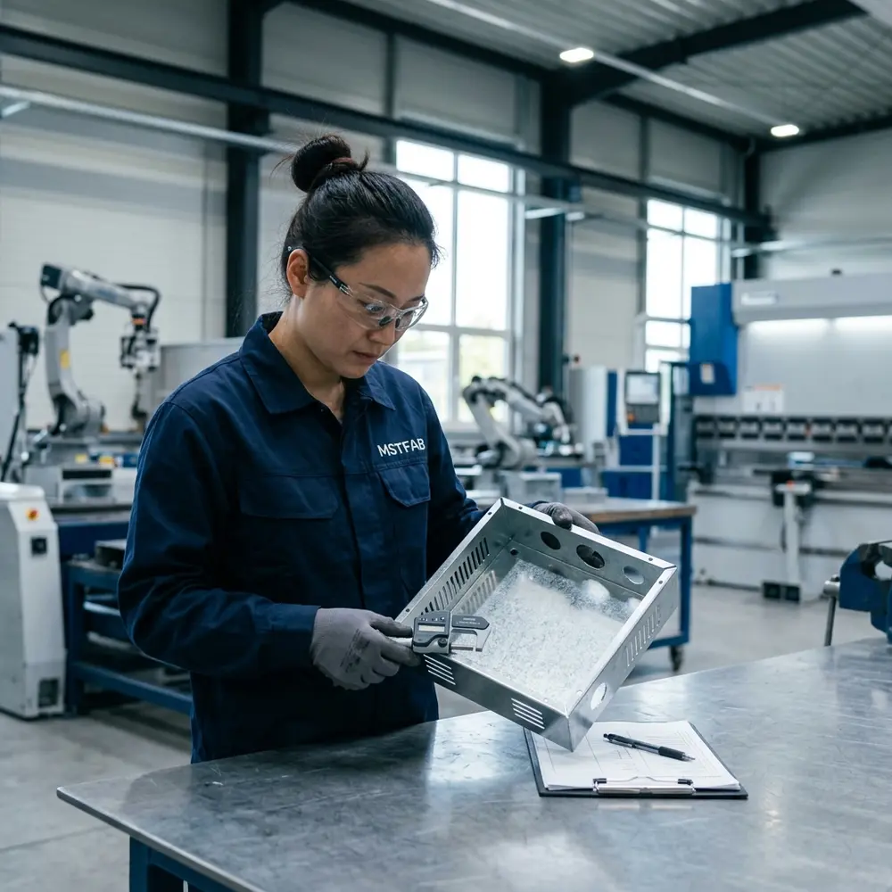
1. Define the product boundary before discussing the screws
A removable cover looks like the least dramatic part of a junction box. Then the first prototype arrives, two screws start cleanly, the third needs persuasion and the fourth has entered witness protection. The usual cause is not one bad hole. It is an undefined interface between the body, cover, hardware, forming process and finished condition.
Empty bodies, removable covers, blank plates, brackets, holes, slots, tabs, welded studs, buyer-specified inserts, coating, mechanical inspection and export packing.
Terminals, cable glands, wiring, electrical assembly, programming, energized testing, commissioning and complete certified junction boxes.
Electrical layout, selected components, gasket design, ingress target, bonding intent, service procedure, final validation and product certification.
This boundary keeps the quotation honest. MSTFAB can manufacture and inspect the metal interface. The buyer or system integrator remains responsible for the complete electrical and environmental performance.
2. Describe the removable-cover use case
Before selecting captive screws or inserts, state how the cover will be used. A commissioning cover opened twice has a different duty from a maintenance cover opened every month. Orientation also matters: a dropped screw is annoying on a workbench and much less charming above a moving conveyor.
Define expected removal cycles and whether tools are permitted.
Wall, ceiling, floor or machine-frame mounting changes handling and dropped-part risk.
State whether the cover must be fully removable, retained or supported during service.
Provide nearby walls, brackets, cable routes and buyer-selected component envelopes.
The customer approves the access concept. MSTFAB reviews whether the approved geometry can be cut, formed, joined, finished and inspected consistently.

3. Locate the cover before asking fasteners to align it
Screws should clamp a cover, not perform a last-minute search for its correct position. Use stable datums, locating tabs, shoulders, formed returns or another buyer-approved feature to establish the cover before tightening begins.
| Drawing input | Why it matters | Useful first-article evidence |
|---|---|---|
| Primary body and cover datums | Prevents each hole from becoming an independent coordinate system | Datum-based dimensional report |
| Hole pattern controlled as a group | Reduces accumulated mismatch after forming and welding | Template, CMM or coordinate check |
| Gap, flushness and corner acceptance | Separates functional fit from subjective cosmetic debate | Approved sample and defined measurement points |
| Clearance-hole and slot intent | Stops adjustment slots from becoming accidental locating features | Sample assembly using specified hardware |
If every edge is held to a heroic tolerance, the drawing does not identify function; it only makes the quotation nervous. Mark the datums, hole group, clamping surfaces and visible gaps that actually affect assembly.

4. Specify captive screws and threaded interfaces as one system
“M4 captive screw” is not enough information for production. The RFQ should identify the approved hardware manufacturer and part number, panel thickness range, hole preparation, head style, installed height, retention method, mating thread and required finish.
- Exact captive-screw or fastener part number
- Exact PEM nut, rivet nut, weld nut or threaded insert
- Base material and finished sheet thickness
- Hole size and preparation before hardware installation
- Distance from bends, corners and welded zones
- Installation direction and tool access
- Thread masking or post-finish thread cleaning
- Retention or torque evidence requested by the buyer
- Permitted substitutions and approval route
- Replacement requirement after repeated service
For deeper hardware selection and installation considerations, use the separate sheet metal threaded inserts guide. This page stays focused on the cover interface instead of borrowing every threaded-hardware keyword on the website.
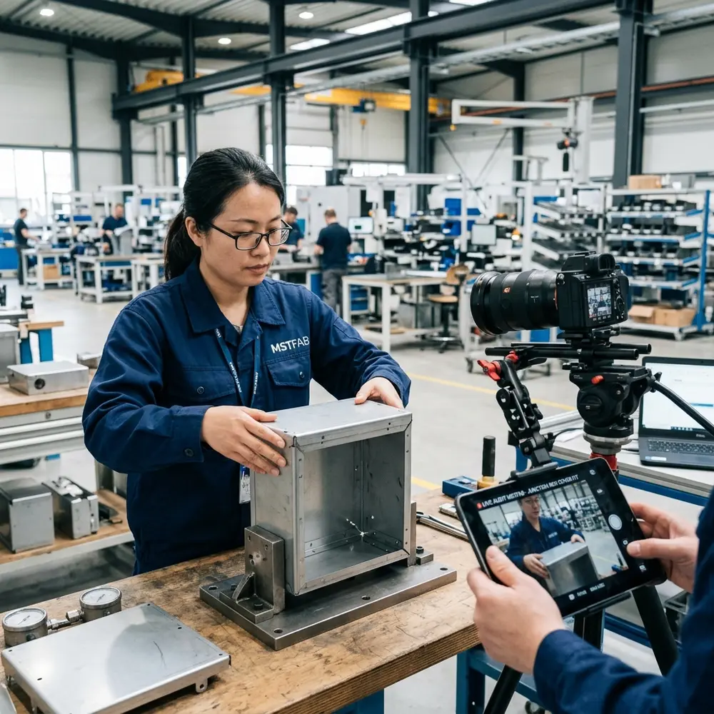
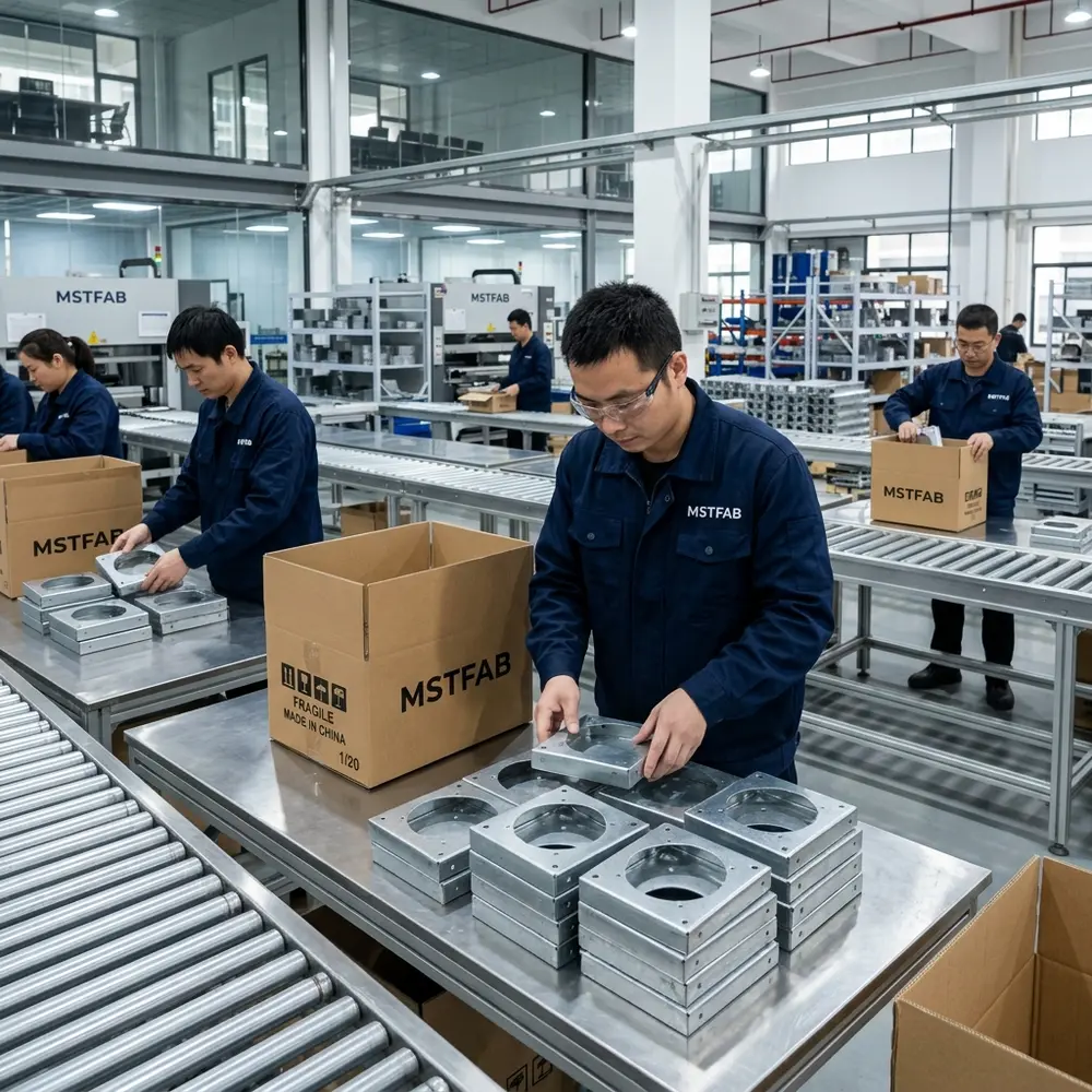
5. Protect the screwdriver and removal path
A screw head can be visible and still be impossible to use. Model the driver bit, handle, approach angle and hand clearance. Also model where the released cover travels after the final fastener is loosened.
Reserve the tool diameter and straight approach length required by the approved fastener.
Allow a technician to support and remove the cover without reaching through a sharp-edge obstacle course.
Check brackets, flanges, rain hoods and machine frames against the service envelope.
Use customer-supplied keep-out envelopes for glands, cables and electrical components.
A red arrow reading “service here” does not create space. CAD remains remarkably literal about that.

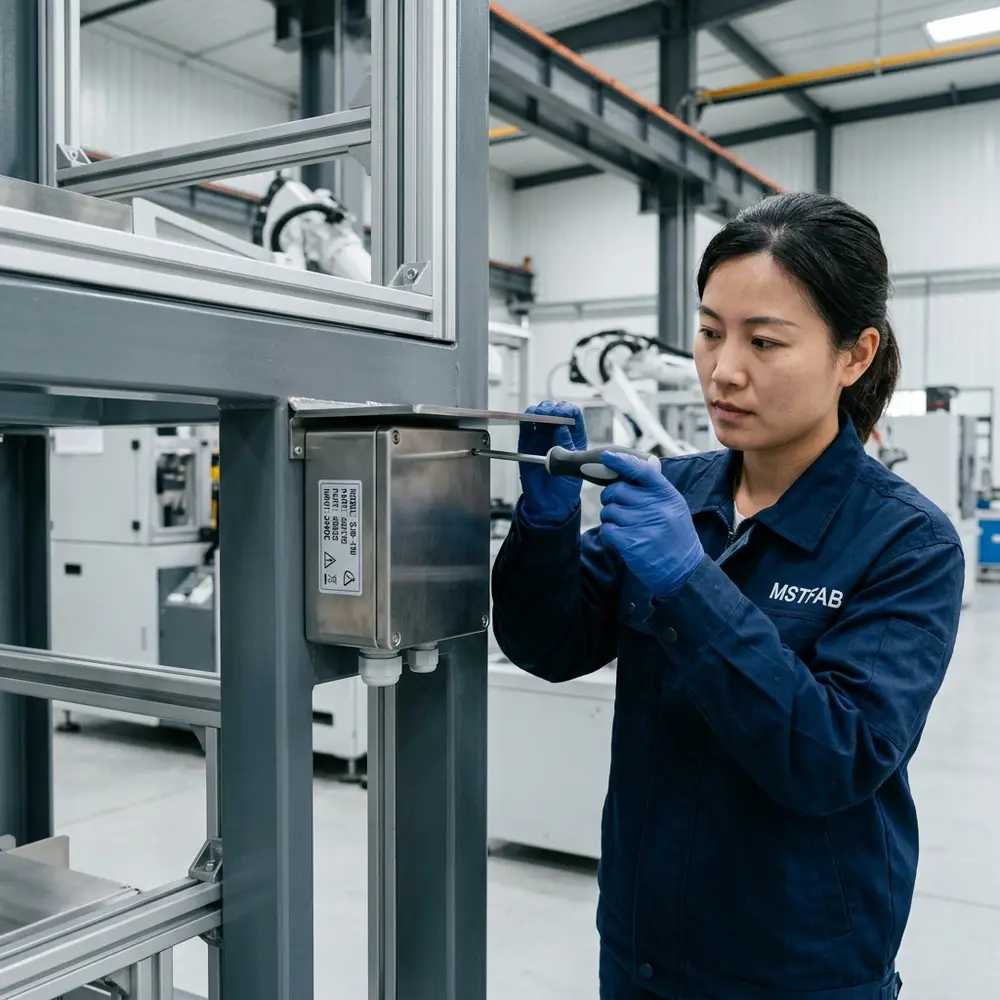
6. Control forming, welding and hardware sequence
The flat pattern may be perfect while the finished opening is not. Bending changes flange relationships, welding can pull corners, grinding can alter edges and hardware may become inaccessible after the final return is formed.
| Process risk | DFM question | Typical control |
|---|---|---|
| Short flange or tight return | Can standard tooling form it without collision? | Tooling review and realistic bend radius |
| Hole close to bend | Will the feature stretch or move during forming? | Distance review or secondary machining |
| Welded body opening | How will heat distortion affect the cover pattern? | Fixture, weld sequence and intermediate measurement |
| Inserted hardware | When is installation access available? | Defined cut-form-hardware-finish sequence |
For repeat orders, record any prototype correction in the controlled model and drawing. A hand-adjusted sample is useful evidence; it is not a revision-control system.
7. Review the finished condition, not only bare metal
Powder coating adds thickness around holes, edges and mating surfaces. It can also fill threads or change how a cover seats. Define masking, thread protection, cosmetic faces and finished gap acceptance before quotation.
If a gasket is involved, the buyer provides the selected gasket, compression target, corner treatment and validation method. MSTFAB can manufacture the metal geometry and inspect drawing-defined dimensions, but material choice alone does not create an IP or NEMA rating.
Grounding and bonding: MSTFAB can create buyer-defined studs, holes and masked contact areas. The buyer owns conductor selection, electrical testing, continuity criteria and certification of the completed assembly.

8. Approve a mechanical first article that answers real questions
The first article should use the intended material, hardware and finish whenever practical. Assemble the body and cover in the specified condition, then check whether it locates freely, every fastener starts without cross-threading and the approved tool can reach each position.
- Body and cover drawing revisions match
- Material and thickness verified
- Functional datums and opening dimensions recorded
- Hole group and insert locations checked
- Cover gap and flushness measured at defined points
- Specified fasteners start and clamp without forcing
- Tool-access envelope confirmed
- Threads and masking checked after finish
- Approved mechanical removal and refit trial completed
- Photos and dimensional evidence linked to the sample
Opening and refitting the cover is a mechanical fit check, not an electrical endurance test. Keeping those responsibilities separate makes the report more useful and the claims more credible.

9. Keep approved covers matched during repeat production
When body and cover variants look similar, use part numbers, revisions, lots or matched-set identification that survives packing. Protect visible faces, threaded hardware and formed edges from metal-to-metal contact.
Any change to material temper, sheet thickness, fastener, insert, coating system, forming tool or weld route should be reviewed against the approved interface. “Equivalent” hardware has a habit of becoming non-equivalent at the exact moment the cover is due on the assembly line.
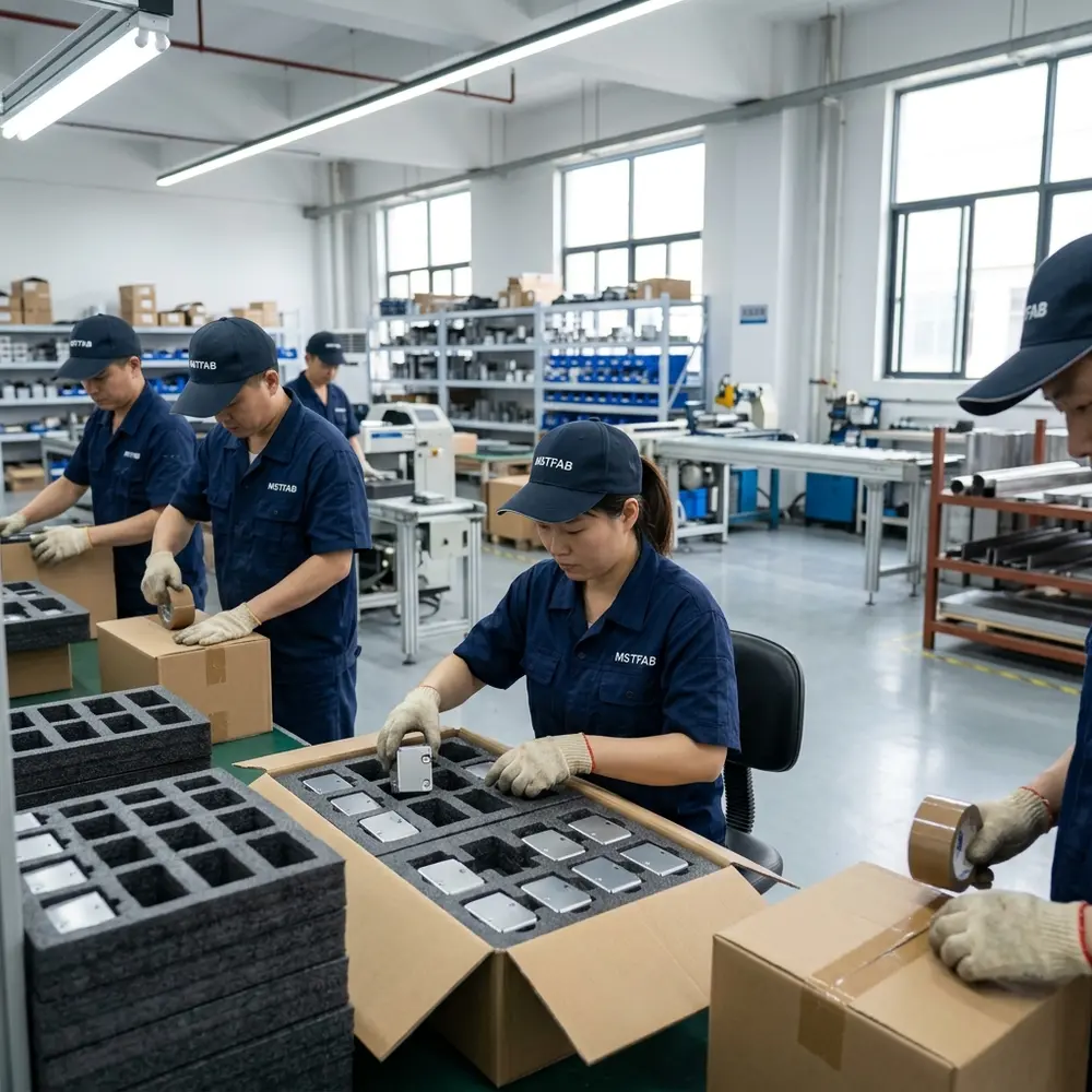
RFQ checklist for an empty shell and removable cover
- STEP or STP model of body and cover
- Controlled 2D drawings with revision
- Material grade and finished thickness
- Cover use case and installed orientation
- Functional datums and critical hole group
- Exact fastener and threaded-interface part numbers
- Tool and hand-access envelopes
- Buyer-defined gasket and bonding interfaces
- Finish, color, texture and masking requirements
- Prototype and repeat-order quantities
- First-article characteristics and evidence
- Packing, identification and delivery destination
Frequently asked questions
Does MSTFAB manufacture a complete electrical junction box?
No. MSTFAB supplies empty sheet metal shells, covers and drawing-defined mechanical parts. The customer installs and validates the electrical system.
Can MSTFAB install captive screws or threaded inserts?
Yes, when the buyer specifies the approved hardware, sheet condition, location, installation requirement and inspection criteria.
Should the screws locate the removable cover?
Usually the interface is more repeatable when dedicated geometry establishes position and the screws provide clamping. The final concept remains subject to buyer approval.
Can MSTFAB claim an IP or NEMA rating for the empty shell?
No. The rating depends on the complete construction, gasket, entries, hardware, assembly and required validation. MSTFAB manufactures drawing-defined metal features only.
What normally causes a cover to fit before coating but bind afterward?
Common causes include coating buildup, unmasked threads, tight edge clearances, distorted openings and acceptance criteria based only on bare metal.
Send the cover interface, not the wiring diagram
Share the empty shell model, cover drawing, hardware, datums, finish, quantities and first-article requirements. MSTFAB will review the cutting, forming, joining, hardware and mechanical inspection route.
 WeChat Contact
 WhatsApp Me Directly