What critical mechanical interfaces must an outdoor telecom cabinet Interface Control Drawing (ICD) define?
An outdoor telecom cabinet Interface Control Drawing (ICD) defines six fundamental boundary interfaces between the empty metal enclosure shell and internal customer payloads: (1) Standard EIA-310-E / ETSI rack rail datums (19-inch or 23-inch horizontal width, 44.45 mm 1U vertical hole spacing, and front-to-rear depth adjustability), (2) Bottom gland plate cable entry matrices (knockouts for power conduits, fiber optics, and grounding leads with IP55/IP65 compression sealing), (3) Thermal heat dissipation zones and airflow corridors (clearance corridors for top heat exchangers or air conditioning supply/return ducts), (4) Door swing kinematics and technician maintenance corridors (minimum 120° door swing clearance with wind latch hold-open stops), (5) Structural concrete foundation anchor bolt patterns and heavy lifting lug datums, and (6) System ground busbar interfaces guaranteeing unpainted electrical continuity (≤ 0.1 Ω bonding resistance).
In telecommunications infrastructure, the metal enclosure shell is the physical boundary that separates sensitive electronic switchgear, rectifier power supplies, and fiber splice trays from harsh outdoor elements. Sourcing empty telecom cabinets requires clear mechanical boundaries. Without a rigorous Interface Control Drawing (ICD), mismatches between cabinet mounting rails, gland plates, and internal sub-racks result in severe field integration delays and costly sheet metal modifications.
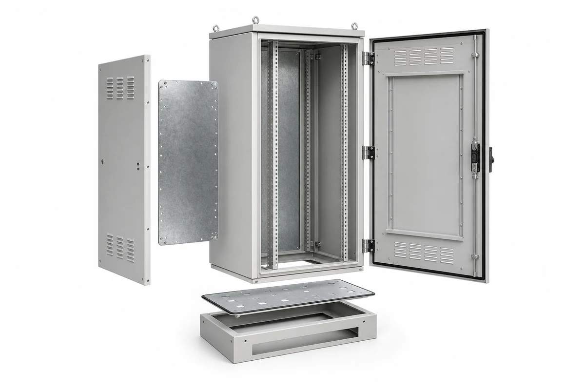
The 6 Critical Boundary Interfaces in Telecom Cabinet ICDs
1. EIA-310-E / ETSI Rack Rail Alignment
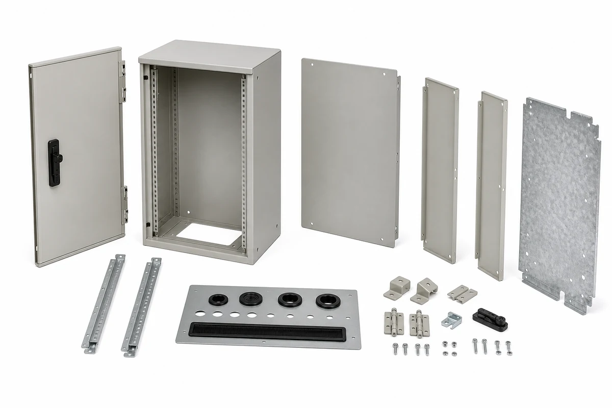
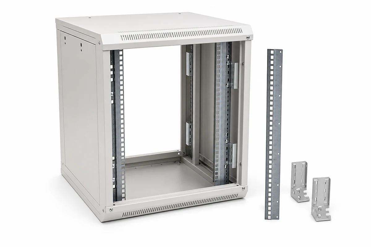
The core internal interface is the vertical equipment rack. ICDs must explicitly call out horizontal hole center-to-center distances: 465.1 mm ±0.5 mm for 19-inch racks or 515.0 mm ±0.5 mm for ETSI racks. Vertical hole pitches must follow the standard 1U repeating pattern (15.875 mm – 15.875 mm – 12.7 mm). Rails must incorporate laser-etched U-markings and provide front-to-back depth adjustment slots ranging from 450 mm to 800 mm.
2. Bottom Cable Gland Plate and Ingress Sealing
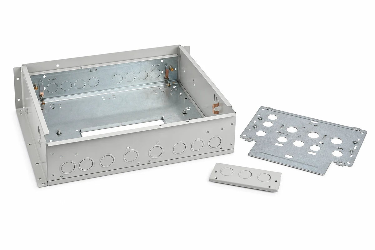
Power feeds, RF coaxial cables, and fiber optic lines enter through the cabinet floor. The ICD specifies a removable 3.0 mm aluminum gland plate equipped with standard PG/metric knockouts (PG16, PG21, PG29, PG36). The gland plate interfaces with a closed-cell EPDM perimeter gasket to maintain IP55 dust and jet-water ingress protection.
3. Service Clearances and Maintenance Corridors
Technicians must service internal power supplies and battery trays in adverse weather conditions. The ICD defines side and rear panel service envelopes: removable side panels for initial cable dressing, minimum 150 mm front clearance for cable bend radii, and unobstructed access to top fan trays.
4. Door Kinematics and Three-Point Compression Latching
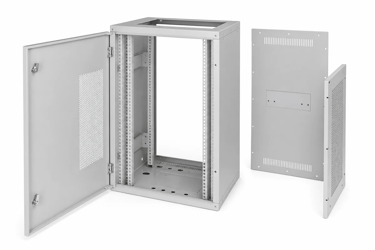
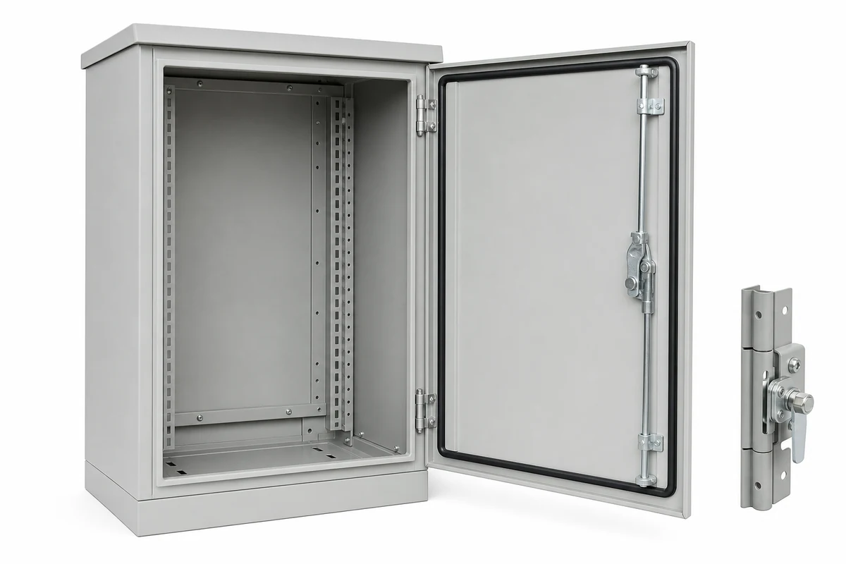
Outdoor cabinet doors must open at least 120° (135° preferred) to clear service walkways. The ICD calls out heavy stainless steel concealed hinges, mechanical wind-stop latches to hold doors open against 50 km/h wind gusts, and multi-point rod-lock compression latches that evenly compress the perimeter hollow-core silicone gasket to 30% nominal height.
5. Structural Frame Datums and Foundation Plinth Mounting
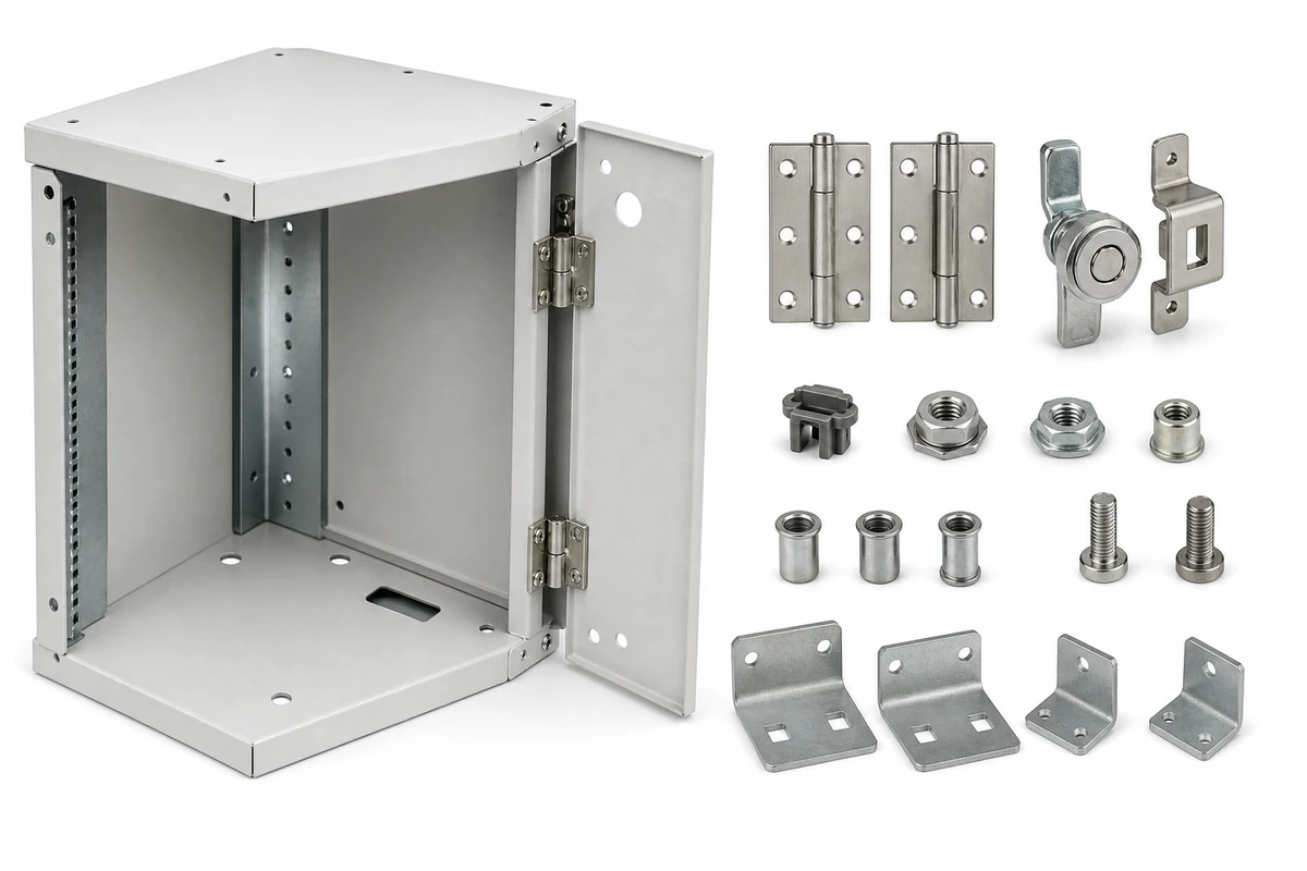
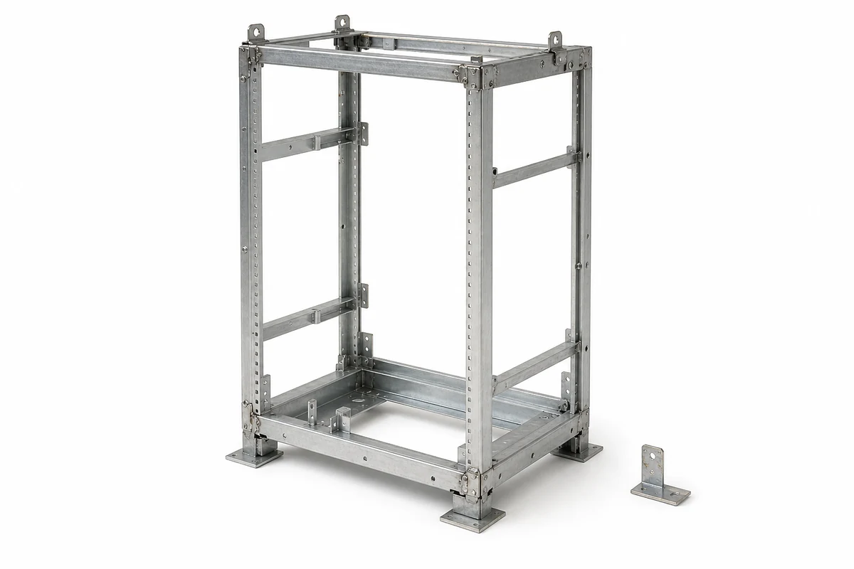
The cabinet base frame interfaces directly with concrete equipment pads or rooftop structural steel. ICDs establish primary datum planes on the bottom plinth, specifying four slotted anchor bolt holes (typically M12 or 1/2-inch studs). Welded tubular steel base frames guarantee diagonal squareness within ±1.0 mm to prevent frame twist under seismic loading.

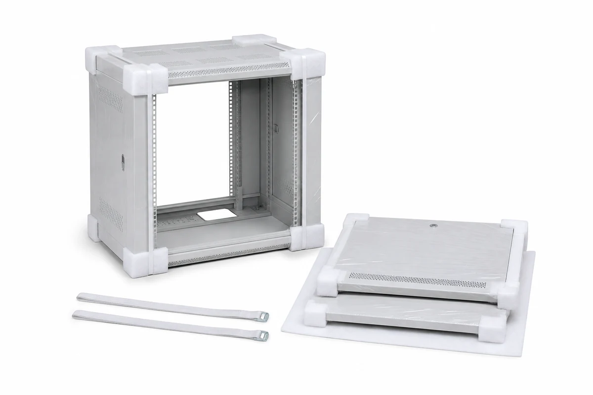
Telecom Cabinet Interface Control Drawing Checklist
Use the engineering checklist below to audit telecom cabinet drawings before releasing tooling and fabrication:
| ICD Interface Section | Governing Standard / Spec | Target Dimension / Limit | Critical Quality Verification Check |
|---|---|---|---|
| 1. 19-Inch Rack Spacing | EIA-310-E / IEC 60297 | 465.1 mm ±0.5 mm center-to-center | Trial fit of master 1U test chassis across full height |
| 2. Gland Plate Knockouts | IEC 62444 / DIN 40430 | PG16/21/29/36 knockouts (±0.1 mm) | Verify knockout bridge tabs break cleanly without tearing |
| 3. Door Swing Kinematics | Telcordia GR-487-CORE | ≥ 120° swing; mechanical stop engaged | Simulated wind load test on open door assembly |
| 4. Gasket Seal Compression | IEC 60529 (IP55/IP65) | 25% – 35% uniform compression | Chalk transfer test along entire door perimeter seal |
| 5. Foundation Bolt Datums | Standard Base Plinth | Diagonal squareness ±1.0 mm | Coordinate measuring machine (CMM) cross-diagonal check |
| 6. Ground Busbar Bonding | UL 508A / Telcordia GR-1089 | ≤ 0.1 Ω electrical bonding | Four-wire Kelvin milliohm bonding continuity measurement |
Partner with MSTFAB for OEM Telecom Cabinets
MSTFAB manufactures outdoor telecom enclosures, battery cabinets, and micro-edge server housings for global telecom providers. Our engineering team reviews ICD boundary interfaces, optimizes sheet metal DFM, and guarantees Telcordia GR-487 and IP55/IP65 environmental compliance. Contact our telecom engineering specialists today.
 WeChat Contact
 WhatsApp Me Directly