⚡ Direct Answer: What Are Standard Sheet Metal Fabrication Tolerances?
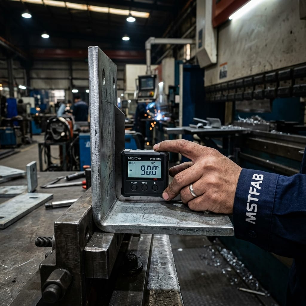
Commercial sheet metal fabrication standard tolerances follow ISO 2768-m (Medium) or ISO 2768-c (Coarse). Precision manufacturing yields the following standard boundaries across sheet thicknesses from 0.8mm to 4.0mm: 1) Fiber Laser Cutting Linear Dimensions: ±0.10 mm (±0.004 in); 2) Laser Cut Hole Diameter: ±0.08 mm (±0.003 in); 3) CNC Press Brake Bending Angles: ±0.5° (precision tooling) to ±1.0° (standard air bending); 4) Bend-to-Bend Linear Distance: ±0.25 mm (±0.010 in); 5) PEM Self-Clinching Hardware Hole Size: +0.08 / -0.00 mm (+0.003 / -0.000 in) to guarantee proper pushout and torque-out resistance; and 6) Welded Chassis True Position Diagonal Squareness: ±0.80 mm (±0.031 in). Tighter tolerances (±0.05 mm) are achievable on CNC machining centers or via precision stamping dies, but require calibrated DFM reviews.
A major driver of inflated sheet metal fabrication costs is “over-tolerancing” — placing machined CNC tolerances (±0.02 mm) onto laser-cut and air-bent sheet metal drawings. Metal sheets exhibit natural material thickness variance (±5% to ±10%), grain direction anisotropy, and springback variations between raw material coils. Understanding realistic manufacturing capabilities ensures flawless assembly without driving manufacturing scrap rates.

Master Sheet Metal Fabrication Tolerance Capability Table
Use this definitive engineering capability table when drafting 2D production drawings (DXF, DWG, PDF) for custom sheet metal parts:
| Fabrication Feature | Commercial Standard | Precision Quality (MSTFAB) | Tight / High-Precision | Tooling / Process Required |
|---|---|---|---|---|
| Flat Laser Cut Length / Width | ±0.20 mm | ±0.10 mm | ±0.05 mm | Fiber laser cutter (constant optical temperature) |
| Cut Hole Diameter | ±0.15 mm | ±0.08 mm | ±0.04 mm | High-speed piercing or CNC reaming |
| Hole-to-Hole Center Distance (Flat) | ±0.15 mm | ±0.08 mm | ±0.05 mm | Single-setup CNC laser cutting |
| Formed Bend Angle | ±1.0° | ±0.5° | ±0.25° | CNC press brake with real-time laser angle tracking |
| Formed Flange Length (Bend to Edge) | ±0.40 mm | ±0.20 mm | ±0.12 mm | Multi-axis backgauge positioning + bottom coining |
| Hole to Bend Line Center Distance | ±0.35 mm | ±0.20 mm | ±0.10 mm | Maintain min 2.5T clearance from bend tangent line |
| PEM Clinch Fastener Mounting Hole | +0.10 / -0.00 mm | +0.08 / -0.00 mm | +0.05 / -0.00 mm | Critical for PEM pushout & torque retention performance |
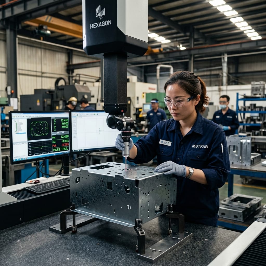
| Welded Enclosure Diagonal Squareness | ±1.50 mm | ±0.80 mm | ±0.40 mm | Precision welding jigs + robotic seam tracking |

Key Factors Influencing Sheet Metal Tolerances
Achieving repeatable precision requires controlling 4 physical manufacturing variables:
- Material Thickness Variation: Standard mill rolling tolerances permit commercial sheets to vary by ±0.05 mm to ±0.12 mm from nominal gauge. In air bending, this thickness variation directly shifts the neutral axis and alters the resulting bend angle by up to ±0.7°.
- Grain Direction Relative to Bend Line: Bending perpendicular to the sheet rolling grain direction delivers maximum ductility and minimal springback. Bending parallel to the grain increases cracking risk and widens angle variance.
- Hole Proximity to Bend Radii: Holes punched or cut closer than 2.5× material thickness (2.5T) to the bend tangent line will stretch into teardrops during forming. If tight hole true position is mandatory, cut relief slots or ream holes secondary to forming.
- Thermal Distortion in Welding: Extensive TIG/MIG seam welding introduces heat accumulation that warps thin sheet metal chassis. Welded assemblies require symmetrical stitch welding, rigid clamping jigs, or cold-joining alternatives (self-pierce riveting or tox clinching).

Streamline Your Precision Sheet Metal Fabrication Procurement & Production
MSTFAB provides end-to-end custom precision sheet metal fabrication, full material traceability (EN 10204 3.1 MTRs, XRF PMI), and flexible supply chain agreements (Blanket POs, VMI, Frameworks). Request a DFM review and instant quote within 24 hours.
Frequently Asked Questions (FAQ)
What happens if a PEM hardware mounting hole is laser cut 0.1mm too large?
PEM self-clinching nuts and standoffs rely on cold-flow displacement of sheet metal into the undercut groove of the fastener shank. If the mounting hole is oversized by even +0.10 mm, insufficient host metal flows into the shank, resulting in a 50% to 80% loss in pushout strength and torque-out resistance, causing the fastener to spin or pop out during final field assembly.
How does powder coating affect finished sheet metal tolerances?
Powder coating adds 60 to 120 microns (0.06 to 0.12 mm) of dry film thickness per coated surface. On a tight slot or slip-fit hole, this reduces clearance by 0.12 to 0.24 mm. Critical holes, grounding studs, and precision slide tabs must either be masked during coating or dimensioned on CAD models with pre-paint clearance allowances.
What standard general tolerance block should buyers specify on sheet metal drawings?
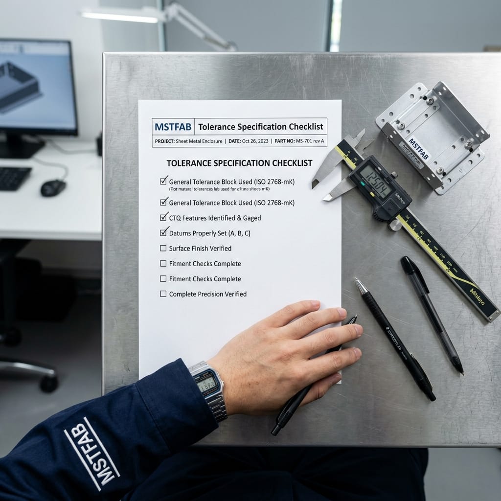
We recommend citing ISO 2768-mK (General tolerances for linear and angular dimensions: Medium; Geometrical tolerances: Class K). This provides clear baseline rules for non-critical features while allowing engineering teams to explicitly highlight Critical-to-Quality (CTQ) dimensions with tighter custom callouts.
 WeChat Contact
 WhatsApp Me Directly