⚡ Direct Answer: How Does a Manufacturer Produce Sheet Metal Parts from CAD Drawings?
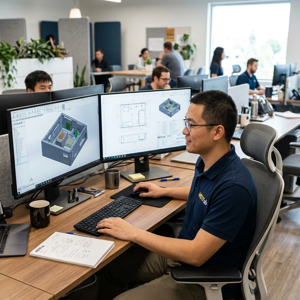
A professional sheet metal parts manufacturer from CAD drawings utilizes a digital CAM workflow to translate client 3D STEP/IGES models and 2D dimensioned PDF prints into physical metal assemblies without manual conversion errors. The workflow encompasses automated 3D CAD unfolding with material-specific K-factors, high-efficiency laser nesting, CNC press brake offline simulation to prevent tool crashes, robotic joining, and first article inspection (FAI) against the original digital engineering model.
Digital CAD-to-Metal Manufacturing Workflow
| CAD Workflow Phase | Software / Machine Tool | Deliverable & Quality Check |
|---|---|---|
| 1. CAD Import & DFM Audit | SolidWorks / Inventor 3D CAD | Verifies bend radii match brake tooling; identifies hole-to-bend distortions. |
| 2. Unfolding & Nesting | CAM Nesting Engine with dynamic K-factors | Calculates flat blank dimensions; optimizes raw sheet utilization >85%. |
| 3. Laser Blanking & Bending | 15kW Fiber Laser + 7-Axis CNC Press Brake | Direct CNC file execution eliminating manual machine data entry errors. |
| 4. CMM Inspection Comparison | Optical Coordinate Measuring Machine (CMM) | Direct CAD overlay color mapping showing dimensional deviation down to ±0.02 mmmm. |
Manufacture Directly from Your CAD Models
Upload your 3D STEP and 2D PDF drawing files to MSTFAB. Receive a comprehensive DFM manufacturability review and itemized quote within 24 hours.
Frequently Asked Questions on CAD Manufacturing
What happens if there is a discrepancy between the 3D STEP model and 2D PDF drawing?
In industrial contract manufacturing, the 2D PDF print represents the legally binding quality specification for tolerances, threads, and hardware callouts. Whenever our CAM software detects a geometric mismatch between the 3D STEP and 2D PDF, our engineering team flags the variance on a formal DFM inquiry sheet for client clarification before cutting metal.
 WeChat Contact
 WhatsApp Me Directly