How do fabricators accurately interpret and execute sheet metal fabrication based on 2D engineering drawings?
Executing sheet metal fabrication from engineering drawings requires a strict hierarchy of authority: the 2D PDF drawing serves as the legal contractual standard for tolerances, material specifications, and surface finishes, while the 3D STEP model provides nominal spatial geometry. Precision manufacturing demands verifying: (1) title block revision letters and general tolerance blocks (ISO 2768-m or ASME Y14.5), (2) explicit inside bend radius callouts matching press brake tooling libraries, (3) standardized AWS A2.4 weld symbols and grain direction arrows, (4) self-clinching hardware part numbers and masking notes, and (5) comprehensive First Article Inspection (FAI) reports documenting critical-to-quality (CTQ) dimensions.
1. The Blueprint Standard: Why 2D Drawings Remain Indispensable
In an era dominated by 3D CAD modeling, some designers assume that sending a STEP file is sufficient for production. However, in professional OEM sheet metal manufacturing, a 3D model represents only nominal geometric shapes. It lacks legal contractual authority regarding critical engineering boundaries:
A STEP file cannot tell the press brake operator whether a flange tolerance is ±0.1 mm or ±0.5 mm; it cannot indicate whether internal weld nuts must be masked before powder coating; it cannot define surface roughness (Ra) standards on brushed stainless steel; and it cannot convey critical GD&T functional datums. The 2D engineering drawing (PDF) remains the definitive legal contract between the buyer and the fabricator.

2. The Hierarchy of Authority: 2D Drawing vs. 3D Model Conflicts
When discrepancies arise between a 2D drawing and a 3D CAD model, manufacturing halts until the customer clarifies design intent. To avoid costly delays, MSTFAB contracts enforce a clear standard hierarchy of authority:
- 2D PDF Drawing: Governs material alloy and temper, critical tolerances, GD&T feature control frames, surface treatments, thread specifications, and inspection criteria.
- 3D STEP / Solid Model: Governs complex contoured surfaces, spatial bend sequencing, and flat pattern unfolding using shop-calibrated K-factors.
- Purchase Order Notes: Governs packaging, shipping, delivery schedule, and quality certification documentation (e.g., mill test certificates, FAI reports).

3. Anatomy of a Production-Ready Sheet Metal Drawing
A flawless engineering drawing must communicate complete technical intent without ambiguity:

- Title Block & Revision Control: The revision letter (e.g., Rev C) must match the purchase order and 3D CAD model file naming. Drawings must declare the projection angle (Third Angle Projection for North America; First Angle Projection for Europe/ISO).
- Material Callout: State the exact alloy and temper—never write generic terms like “Aluminum” or “Steel”. Specify “ALUMINUM 5052-H32 PER ASTM B209, THICKNESS 2.0 mm ± 0.08 mm”.
- Inside Bend Radius: Specify a uniform inside bend radius across all bends (e.g., IR = 2.0 mm TYP). Avoid declaring zero inside radius, which is physically impossible to form.
- Grain Direction Arrows: For cosmetic parts (brushed stainless steel or aluminum), include double-ended arrows indicating grain direction relative to primary bend lines.
- Welding Callouts: Use standard AWS A2.4 weld symbols detailing process, fillet size, intermittent pitch, and finish contour (e.g., grind flush).

4. First-Piece Inspection & CNC Bending Verification
Before releasing a batch of sheet metal parts, the first formed piece undergoes rigorous first-article inspection (FAI) at the press brake. The operator verifies bend angles using calibrated digital protractors and measures flange heights using digital height gauges on granite datum blocks.

5. Fixturing & Assembly Fit Verification
Welded chassis and enclosures must maintain tight assembly alignments specified on the engineering drawing. Components are clamped into precision fixtures that enforce dimensional squareness and mounting hole true positions before welding.


6. Quality Inspection & AS9102 First Article Inspection (FAI)
To guarantee complete compliance with customer engineering drawings, MSTFAB quality control executes formal First Article Inspection reports (FAIR):
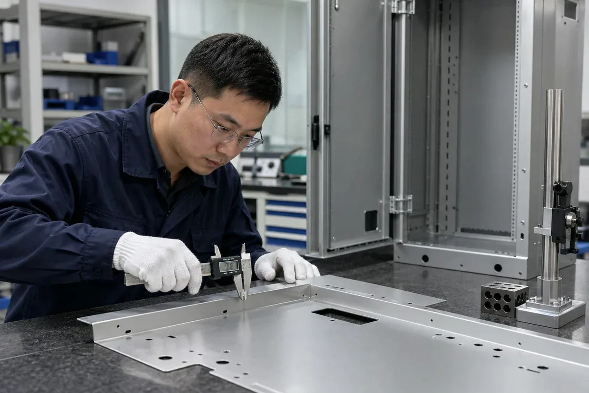
Every dimension on the drawing is assigned a unique balloon number. The quality inspector measures each ballooned characteristic on the physical part and records the nominal value, drawing tolerance, and actual measured result on the FAI report.

7. Engineering Drawing Quality Standard Matrix
MSTFAB manufactures precision sheet metal compliant with international drafting and tolerance standards:
| Drawing Feature | Governing Drafting Standard | Standard Fabrication Tolerance | Verification Method |
|---|---|---|---|
| Laser Cut Hole Pitch | ASME Y14.5 / ISO 2768-m | ±0.05 mm | Optical vision system / Calibrated pin gauges |
| Formed Flange Linear Dimensions | ISO 2768-m (Medium) | ±0.25 mm (up to 500 mm length) | Digital height gauge on granite surface plate |
| Formed Bend Angles | ISO 2768-f (Fine) | ±0.3° to ±0.5° | Precision digital bevel protractor |
| Weld Joint Compliance | AWS D1.1 / AWS D1.3 / AWS D1.6 | 100% visual inspection; zero cracks | Fillet weld gauge; dye penetrant test (PT) |
| Powder Coat Film Thickness | ISO 2808 / ASTM D1186 | 70 μm – 100 μm DFT | Electromagnetic digital dry film gauge |
| Thread Acceptance | ANSI/ASME B1.1 / ISO 965 | Class 2B (Unified) / 6H (Metric) | Calibrated GO / NO-GO thread plug gauges |
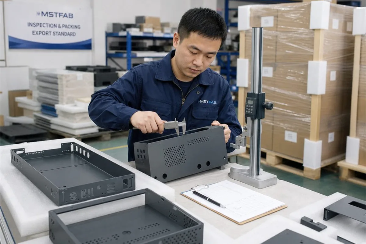
Submit Your 2D Engineering Drawings for Precision Fabrication
MSTFAB manufactures custom sheet metal parts built strictly to your 2D blueprints. Benefit from expert DFM review, full AS9102 First Article Inspection reports, and certified ISO 9001 quality management.
 WeChat Contact
 WhatsApp Me Directly