⚡ Direct Answer: What Drives Sheet Metal Batch-to-Batch Consistency?
Sheet metal batch-to-batch consistency is determined by controlling four primary sources of physical variation across successive production runs: 1) Raw material mill tolerance and grain orientation (yield strength shifts of ±10% cause 0.5° to 1.5° angular springback variations in air bending); 2) CNC machine program and tooling calibration freeze (locking dedicated punch/die sets and laser focal heights rather than substituting interchangeable press brake tooling); 3) In-process Statistical Process Control (SPC) enforcing Cpk ≥ 1.33 on Critical-to-Quality (CTQ) mounting hole positions and overall envelope dimensions; and 4) Dedicated inspection check fixtures that verify hole alignment and chassis squareness under production clamping conditions. Without standardized raw material certifications and locked CNC setups, repeatability inevitably degrades across reorders.
When sourcing custom sheet metal enclosures, brackets, and structural subassemblies, OEM buyers frequently encounter a frustrating phenomenon: Batch 1 fits perfectly during initial prototype testing, but Batch 3 or Batch 5 causes assembly line stoppages because mounting holes miss their mating bosses by 0.6mm or door latches bind. Sheet metal is inherently subject to elastic springback, internal rolling stresses, and sheet thickness variances. To guarantee high repeatability over multi-year production programs, manufacturers must transition from subjective manual adjustments to rigorous statistical process control.

Key Metrics OEM Buyers Should Measure for Batch Consistency
To separate world-class precision fabricators from low-tier job shops, buyers must establish contractual quality agreements centered on measurable metrological indicators rather than vague commercial promises.
| Process Domain | Physical Variation Driver | Standard Shop Tolerance | MSTFAB Precision Target | SPC & Metrology Verification Method |
|---|---|---|---|---|
| Raw Material Inflow | Coil thickness variation (±0.12mm) & grain orientation shifts | Commercial ASTM A1008 tolerance | Restricted gauge tolerance (±0.04mm), grain-aligned nesting | Mill Test Certificate (MTR) review + 5-point ultrasonic micrometer check |
| CNC Laser Profile Cutting | Thermal beam drift, nozzle wear, slat table vibration | ±0.25 mm | ±0.05 mm | High-resolution optical 2D vision scanner (100% first-sheet verification) |
| CNC Press Brake Forming | Yield strength springback, V-die wear, backgauge drift | ±1.0° angle / ±0.40 mm flange | ±0.3° angle / ±0.15 mm flange | Real-time laser angle measurement & adaptive crowning; X-bar & R control charts |
| Weldment Assemblies | Thermal distortion, localized weld shrinkage, clamp wear | ±1.5 mm diagonal squareness | ±0.35 mm diagonal squareness | Hardened datum pin welding fixtures + articulated FaroArm 3D coordinate scanning |
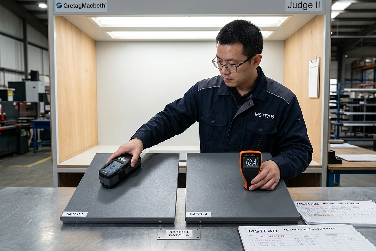
| Powder Coating & Plating | Powder lot chemistry, bake oven thermal curves, spray density | ±40 μm thickness, visible color drift | 60–80 μm strictly maintained; ΔE < 0.8 | Magnetic DFT gauge (ASTM D7091) + BYK Gardner spectrophotometer & gloss meter |
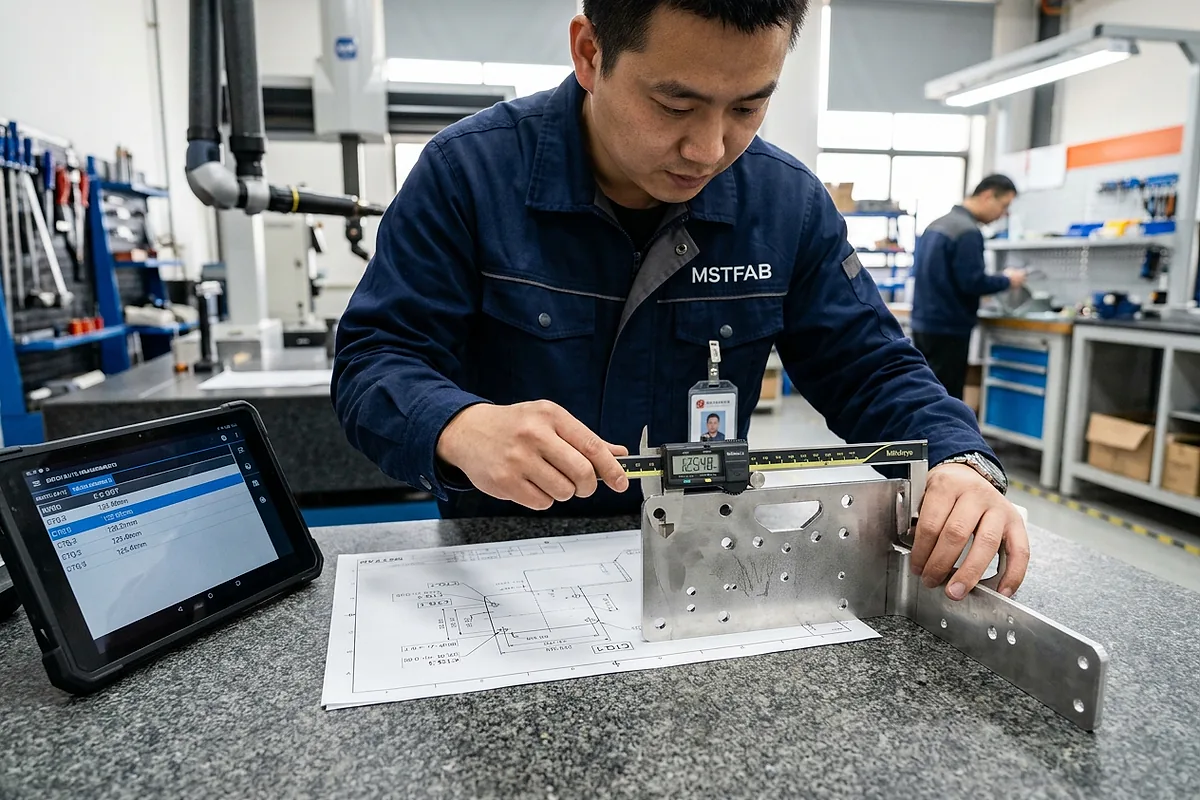
Statistical Process Control (SPC) for Recurring Production Lots
A reliable batch-to-batch guarantee cannot rely on inspecting parts after they are completed; it requires continuous statistical feedback during manufacturing. At MSTFAB, we track CTQ dimensions using Shewhart X-bar and R control charts to calculate process capability indices:
- Cp (Process Potential): Measures the spread of the process relative to the specification limits without regard to centering. A minimum Cp ≥ 1.50 is enforced during initial pilot runs.
- Cpk (Process Capability): Measures both spread and centering against drawing limits. We require Cpk ≥ 1.33 (<66 defects per million opportunities) for general commercial parts and Cpk ≥ 1.67 for aerospace and mission-critical telecom enclosures.
- Western Electric Rules: Automatic tool shut-off triggers if 4 out of 5 consecutive points fall beyond 1 standard deviation on the same side of the mean, detecting thermal backgauge drift before out-of-spec parts are formed.
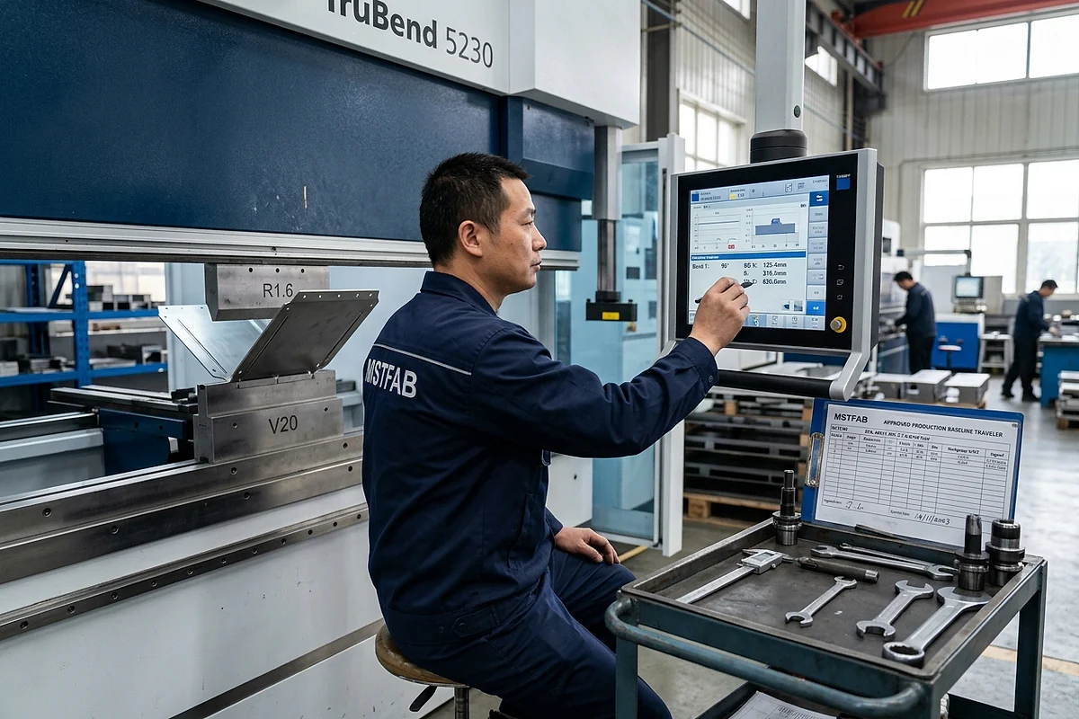
Physical Root Causes of Batch Drift & Countermeasures
Understanding why sheet metal dimensions drift between batches is essential for effective supplier management:
- Grain Orientation in Flat Nesting: Bending parallel to the rolling grain direction requires less tonnage but results in higher cracking risk and inconsistent bend radii compared to bending perpendicular (transverse) to the grain. MSTFAB locks grain orientation directly into the CAM nesting files so nesting algorithms never rotate parts randomly to maximize material yield.
- Tooling Wear & Substitution: Budget suppliers frequently use whatever punch and V-die happens to be mounted on the press brake. Even a 0.2mm difference in die shoulder radius alters the neutral axis (K-factor), shifting formed leg lengths by 0.3mm to 0.5mm. MSTFAB assigns dedicated, serialized tooling IDs in the Manufacturing Routing Traveler.
- Weldment Heat Input & Fixture Wear: Repeated thermal cycles cause manual welding jigs to expand or lose clamping concentricity. MSTFAB utilizes CNC-machined, hardened fixture plates with replaceable locating pins, verifying fixture alignment against master CAD models every 500 cycles.


Achieve Flawless Batch-to-Batch Repeatability Consistency With MSTFAB
MSTFAB enforces ISO 9001 certified quality gates, CMM automated metrology, locked CNC bend sequences, and tamper-proof golden sample governance. Guarantee batch-to-batch repeatability from pilot run to mass production.
Frequently Asked Questions (FAQ)
How does raw material thickness variance affect press brake bend angles?
In air bending, the punch does not bottom out into the die; the angle is determined strictly by punch penetration depth. A sheet thickness variation of ±0.10mm changes where the punch contacts the sheet, translating to an angular error of 0.8° to 1.5°. MSTFAB utilizes press brakes equipped with dynamic optical angle sensors that measure the flange angle during bending and adjust ram depth automatically in real time.
What sample size is required to validate batch repeatability under ISO 9001?
For standard production runs, ANSI/ASQ Z1.4 (ISO 2859-1) General Inspection Level II Normal Sampling with an Acceptance Quality Limit (AQL) of 1.0 or 0.65 is industry standard. For critical aerospace or medical brackets, MSTFAB conducts 100% inspection on CTQs or uses a 30-piece initial subgroup to calculate formal Ppk/Cpk capability.
Can powder coat thickness cause mounting hole assembly failures between batches?
Yes. Standard electrostatic powder coating adds 60 μm to 100 μm (0.06mm to 0.10mm) per side, reducing through-hole diameters by up to 0.20mm. Inconsistent powder build-up across batches can prevent tight-tolerance fasteners or captive nuts from engaging. MSTFAB engineers high-temperature silicone masking plugs and caps into the production routing to protect CTQ holes and ground studs.
 WeChat Contact
 WhatsApp Me Directly