A fan carrier can have the right outside dimensions and still catch on a screw head halfway into the chassis. The useful RFQ defines the finished insertion path, not just the tray outline.
Quick answer: Custom network switch fan tray metal carriers are drawing-defined mechanical components that support, locate and retain OEM-selected fan assemblies. The metalwork may include a formed tray, fan mounting plate, guide flanges, retaining brackets and specified mechanical hardware.
The carrier is not a complete operating fan module. The equipment OEM defines the fan and chassis interfaces and remains responsible for fans, connectors, electronics, airflow, thermal performance, hot-swap operation and final equipment validation.
Buy the Carrier, Not an Undefined Fan Module
The same phrase, “fan tray,” can mean an empty metal part or a populated, tested assembly. Those are different purchases.
List what the supplier must deliver: a base carrier, front or rear mounting plate, guide features, brackets, covers and any agreed hardware. Fans shown in a reference assembly do not automatically become supplied items. Neither do handles, captive screws or latches.
This guide concerns metal components inside network equipment. Full rack structures, cabinet doors and rail layouts belong to the broader network cabinet fabrication scope. A rack cabinet drawing cannot define the internal carrier for a particular switch.
What the Router References Actually Establish
Juniper Networks’ PTX10004 chassis documentation identifies fan trays and their controllers as separate components within a router chassis. Cisco’s ASR 914 installation guide describes a modular fan tray, its chassis seating and captive retention screws, with equipment-specific replacement cautions.
Both examples are routers, not evidence of a universal network switch layout. They establish the use of removable fan assemblies in network equipment, not the dimensions, material or thermal performance of a new carrier.
MSTFAB is not presented as a supplier to either brand. No proprietary accessory drawings or replacement procedures are reproduced here. Use the current manufacturer documentation for the actual equipment and the OEM’s own released design.
Choose the Correct Mechanical Purchasing Unit
The OEM chooses the product architecture. A fabrication review should not turn a fixed fan bracket into a removable module, change the fan model or introduce live-replacement claims.
For a removable design, provide the complete relevant mechanical assembly, not just the loose tray. Identify reference-only fans, chassis parts and connector envelopes so the fabricator can review geometry without quoting those purchased components.
Release the Fan Mounting Interface
An approximate fan size is not a manufacturing drawing. Supply the approved fan model and its controlled mechanical interface, or a drawing that fully defines the mating requirements.
- Mounting pattern: hole sizes, positions, datums and the specified fastening arrangement.
- Opening geometry: the approved profile and any guard or clearance requirement.
- Orientation: identify how the fan is located; do not infer airflow from the appearance of the metalwork.
- Surrounding space: include the relevant connector, cable and adjacent-part envelopes without assigning electrical design to the fabricator.
- Supply responsibility: distinguish reference components, customer-furnished items and supplier-installed mechanical hardware.
The OEM must approve a change of fan model or orientation even when the new part appears to fit the same opening. Similar outside dimensions do not establish electrical or cooling equivalence.
Control the Finished Insertion Envelope
A carrier that fits before finishing may bind afterward. The drawing should identify whether critical dimensions apply before or after the specified treatment and which surfaces establish the sliding relationship.
- Width and guide relationship: define the relevant mating limits, formed surfaces and datum scheme.
- Return flanges: check their full path through the opening, including the entry and final seated position.
- Protrusions: include screw heads, studs, inserts and other installed hardware in the envelope.
- Finishing: identify coating requirements and any approved masking on functional surfaces.
- Handling: protect thin guides and long formed sections from distortion before assembly.
Useful drawing question: is the quoted critical width a bare-metal dimension, a finished outside envelope or the available chassis opening? Record the answer before cutting.
The OEM must approve the clearance scheme and acceptance limits. This article does not prescribe a universal sliding clearance, coating allowance or manufacturing tolerance.
A dimension on the flat blank cannot confirm the finished relationship between two bent guide walls. Measure the characteristics that actually control installation.
Review Guide Flanges in the Formed Condition
CNC bending can produce many carrier walls, channels and guide flanges, subject to the actual material and geometry. Feasibility depends on more than the number of bend lines.
- Material grade, condition, thickness and the approved bend radius.
- Finished flange height, parallelism and angular relationships where controlled.
- Hole-to-bend distances and the risk of distortion near formed features.
- Tool access, return flanges, bend sequence and reliefs.
- Any joining method, reinforcement and the inspection stage after joining.
Some carriers need only cutting and forming; others use multiple joined parts. Welding is not a default requirement, and adding a weld can change both distortion risk and the finish route.
See MSTFAB’s CNC sheet metal bending services for the broader process. Proposed changes to a functional guide, opening or fastening arrangement still require OEM approval.
Specify Retention Before Quoting Hardware
Define what stops the carrier in its installed position, what retains it and how the approved removal method works. Reaching the back of the opening is not the same as reaching the correct mechanical stop.
- Identify exact captive screws, handles, latches, inserts or studs by the approved BOM.
- Show their mounting positions, installation direction and relevant protrusions.
- Define tool and handling access in the surrounding assembly.
- State which hardware is supplied loose, installed by the fabricator or fitted by the OEM.
- Agree the assembly sequence around finishing and any required hardware checks.
A photo of a handle is not a hardware specification. If a particular retention component is essential, confirm its identity and availability before comparing prices.
Material, Openings and Finish Are Design Inputs
Cold-rolled steel, zinc-coated sheet, aluminum or stainless steel may be appropriate for different approved designs. The OEM selects the grade and thickness around stiffness, mass, fastening, finish and the intended environment; forming feasibility is reviewed for that selection.
A thicker or more expensive material is not automatically a better carrier. Nor is a larger opening automatically better cooling. Opening size, fan selection, system resistance and the surrounding equipment all affect the completed airflow system.
The fabricator manufactures the released openings, orientation features and markings. It should not remove extra metal or reverse a mounting arrangement to “improve airflow” without approval.
Where electrical bonding or shielding depends on contact surfaces, the OEM specifies those areas, their finish and the required validation. A bare patch or an attractive coating does not prove continuity, electromagnetic compatibility or equipment safety.
Agree the Route from Blank to Carrier
- Review the released package: reconcile models, PDFs and BOM, and confirm critical interfaces, quantities and exclusions.
- Cut and deburr: produce the specified profiles, openings, holes and reliefs with the agreed edge condition.
- Form and join as specified: control the finished carrier geometry and inspect relevant relationships after those operations.
- Install hardware and finish: follow the approved sequence, exact hardware and surface/masking requirements.
- Inspect and protect: perform the agreed checks and pack guides, mounting features and surfaces for shipment.
Special hardware, checking fixtures, extra reports and specialized finishing need to be included in the commercial scope. A short process list is useful only if both buyer and supplier mean the same delivered part.
Make the Inspection Handoff Specific
Agree the critical characteristics, measurement condition, sampling and records before quotation approval. A first-article report is not an automatic inclusion for every order.
This purchasing table lists evidence to request where needed. It is not a completed inspection record, a customer case study or proof of a validated cooling system.
| Control point | What to agree | Useful project evidence |
|---|---|---|
| Released configuration | Part numbers, revisions, controlling drawings, BOM and approved fan/chassis reference geometry. | A released file set and resolved drawing queries. |
| Finished insertion envelope | Carrier width, guide relationship, flange geometry and protrusions in the specified finished condition. | Critical-dimension measurements from the agreed datums and setup. |
| Fan mounting features | Opening profiles, mounting-hole locations, orientation and clearance to the selected fan reference. | A specified check sheet, gauge or mechanical fit record. |
| Retention and hardware | Installed stop, retaining holes, exact hardware, installation direction and tool access. | Controlled BOM and agreed hardware/assembly checks. |
| Material and finish | Approved grade, thickness, edge condition, coating requirements and specified masked contact areas. | Requested material records and finish acceptance criteria. |
| Representative mechanical fit | What the chassis sample or fixture represents, insertion path and the defined acceptance condition. | An agreed trial-fit record; not a thermal or live-replacement test. |
| Repeat orders and packing | Revision approval, permitted changes, set identification and protection of formed guides and surfaces. | Order release, packing instructions and requested pre-shipment records. |
A representative chassis sample or checking fixture can help verify agreed mechanical fit. Identify its revision, the interfaces it represents and the limits of the check. Do not force a carrier into an unverified sample and call that an acceptance test.
Passing a mechanical fit check does not validate electrical connector engagement, fan control, thermal performance or safe hot-swap operation. Those remain separate equipment-level responsibilities.
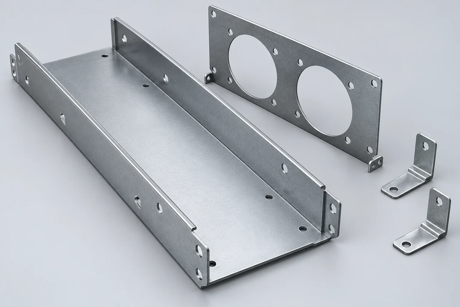
Compare the Same Four-Piece Metalwork Set
One supplier may quote a base plate; another may quote a formed tray with retention parts and hardware. The lower number may simply buy fewer things.
Hypothetical set:
- 1 main formed carrier
- 1 retaining/fan mounting plate
- 1 left-hand bracket
- 1 right-hand bracket
An order for 100 complete sets contains 100 of each fabricated part: 400 metal pieces. State whether the four parts are delivered loose or assembled and list any additional hardware separately.
Fans, connectors, PCB assemblies and control electronics are excluded from this example.
This is an illustrative purchasing unit, not an actual MSTFAB order, validated design, fixed MOQ or guaranteed delivery commitment. The cover illustrates generic metalwork, not this assembly’s engineering feasibility.
Request prices against a controlled BOM and the same finish, hardware, inspection and packing requirements. Keep part numbers and revisions visible through prototype approval and repeat orders.
Send an RFQ That Can Be Quoted
- Released STEP/STP models, dimensioned PDFs, units, revisions and the controlling document where files conflict.
- A controlled BOM separating fabricated metalwork, purchased hardware and reference-only components.
- Approved fan mounting geometry, chassis opening, guide references, insertion direction and seated position.
- Material grade, condition, thickness, finish, masking and edge requirements.
- Exact hardware, supply/installation responsibilities and delivery as loose parts or an assembly.
- Prototype and production quantities, purchasing unit, critical checks and requested reports or trial fit.
- Packing, destination and requested dates, with lead times to be confirmed in the quotation.
Illustrative RFQ wording: Please quote the empty four-piece fan carrier metalwork set from the attached released models, drawings and BOM. Confirm the finished guide envelope, retaining interfaces, hardware, finishing route and inspection scope. Identify fixture/report costs, proposed lead time, packing and exclusions separately. Fans, electronics and completed-module testing remain outside the requested metalwork scope.
If only a concept or photograph is available, say so. It can start a discussion, but production-ready geometry and acceptance requirements still need approval.
MSTFAB’s Drawing-Based Fabrication Scope
MSTFAB is operated by Guangzhou Maisituo Sheet Metal Manufacturing Co., Ltd. Its custom sheet metal fabrication scope includes formed trays, carriers, mounting plates, brackets, chassis parts and specified mechanical assemblies.
Cutting, bending, joining, hardware installation, dimensional inspection and packing are reviewed against the actual drawings and order. Suitable finishing can be coordinated with external partners to the agreed specification. Prototype and low-volume requests are evaluated by geometry, material, process and quantity, not promised from a generic carrier name.
Scope boundary: The standard metal fabrication service does not include fans, motors, electrical connectors, PCBs, fan controllers, network electronics or complete operating devices. The OEM or its qualified integrator retains airflow and thermal validation, electrical compatibility, hot-swap operation, system safety and complete-product conformity.
Public documentation and generic illustrations do not demonstrate that MSTFAB has built a particular brand’s fan module. Project-specific feasibility and any specialized test or documentation package must be confirmed before ordering.
Frequently Asked Questions
Does a metal carrier quotation include fans and electronics?
Not automatically. MSTFAB reviews drawing-defined carriers, mounting plates, brackets and agreed mechanical hardware. Fans, motors, connectors, control boards and the complete functional module are outside the standard metal fabrication scope. Identify every included item in the BOM and quotation.
Does a removable fan carrier always need welding?
No. Some designs use a cut and bent part; others need joined components or reinforcement. The approved geometry, material, forming access and mechanical requirements determine the manufacturing route. Proposed changes to the design require OEM approval.
Which material is best for a fan tray carrier?
There is no universal choice. The OEM approves the grade, thickness and finish around stiffness, mass, fastening, exposure and the equipment design. Forming feasibility, finished clearances and any required contact surfaces must also be reviewed.
Does a successful mechanical trial fit prove hot-swap compatibility?
No. It can check only the agreed mechanical interfaces represented by the sample or fixture. Electrical connection, airflow, thermal behavior, live replacement and system safety require separate OEM validation. Follow the current instructions for the actual equipment.
Does every order include a full first-article inspection report?
No automatic full-report package is promised. Agree critical dimensions, sampling, measurement condition, report format and any fixture or trial fit before approving the quotation. Dimensional inspection does not establish the completed module's cooling performance.
What should an RFQ for a custom fan tray carrier include?
Provide released STEP/STP models, dimensioned PDFs, revision and units, a controlled BOM, the fan and chassis interfaces, material and thickness, finish and hardware responsibilities. Include quantities, the purchasing unit, requested records, packing and delivery requirements.
Send the Carrier Drawings, BOM and Quantities
Share the fan and chassis references, finished dimensions, hardware and required checks. We will review the proposed metal fabrication scope and flag details to confirm before quotation.
Technical References and Editorial Notes
- Juniper Networks: PTX10004 Chassis. Router chassis components and field-replaceable fan tray context; not a drawing for a switch carrier or a claim of supplier affiliation.
- Cisco: ASR 914 Hardware Installation Guide, Installing the Cisco ASR 914 Router. See the fan tray installation and replacement sections for equipment-specific interfaces and cautions. This article is not a maintenance procedure.
These sources establish application context only. No customer relationship, endorsement or permission to copy proprietary geometry is implied. Follow current applicable documentation for the actual equipment.
Prepared with AI assistance from the supplied draft and identified references. The cover is an AI-generated structural illustration, not a real MSTFAB product photograph, approved accessory drawing, trial-fit record or thermal test. Confirm project processes, documentation and commercial terms before ordering.
 WeChat Contact
 WhatsApp Me Directly