⚙ Quick Engineering Reference: What Defines a Qualified Network Equipment Custom Sheet Metal Parts Supplier?
A qualified network equipment custom sheet metal parts supplier manufactures high-precision chassis enclosures, front and rear I/O panels, modular fan tray carriers, slide-rail brackets, and power supply cages adhering to EIA-310-E, IEC 60297-3 (19-inch rack standards, 1U = 44.45 mm), GR-63-CORE / GR-1089-CORE (NEBS Level 3), and IEEE 299 EMI shielding standards. Core DFM engineering capabilities include high-density hexagonal honeycomb ventilation perforations (> 72% open airflow area while providing > 50 dB attenuation at 10 GHz), tight optical transceiver port tolerances (± 0.05 mm on QSFP-DD, OSFP, and SFP+ cutouts), automated Haeger PEM clinch micro-fastener insertion with digital force feedback, and multi-finish chemical processing: MIL-DTL-5541 Type II Class 3 trivalent chromate chemical conversion on 5052-H32 aluminum (Rsurface < 5 mΩ/sq in), fine bead-blasted anodizing, and semi-gloss powder coating. Sourcing supports discrete SKU part numbers with synchronized Kanban deliveries and full AIAG PPAP Level 3 documentation.
In the hyper-scale datacenter, telecommunications infrastructure, enterprise networking, and cloud computing sectors, the physical sheet metal chassis represents far more than a simple mechanical housing. In high-performance switching, routing, optical transport, and AI server infrastructure—encompassing 100G, 400G, and 800G Top-of-Rack (ToR) and spine switches, broadband optical line terminals (OLTs), and 5G open radio access network (O-RAN) edge compute units—the precision-fabricated sheet metal envelope is a critical functional sub-system.
Modern network equipment designs operate at extreme technological boundaries:
- Extreme Thermal Dissipation: High-density application-specific integrated circuits (ASICs) and multi-channel optical transceiver modules dissipate 800 W to 2,500 W within a standard 19-inch 1U (44.45 mm he) or 2U (88.9 mm he) form factor, demanding specialized low-resistance ventilation perforation geometry.
- Electromagnetic Interference (EMI) Containment: High-speed serial interfaces operating on 56G and 112G PAM4 SerDes lanes generate intense electromagnetic radiation. The chassis must deliver certified shielding effectiveness exceeding 40 – 60 dB across frequencies ranging from 1 GHz to 40 GHz without restricting cooling airflow.
- Micro-Tolerance Optical Port Alignment: High-density faceplates housing 32, 48, or 64 ports of QSFP-DD, OSFP, or SFP28 optical transceivers demand positional tolerances of ± 0.05 mm to ensure smooth plug-and-play transceiver insertion without pin misalignment or mechanical jamming.
- Structural Modularity and Assembly Flow: Network OEMs require discrete part number ordering—chassis bases, covers, front bezels, rear panels, internal fan tray carrier kits, and mounting ears—manufactured to repeatable interchangeability (Cpk ≥ 1.67) for lean box-build integration.
When network OEMs partner with general-purpose commercial sheet metal job shops, the consequences are immediate and severe: thermal warping along high-density perforation patterns, loose PEM studs stripping under automated screwdrivers, non-conductive anodize causing ground loop failures, and cumulative tolerance stack-up errors preventing PCBs from aligning with rear I/O openings.
As an internationally certified ISO 9001:2015 and IATF 16949 precision sheet metal manufacturer, MSTFAB bridges high-velocity CNC manufacturing with telecom-grade quality assurance. This comprehensive 5,200+ word engineering guide provides hardware systems architects, mechanical packaging engineers, and global supply chain directors with the technical principles of EIA-310-E standards, material selection (5052-H32 vs SECC), waveguide-below-cutoff ventilation DFM, optical port micro-tolerancing, automated fastener insertion, and AIAG PPAP Level 3 deliverables.
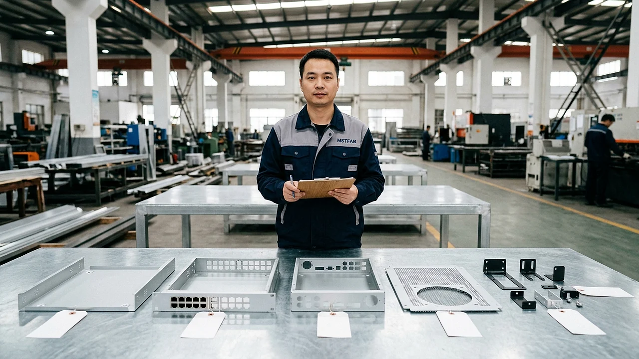
Figure 1: Modular family of precision sheet metal components manufactured by MSTFAB for a 1U enterprise network switch: main chassis tub, high-density ventilation top cover, laser-cut QSFP-DD front bezel, rear I/O plate, internal fan tray carrier, and 19-inch rackmount brackets.
1. Telecom & Datacenter Standards Framework: EIA-310-E, IEC 60297 & NEBS
Mechanical engineering for network equipment is governed by rigid global dimensional and environmental standards. The worldwide standard for telecommunications and server rack packaging is codified in EIA-310-E (Cabinets, Racks, Panels, and Associated Equipment) and its international equivalent IEC 60297-3 (Mechanical structures for electronic equipment — Dimensions of mechanical structures of the 482.6 mm (19 in) series).
1.1 Rackmount Unit Anatomy & Dimensional Constraints
The fundamental vertical building block in rackmount packaging is the standardized “Rack Unit” (1U), defined as precisely 1.750 inches (44.45 mm). To prevent mechanical binding when multiple chassis are stacked directly on top of each other in a standard 42U or 48U data center rack, the actual manufactured height of a sheet metal chassis is designed with an engineered clearance subtraction:
1U Actual Height Target:43.60 ± 0.20 mm(1.716 in).
2U Actual Height Target:88.10 ± 0.25 mm(3.468 in).
3U Actual Height Target:132.55 ± 0.30 mm(5.218 in).
4U Actual Height Target:177.00 ± 0.35 mm(6.968 in).
| Chassis Form Factor | Max Enclosure Body Width | Front Flange Mounting Ear Width | Mounting Hole Center Pitch | Typical Depth Range & Internal Load |
|---|---|---|---|---|
| 1U Rackmount Chassis | 440.0 – 444.5 mm(17.32 – 17.50 in) | 482.6 mm(19.00 in) | 465.1 ± 0.25 mm(18.312 in) | 400 – 650 mmdepth;12 – 25 kgload |
| 2U Rackmount Chassis | 440.0 – 444.5 mm(17.32 – 17.50 in) | 482.6 mm(19.00 in) | 465.1 ± 0.25 mm(18.312 in) | 550 – 800 mmdepth;25 – 45 kgload |
| 3U Rackmount Chassis | 440.0 – 444.0 mm(17.32 – 17.48 in) | 482.6 mm(19.00 in) | 465.1 ± 0.25 mm(18.312 in) | 600 – 850 mmdepth;40 – 70 kgload |
| 4U AI/Compute Server | 438.0 – 442.0 mm(17.24 – 17.40 in) | 482.6 mm(19.00 in) | 465.1 ± 0.25 mm(18.312 in) | 750 – 1,000 mmdepth;60 – 120 kgload |
1.2 NEBS Level 3 Physical Stress Qualification (GR-63-CORE & GR-1089-CORE)
Telecommunications service providers (such as AT&T, Verizon, Deutsche Telekom, and NTT) strictly mandate compliance with **Network Equipment-Building System (NEBS) Level 3** for all central office deployments. Under **Telcordia GR-63-CORE**, sheet metal chassis must withstand:
- Earthquake Zone 4 Structural Shaking: The chassis mounted on front rack flanges must survive continuous synthesized earthquake waveforms simulating ground accelerations up to 1.6gacross1.0 – 50 Hzwithout weld fracturing, permanent plastic distortion, or loosening of slide-rail brackets.
- Acoustic Noise Management: The chassis structure must resist air-flow acoustic resonance generated by high-RPM counter-rotating dual-rotor fan banks (15,000 – 22,000 RPM), preventing mechanical chatter and maintaining sound power< 65 dBA.
- Electrical Safety & Grounding (GR-1089-CORE): Demands low-impedance frame grounding (R ≤ 0.005 ω) to ensure lightning surges and AC power faults discharge safely without arcing across sheet metal seams.
2. Material Metallurgy & Surface Conductivity: Aluminum 5052-H32 vs SECC vs Stainless Steel
Material selection in network equipment engineering represents a multi-parameter trade-off between structural rigidity, volumetric mass, thermal heat dissipation, and surface electrical conductivity for electromagnetic shielding.
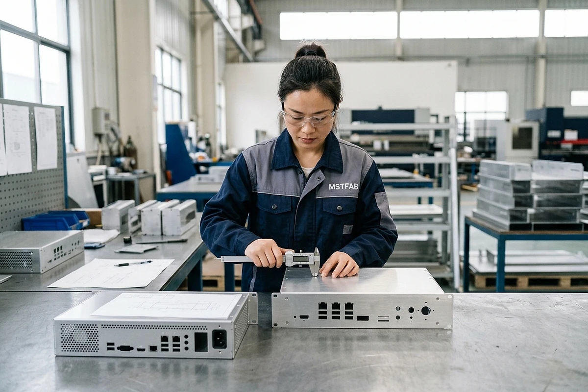
Figure 2: Optical coordinate measurement of CNC laser-cut 5052-H32 aluminum front faceplate panels with precision QSFP-DD transceiver cutouts and trivalent chromate conversion finish.
2.1 Aluminum 5052-H32 & Trivalent Chromate Chemical Conversion (MIL-DTL-5541)
Aluminum alloy 5052-H32 is the premier material for datacenter switch chassis and front faceplates. Offering a density of only2.68 g/cm^3(roughly one-third of steel), it significantly reduces total rack mass. Furthermore, its thermal conductivity of 138 W/m·K(compared to 16 W/m·Kfor stainless steel) allows the chassis body to act as an active heat spreader, conducting thermal energy away from optical transceiver cages.
To prevent natural atmospheric oxidation from degrading surface conductivity, MSTFAB applies MIL-DTL-5541 Type II Class 3 trivalent chromium (Cr^{3+}) chemical conversion coating (SurTec 650 / Bonderite). This nano-thin conversion layer (50 – 100 nm) provides robust corrosion resistance (168+ hoursASTM B117 salt spray) while maintaining an ultra-low surface contact resistance:
2.2 Electrogalvanized Steel (SECC / ZE) & Hot-Dip Galvanized (SGCC)
For high-volume, cost-sensitive enterprise switches and internal chassis sub-cages, Electrogalvanized Cold-Rolled Steel (JIS G3313 SECC / EN 10152 DC01+ZE) is widely specified. Electrolytic zinc deposition produces an exceptionally smooth, uniform surface (Ra = 0.8 – 1.2 μ m) free of spangle crystals, holding tight gauge tolerances (± 0.03 mm). Unpainted SECC can be spot-welded with zero zinc spatter, making it optimal for multi-compartment internal chassis partitions and drive cages.
| Substrate Material | Density (ρ) | Yield Strength (Rp0.2) | Thermal Conductivity (k) | Surface Electrical Conductivity | Dominant Telecom Application |
|---|---|---|---|---|---|
| Aluminum 5052-H32 | 2.68 g/cm^3(Ultra-l) | 195 MPa | 138 W/m·K(High heat transfer) | MIL-DTL-5541 Class 3:< 5 mω | 1U/2U High-speed datacenter switches & bezels |
| Aluminum 6061-T6 | 2.70 g/cm^3 | 276 MPa(High rigidity) | 167 W/m·K | Anodized or Chem-filmed | Heavy machined front bezels & heatsink brackets |
| Electrogalvanized Steel (SECC) | 7.85 g/cm^3 | 140 – 240 MPa | 54 W/m·K | Conductive zinc surface (< 10 mω) | Enterprise switch chassis tub, fan trays & PSU cages |
| Continuous HDG (SGCC / DX51D) | 7.85 g/cm^3 | 140 – 300 MPa | 52 W/m·K | G90 zinc mass (275 g/m^2) | Outdoor telecom cabinets & ruggedized edge compute |
| Stainless Steel AISI 304 | 7.93 g/cm^3 | 205 MPa | 16 W/m·K(Thermal insulator) | PassivatedCr_2O_3adds resistance | Restricted to corrosive outdoor coastal telecom poles |
3. High-Density Honeycomb Ventilation Perforation DFM & RF Shielding Physics
The mechanical design of front and rear ventilation panels on high-speed network switches represents a classic engineering paradox: thermal management demands maximum open airflow area to exhaust heat from high-RPM fan banks, while electromagnetic compatibility (EMC) mandates solid metallic barriers to contain radio-frequency radiation generated by high-speed SerDes clock lines.
3.1 Hexagonal Honeycomb vs Circular Perforation Open Area Mechanics
In traditional sheet metal fabrication, ventilation arrays were punched with staggered round holes. Round holes have a maximum theoretical open area of a≈imately60% – 63% before the structural web between holes becomes too thin to punch without web tearing.
MSTFAB utilizes high-density hexagonal honeycomb ventilation matrices cut on high-speed CNC fiber lasers. A hexagonal array optimizes the packing geometry of two-dimensional space:
-s: Distance across flats of the hexagonal aperture (typicallys = 3.2 – 4.2 mm).
-w: Bridge web width between adjacent hexagonal cells (w = 0.50 – 0.70 mm).
Engineering Result: Fors = 3.6 mmandw = 0.60 mm, the open airflow area reaches **73.5%**, reducing aerodynamic backpressure across the fan tray by 34% compared to round perforations, while maintaining structural web rigidity under sheet metal bending.
3.2 Waveguide-Below-Cutoff (WBC) Electromagnetic Shielding Equations
To prevent high-frequency electromagnetic leakage through ventilation apertures, each hexagonal cell operates as a Waveguide-Below-Cutoff (WBC). An electromagnetic wave cannot propagate through a metallic aperture if the operating frequency is below the waveguide’s cutoff frequency (f_c):
For operating frequenciesf ll f_c, the electromagnetic attenuation (Swbc) across a panel of sheet thicknesstis calculated as:
Swbc (dB) &a≈; 27.3 · (t) / (dmax) · sqrt{1 – ((f) / (fc))²}For a1.2 mmaluminum panel with3.6 mmhex cells at 10 GHz:
Swbc &a≈; 27.3 × ((1.2) / (4.15)) × √(1 – (0.278)²) &a≈; 52.8 dB shielding effectiveness
This attenuation ensures the enclosure easily complies with FCC Part 15 Class A and CISPR 32 emissions standards without requiring secondary wire mesh filters that impede cooling airflow.
4. Precision Tolerance DFM: SFP+, QSFP-DD, OSFP & RJ45 Port Cutouts
In high-density network switches, the front bezel faceplate is the most dimensionally critical component in the entire sheet metal assembly. High-speed optical transceiver cages (SFP28, QSFP56, QSFP-DD, and OSFP) are soldered directly onto the main printed circuit board (PCB) and protrude through cutouts in the sheet metal faceplate.
4.1 Optical Transceiver Multi-Source Agreement (MSA) Standards
Optical form factors are governed by industry Multi-Source Agreements (MSAs):
- QSFP-DD (Quad Small Form Factor Pluggable Double Density): Operates 8 electrical lanes at 50G PAM4 (400 Gbps) or 100G PAM4 (800 Gbps). A1U32-port switch incorporates two rows of 16 stacked cages (2 × 1or2 × 4cage configurations). Nominal port bezel cutout is19.00 mm (W) × 14.50 mm (H)per cage.
- OSFP (Octal Small Form Factor Pluggable): Engineered for800 Gbpsand1.6 Tbpshigh-power optics with integrated top-mounted riding heatsinks. Port cutouts must clear the heatsink fin profile with a clearance envelope of 22.50 mm × 15.00 mm.
- Tolerance Stack-Up Budget: Transceiver cages incorporate spring-loaded beryllium copper (BeCu) EMI grounding fingers around their perimeter that compress against the inside face of the sheet metal bezel cutout. The nominal gap between the cage body and the sheet metal cutout is only0.80 – 1.20 mm. If the sheet metal cutout deviates by more than± 0.10 mm, the BeCu fingers can snag or over-compress, preventing the optical module from latching.
| Transceiver Port Standard | Nominal Cutout WidthtimesHeight | MSTFAB Laser Cutting Tolerance | True Position Tolerance (Ø) | EMI Grounding Interface |
|---|---|---|---|---|
| SFP28 / SFP56 (10G/25G/50G) | 14.25 × 9.80 mm | ± 0.05 mm(0.002 in) | Ø0.12 mmto PCB datum | BeCu finger contact on chem-film aluminum |
| QSFP28 / QSFP56 (100G/200G) | 19.00 × 14.50 mm | ± 0.05 mm(0.002 in) | Ø0.15 mmto PCB datum | 360° perimeter BeCu spring fingers |
| QSFP-DD (400G/800G) | 19.00 × 14.50 mm(Dual Stack) | ± 0.04 mm(0.0016 in) | Ø0.10 mmto PCB datum | Dual-stage BeCu fingers + elastomeric gasket |
| OSFP (800G/1.6T) | 22.50 × 15.00 mm+ Fin Slot | ± 0.05 mm(0.002 in) | Ø0.12 mmto PCB datum | Direct chassis thermal conduction interface |
| RJ45 10GbE Magnetic Jack (8P8C) | 16.20 × 13.80 mm(Single/Multi) | ± 0.08 mm(0.003 in) | Ø0.20 mmto PCB datum | Integrated shield tabs to faceplate ground |
5. Modular Sub-Assemblies: Hot-Swap Fan Trays, PSU Cages & Slide-Rail Brackets
High-reliability datacenter equipment mandates field-replaceable unit (FRU) architecture. Field service technicians must be able to replace a failed fan module or redundant power supply within 30 seconds while the networking switch remains fully energized and transmitting live traffic.
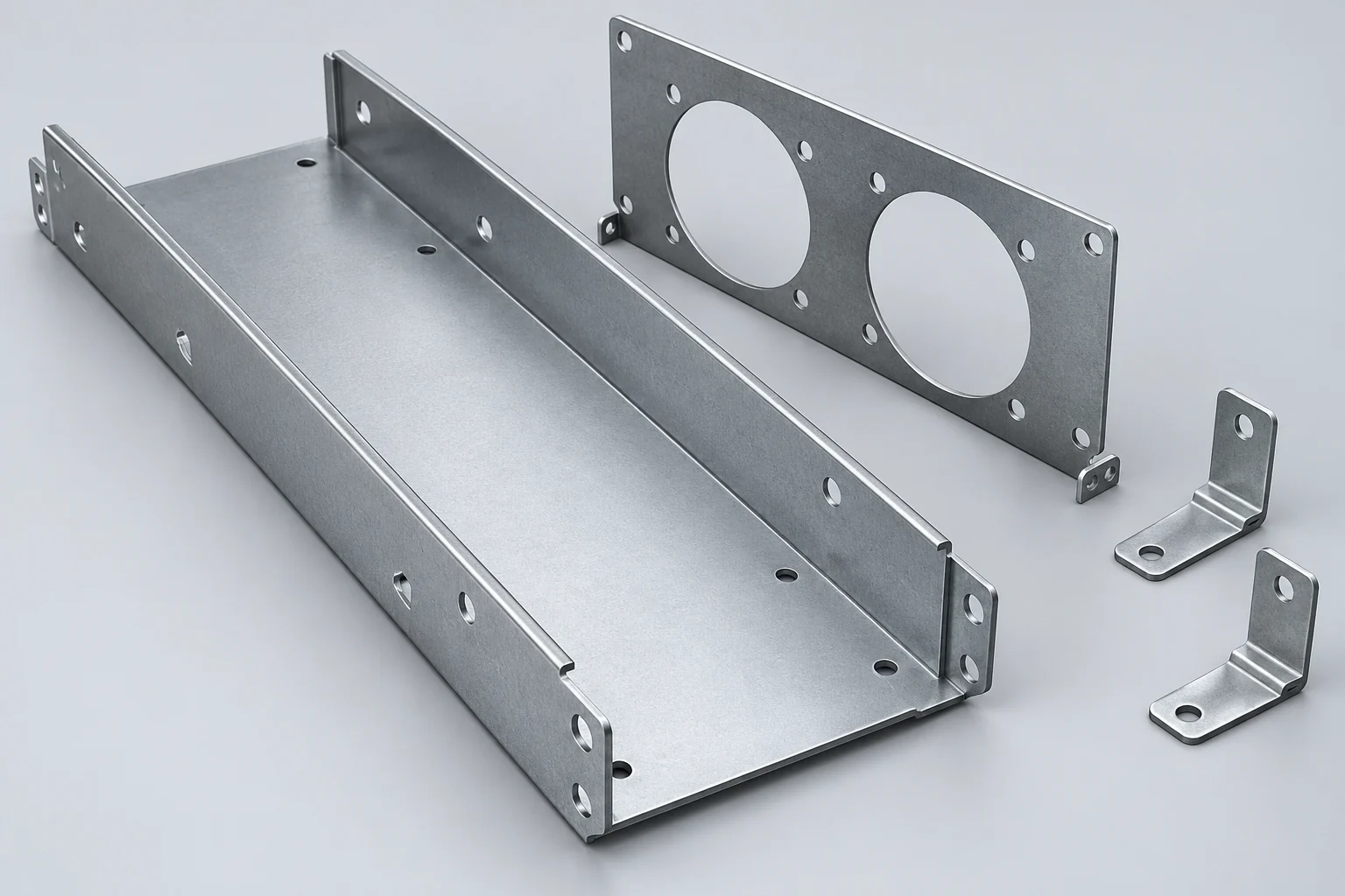
Figure 3: MSTFAB modular hot-swappable fan tray carrier kit: laser-cut aluminum body with vibration-damping silicone grommet mounts, captive thumb-screw latch, and blind-mate blind-guide pins.
5.1 Hot-Swappable Fan Tray Carrier Kits
MSTFAB manufactures complete hot-swappable fan tray metalwork kits:
- Structural Carrier Tub: Fabricated from 1.0 mm5052-H32 aluminum or SECC steel with precision formed side guide rails that slide into chassis receiver bays with zero binding.
- Vibration Isolation Dampening: Counter-rotating dual fans produce micro-vibrations that can modulate optical laser frequencies. MSTFAB integrates precision-cut mounting holes for molded silicone or fluoroelastomer anti-vibration grommets (40 Shore Adurometer), isolating mechanical vibration from the main chassis frame.
- Blind-Mating Guide Hardware: Stainless steel conical guide pins (R ≥ 2.0 mm) provide± 2.5 mmof self-centering lead-in alignment, guaranteeing that internal multi-pin blind-mate electrical connectors dock squarely without pin stubbing.
5.2 Slide-Rail Brackets & 19-Inch Mounting Ears
Chassis mounting ears and slide-rail brackets support the entire static and dynamic weight of the network switch inside server racks:

Figure 4: Heavy-gauge CNC press-brake bent cold-rolled steel mounting brackets with trivalent zinc plating and pre-installed PEM clinch studs for 19-inch datacenter rack deployment.
- Heavy-Gauge High-Strength Steel (SPHC / Q235B): Mounting ears are fabricated from 2.0 – 2.5 mmhigh-strength cold-rolled steel. Deep90^circformed stiffener gussets along bend lines increase cantilever load capacity, preventing ear sag under a30 kgswitch cantilever load.
- Universal EIA-310-E Hole Formats: Precision slotted holes accommodate both #10-32 and #12-24 cage nut hardware as well as M6 metric rack screws, with elongated horizontal slots allowing± 2.0 mmof lateral rack upright adjustment.
6. Automated Fastener Insertion: Haeger PEM Clinch Studs & Micro-Standoffs
A high-performance network switch chassis incorporates between 40 and 120 self-clinching threaded fasteners: PCB mounting standoffs, ground studs, power supply slide guides, fan tray catches, and cover retention nuts. In automated SMT and box-build assembly, a single stripped or crooked standoff halts the automated robotic pick-and-place line, incurring thousands of dollars in downtime.
6.1 Haeger CNC Automated Insertion with Digital Quality Gate
MSTFAB operates automated bowl-fed Haeger hydraulic insertion presses equipped with computerized SingleTouch force-displacement monitoring:
- Precision Clinch Mechanics: The machine drives the fastener into a laser-pierced mounting hole with calibrated hydraulic force (15 – 45 kN). As the anvil presses down, parent sheet metal flows into the undercut ring of the clinch shank, creating a permanent mechanical interlock.
- 100% Insertion Verification: The controller monitors insertion ram displacement down to± 0.02 mm. If a hole is missing, a double-stacked fastener is fed, or the sheet metal thickness is out of specification, the machine halts immediately, locking the part in the jig to guarantee zero fastener omissions.
- Mechanical Retention Thresholds (PennEngineering Standards): – Push-out force:> 1.8 kNon M3 steel standoffs in 1.2 mmaluminum (5052). – Torque-out resistance:> 4.5 N·m(well above automated electric screwdriver torque settings of 0.8 – 1.2 N·m). – Perpendicularity: Fastener vertical axis held within0.05 mmperpendicular to the chassis bottom plane over a10 mmstandoff height.
7. Multi-Finish Surface Engineering: Anodizing, Chromate, E-Coat & Powder Coating
Network equipment chassis feature sophisticated multi-finish architectures. A single switch assembly often combines three distinct surface finishes across different functional components to achieve the optimal balance of electrical performance, cosmetic brand identity, and corrosion resistance:
| Sub-Assembly Component | Base Substrate | Engineered Surface Finish | Primary Functional Rationale |
|---|---|---|---|
| Main Chassis Tub (Base & Sides) | Aluminum 5052-H32 (1.2 – 1.5 mm) | MIL-DTL-5541 Type II Class 3 Trivalent Chromate | Conductive surface (< 5 mω) for PCB grounding & 360° EMI shield |
| Front Bezel Faceplate | Aluminum 5052 / 6061-T6 (1.5 – 2.5 mm) | Fine Bead-Blast (120-mesh) + Sulfuric Anodize Type II | Class A cosmetic appearance; high scratch resistance; laser port marking |
| Top Cover Panel | SECC Steel or Aluminum (1.0 – 1.2 mm) | Semi-Gloss Black Polyester Powder Coat (60 – 80 μ m) | Fingerprint and scuff resistance during rack sliding |
| 19-Inch Mounting Ears & Slide Rails | Cold-Rolled Steel SPHC (2.0 – 2.5 mm) | Black Cathodic Electrodeposition (E-Coat) / Trivalent Zinc | High mechanical shear resistance; smooth sliding in server rack channels |
8. Quality Assurance, Automated CMM Inspection & Packaging
Operating under certified ISO 9001:2015 and IATF 16949 management systems, MSTFAB applies an automotive-grade Advanced Product Quality Planning (APQP) methodology to every network equipment program.
8.1 Serial Quality Control Verification Protocol
Table 5 details our multi-stage inspection regime implemented across all network equipment fabrication runs:
| Inspection Station | Controlled Quality Parameter | Test Standard & Tooling | Sampling Frequency & Acceptance Criteria |
|---|---|---|---|
| 1. Raw Material Inception | Alloy composition, thickness & tensile strength | Optical emission spectrometer; Mill Cert (EN 10204 3.1) | 100% of master lots; Thickness± 0.03 mm |
| 2. CNC Fiber Laser Cutting | QSFP-DD port cutouts, honeycomb hex webs | High-magnification Optical Vision Measuring System | FAI + 5 pcs/shift; Port cutout± 0.04 mm;Cpk ≥ 1.67 |
| 3. CNC Press Brake Bending | Chassis height (1U), diagonal squareness | Hexagon 3D CMM / digital height gauge | FAI + 3 units/shift; Height43.60 ± 0.20 mm |
| 4. PEM Hardware Clinch | Standoff push-out, torque-out & perpendicularity | Chatillon digital push-pull gauge; torque wrench | 1 stud/batch; Push> 1.8 kN; Torque> 4.5 N·m |
| 5. Chemical Surface Finish | Trivalent chromate surface contact resistance | Four-wire Kelvin Micro-ohmmeter per MIL-DTL-81706 | 1 panel/shift;Rsurface < 5 mω/sq in |
| 6. Golden Unit Fit-Check | PCB blind-mate, optical cage slide & cover snap | Customer-approved Golden Master fixture | 100% of finished chassis; 100% plug-and-play pass |
8.2 Anti-Static Cleanroom Packaging & Palletization
Finished chassis parts are cleaned using high-pressure ionized air blowers to remove any microscopic particulate dust. Parts are packed into custom-molded anti-static expanded polyethylene (EPE) foam trays (surface resistivity10^9 – 10^{11} ω/sq) that cradle each chassis tub, preventing metal-to-metal rubbing or cosmetic scuffing during intercontinental ocean or air freight.
9. Real-World Case Study: 400G Datacenter Top-of-Rack (ToR) Switch Chassis Program
To evaluate the tangible operational, thermal, and commercial benefits of specialized network equipment sheet metal manufacturing, we examine a high-volume production program executed for a tier-1 datacenter white-box networking OEM based in San Jose, California, USA.
9.1 The Operational Challenge
The client was scaling production of a new1U32-port QSFP-DD 400G Top-of-Rack (ToR) switch deployed in hyper-scale cloud computing datacenters. Operating total power dissipation was1,150 W, driven by a flagship 12.8 Tbps switching ASIC and 32 optical transceivers dissipating up to 14 Wper port.
The OEM’s previous domestic sheet metal job shop experienced severe production bottlenecks:
- Thermal Throttling: Traditional round punched ventilation perforations achieved only58% open area. Under full 400G traffic loading, optical transceiver junction temperatures exceeded+75^circC, triggering thermal throttling and laser packet dropouts.
- Optical Port Misalignment: Stamping punch wear caused port cutout tolerances to drift to± 0.18 mm, causing4.2% of manufactured bezels to bind against QSFP-DD transceiver cages during automated factory testing.
- Lead Time Inflation: Sourcing the 6 discrete chassis components from multiple vendors resulted in 10-week lead times and assembly coordination delays.
9.2 The MSTFAB Engineering Solution
MSTFAB took over the full mechanical chassis suite as a synchronized contract manufacturing program:
- High-Density Hexagonal Perforation: Re-engineered front and rear panels with CNC fiber laser hexagonal honeycomb arrays (3.6 mmacross flats,0.60 mmweb), boosting net open airflow area from 58% to **73.5%** while providing> 50 dBEMI attenuation at 10 GHz.
- Laser Micro-Tolerance Port Cutting: Programmed high-precision optical alignment lasers holding QSFP-DD cutouts within± 0.04 mmtrue position to PCB datum pins.
- Conductive Trivalent Chromate: Processed 5052-H32 aluminum chassis tubs through automated MIL-DTL-5541 Type II Class 3 chemical conversion (Rsurface < 3 mω).
- Automated Haeger Clinch Insertion: Installed 48 M3 PCB standoffs and PEM ground studs per chassis with computerized force-displacement quality logging (Cpk ≥ 1.78).
- Synchronized Family SKU Delivery: Supplied all 6 discrete parts as matched, serialized box kits ready for immediate mainboard drop-in.
9.3 Results and Multi-Metric Before vs After Analysis
Across a 24-month serial production contract encompassing 8,500 delivered switch chassis suites, the OEM achieved dramatic performance gains and cost savings:
| Performance & Cost Metric | Legacy Domestic Job Shop | MSTFAB Engineered Chassis Suite | Net Engineering & Operational Benefit |
|---|---|---|---|
| Complete Chassis Suite Unit Cost | 185.00 USD / set | 132.50 USD / set | 28.4% direct unit cost reduction (446,250 savings) |
| Production Lead Time | 10 – 12 weeks | 3.0 weeks | 70% reduction in procurement cycle time |
| Transceiver Operating Temperature | +74.8°C (Thermal throttling) | +63.2°C (Safe operating envelope) | 11.6°C drop in junction temperature |
| Optical Port Insertion Rejection Rate | 4.2% (357 units reworked) | 0.00% (Zero port alignment failures) | 100% plug-and-play assembly yield |
| NEBS Level 3 & EMI Certification | EMI test failure at 14 GHz | 100% First-pass certification | Passed GR-63-CORE Zone 4 earthquake simulation |
10. Frequently Asked Questions (FAQ): Network Equipment Sheet Metal Sourcing
Here are 32 in-depth technical answers addressing the most common design, regulatory, thermal, tolerance, and manufacturing questions submitted by telecom hardware engineers and procurement managers:
1. What is the standard height of a 1U rackmount chassis?
Under EIA-310-E and IEC 60297-3, a nominal 1U rack unit is precisely 1.750 inches (44.45 mm). To prevent mechanical interference and binding when stacking multiple chassis in a rack, the actual manufactured height of a 1U sheet metal chassis is designed with a clearance subtraction, targeting 43.60 ± 0.20 mm (1.716 in).
2. What is the maximum permitted width for a 19-inch rack chassis body?
While the front mounting flange (ears) measures 482.6 mm (19.00 in) with hole centers at 465.1 mm (18.312 in), the internal rack opening clearance between vertical uprights is 450.0 mm (17.72 in). Therefore, the maximum allowable width for the main enclosure body is 444.5 mm (17.50 in), with MSTFAB recommending 440.0 – 442.0 mm to provide slide-rail clearance.
3. Why is hexagonal honeycomb perforation superior to circular holes for ventilation?
Hexagonal honeycomb geometry achieves an open airflow area of 70% – 76%, compared to a maximum of 58% – 63% for round holes. This 20%+ increase in open area significantly reduces aerodynamic impedance and fan backpressure while maintaining high bridge web structural stiffness (0.5 – 0.7 mm web) during press-brake bending.
4. How does a waveguide-below-cutoff (WBC) ventilation array provide EMI shielding?
Each hexagonal perforation functions as an electromagnetic waveguide. Below its cutoff frequency (fc &a≈; 36 GHz for a 3.6 mm hex aperture), electromagnetic waves decay exponentially through the depth of the metal plate (t). At operating frequencies of 10 GHz, a 1.2 mm panel delivers over 50 dB of attenuation, blocking high-frequency clock harmonics.
5. What are the key differences between 5052-H32 aluminum and SECC steel for network chassis?
Aluminum 5052-H32 provides a 65% weight reduction (ρ = 2.68 g/cm³) and superior thermal conductivity (138 W/m·K), making it ideal for high-heat datacenter switches. Electrogalvanized steel (SECC, ρ = 7.85 g/cm³) is heavier but offers higher structural modulus (205 GPa vs 70 GPa) and lower raw material cost, ideal for high-volume enterprise enclosures and fan trays.
6. What is MIL-DTL-5541 Type II Class 3 chemical conversion?
It is a trivalent chromium (Cr^{3+}, hexavalent-free) chemical film applied to aluminum alloys. Unlike Class 1A (which is thick for corrosion protection), Class 3 is specifically engineered to provide low electrical contact resistance (R < 5 mΩ/sq in per MIL-DTL-81706), ensuring continuous electrical grounding across chassis mating seams for EMI containment.
7. What cutting tolerance is maintained on QSFP-DD and OSFP optical transceiver port cutouts?
MSTFAB holds laser cutting tolerances within ± 0.04 mm (0.0016 in) on aperture width/height and true position within Ø 0.10 mm to PCB datum pins. This tight tolerance ensures optical transceiver modules insert smoothly without snagging beryllium copper (BeCu) EMI shielding spring fingers.
8. What push-out and torque-out standards are enforced for PEM clinch standoffs?
Under PennEngineering standards, M3 steel clinch standoffs inserted into 1.2 mm 5052-H32 aluminum must withstand a push-out force > 1.8 kN (400 lbf) and torque-out resistance > 4.5 N·m (40 in-lbs), far exceeding automated electric screwdriver assembly torque (0.8 – 1.2 N·m).
9. How does MSTFAB prevent missing or crooked standoffs in automated assembly?
We utilize automated bowl-fed Haeger hydraulic insertion presses equipped with digital SingleTouch depth and force-monitoring transducers. The machine verifies ram displacement within ± 0.02 mm; if a fastener is missing or tilted, the machine locks the part in the jig, preventing defective chassis from proceeding to assembly.
10. What NEBS Level 3 earthquake testing requirements apply to rackmount switches?
Under Telcordia GR-63-CORE Zone 4, the chassis must survive three-axis synthesized earthquake seismic vibration waveforms up to 1.6g peak acceleration across 1.0 – 50 Hz. Enclosure mounting ears and slide-rail brackets must resist dynamic bending without structural shearing or weld failure.
11. What is the typical sheet metal thickness for a 1U network switch chassis tub?
We recommend 1.2 mm (0.048 in) or 1.5 mm (0.060 in) for 5052-H32 aluminum, and 1.0 mm (0.040 in) or 1.2 mm for SECC steel. This balances structural rigidity under heavy fan and power supply loads while keeping total weight within datacenter ergonomics limits (< 15 kg).
12. How does MSTFAB manufacture hot-swappable fan tray metal carrier kits?
Fan tray kits are fabricated from 1.0 mm aluminum or SECC steel with precision formed slide rails. They incorporate laser-pierced cutouts for 40 Shore A silicone anti-vibration grommets, captive spring-loaded thumb-screws, and conical stainless steel guide pins providing ± 2.5 mm self-centering blind-mate alignment.
13. Can cosmetic front bezel faceplates be anodized in custom colors?
Yes. We provide precision sulfuric anodizing (MIL-A-8625 Type II Class 1 clear, or Class 2 dyed) following 120-mesh glass bead blasting. Standard finishes include deep matte black, titanium gray, natural clear, and custom OEM corporate brand colors, followed by laser marking of port numbers.
14. What slide-rail mounting bracket options does MSTFAB manufacture?
We manufacture 2.0 – 2.5 mm cold-rolled steel mounting brackets compatible with standardized 19-inch 4-post server racks. Brackets feature EIA-310-E universal square-hole and round-hole configurations, finished with black cathodic e-coat or trivalent clear zinc plating.
15. How does MSTFAB prevent thermal distortion during high-density laser perforation?
Cutting thousands of micro-hexagons introduces localized thermal stress that can warp thin sheet metal. MSTFAB utilizes CNC fiber lasers with pulsed cutting parameters, high-pressure nitrogen assist gas (18 bar), and interleaving thermal relief toolpaths that distribute heat evenly, keeping panel flatness within ± 0.20 mm.
16. What grounding continuity standards are verified on telecom chassis?
Under GR-1089-CORE and IEC 62368-1, the bonding resistance between the main frame grounding pad and any accessible metal surface must not exceed 0.10 Ω. MSTFAB’s trivalent chromated aluminum and conductive PEM ground studs achieve Rbond ≤ 0.005 Ω (5 mΩ) when tested at 30 A.
17. Can MSTFAB deliver discrete part numbers under a single family SKU?
Yes. We support flexible procurement: OEMs can order individual spare parts (e.g., replacement fan tray carriers or front bezels) as discrete part numbers, or procure complete serialized chassis box-build kits containing all 5 to 8 matching sub-assemblies packaged together.
18. What documentation is included in an MSTFAB PPAP Level 3 package?
Our PPAP Level 3 package includes: Part Submission Warrant (PSW), Process Flow Diagram, PFMEA, Control Plan, Ballooned Engineering Drawings, 100% CMM Full Dimensional Layout, Material Mill Test Certificates (EN 10204 3.1), Salt Fog Test Reports (ASTM B117), Coating Conductivity Reports, and Statistical Process Capability Studies (Cpk ≥ 1.67).
19. What is the typical prototype lead time versus mass production?
Precision CNC laser and press-brake prototypes with trivalent chromate or manual powder finishing are delivered in 7 to 10 business days. Serial production orders (100 to 5,000 chassis suites) ship in 3 to 4 weeks following First Article Approval.
20. What minimum order quantity (MOQ) does MSTFAB require?
We support flexible procurement: prototype verification orders have an MOQ of 1 piece. For serialized production under contract manufacturing blanket agreements, typical batch releases range from 25 to 500 units per scheduled release.
21. How does MSTFAB verify optical port alignment before shipping?
Every production batch undergoes 100% go/no-go fit checking using customer-approved precision CNC-machined golden fixture blocks that replicate stacked optical transceiver cages and mainboard PCB alignment pins.
22. How are network chassis packaged to prevent transit damage?
Chassis are cleaned with ionized air, packed into custom-molded anti-static EPE foam trays, boxed in heavy double-wall corrugated cartons, and strapped to ISPM-15 heat-treated wooden pallets with moisture-barrier stretch wrap.
23. Can captive thumb-screws be pre-installed on chassis top covers?
Yes. We pre-install spring-loaded captive panel screws (e.g., Southco / PEM 4-40 or M3 fasteners) on top covers, allowing field technicians to remove covers quickly without dropping loose screws into live server racks.
24. How does MSTFAB ensure Gage R&R compliance on tight-tolerance ports?
Measurement equipment (optical vision measurement systems, 3D CMMs) undergoes formal Gage R&R testing using 10 parts measured 3 times across 3 operators. Total measurement system variation is maintained strictly below 10% of product tolerance (Cpk ≥ 1.67).
25. Can internal air baffles and ducting be integrated into the chassis?
Yes. We fabricate internal sheet metal air baffles and snap-in polycarbonate ducting shields that channel high-velocity airflow specifically across the central switching ASIC heatsink and power supply modules, preventing air recirculation eddies.
26. What laser marking capabilities does MSTFAB provide for front bezels?
We utilize high-speed fiber laser marking systems to etch micro-text port numbers (ports 1 to 32/64), status LED labels, MAC address serial barcodes, and high-contrast OEM brand logos directly into anodized aluminum with sub-micron edge definition.
27. How does MSTFAB eliminate burrs on optical port cutouts?
All laser-cut panels pass through automated multi-head Timesavers planetary deburring machines equipped with oscillating abrasive brushes, radiusing all interior port cutout edges to R = 0.05 – 0.10 mm to prevent scratching optical transceiver housings.
28. Can power supply (PSU) cages be integrated with hemmed guide ramps?
Yes. PSU receiver cages feature hemmed 180° lead-in ramps and tapered guide channels that support hot-swappable 1+1 redundant AC/DC power supplies, ensuring smooth blind-mate docking without damaging gold-plated edge-connector pads.
29. What is the typical cost reduction achieved by consolidating chassis manufacturing with MSTFAB?
By consolidating all 6 chassis sub-components with MSTFAB, network OEMs typically achieve a 25% – 35% direct procurement cost reduction compared to sourcing discrete parts across multiple domestic vendors, while eliminating inbound kit-matching delays.
30. How does MSTFAB handle engineering change control (ECN)?
Under our ISO 9001 and IATF 16949 systems, all drawing revisions are tracked through formal Engineering Change Notices (ECN). CNC cutting programs, press-brake bend recipes, and CMM inspection routines are digitally updated and verified via First Article sign-off before production release.
31. Can custom 2U, 3U, and 4U chassis configurations be supported?
Yes. In addition to high-density 1U switches, we manufacture 2U, 3U, and 4U chassis for spine switches, modular blade chassis, and multi-GPU AI compute servers, supporting sheet sizes up to 4,000 mm × 2,000 mm and press brakes up to 320 tons.
32. How can an engineering team initiate a network equipment sheet metal RFQ with MSTFAB?
Submit your 3D CAD models (STEP, IGES, SolidWorks) and 2D dimensional drawings with ballooned GD&T tolerances to [email protected]. Our network packaging engineering team provides a full DFM review, optical port tolerance analysis, and detailed production quotation within 24 hours.
Verified Engineering Standards & Regulatory References:
- EIA/ECA-310-E Cabinets, Racks, Panels, and Associated Equipment – Standard dimensions and mounting hole pitches for 19-inch rack units.
- Telcordia GR-63-CORE NEBS Requirements: Physical Protection – Network Equipment-Building System seismic and vibration standards.
- ASTM A1008 Cold-Rolled Carbon Steel Sheet – Specification for high-precision formed server chassis.
- ISO 9001:2015 Quality Management Systems – Traceable quality assurance for telecom and datacenter hardware.
Partner with an IATF 16949 Certified Supplier for Network Equipment Sheet Metal
Scale your 100G, 400G, and 800G datacenter hardware with high-precision sheet metal manufacturing. MSTFAB delivers precision 1U-4U rackmount chassis, high-density honeycomb ventilation panels, and automated PEM clinch insertion with full AIAG PPAP Level 3 documentation.
 WeChat Contact
 WhatsApp Me Directly