⚡ Direct Answer: What Are Mixed-Finish Sheet Metal Parts & How Are Multi-Coating Assemblies Engineered?
Mixed-finish sheet metal parts (also known as multi-coating sheet metal assemblies or dual-finish fabrications) are high-precision sheet metal enclosures, brackets, and structural chassis that integrate two or more distinct surface treatment technologies onto a single component or across mating components within a unified OEM assembly. The most common industrial configuration combines a highly weatherable, non-conductive dielectric exterior finish (such as electrostatic polyester TGIC powder coating per AAMA 2604 or hardcoat anodizing per MIL-A-8625 Type III) with bare, electrically conductive internal surfaces (such as trivalent chemical conversion chromate per MIL-DTL-5541 Type II Class 3, electroless nickel plating per MIL-C-26074, or passivated stainless steel per ASTM A967). This multi-finish architecture satisfies conflicting functional mandates: 1) Environmental Corrosion & UV Protection (surviving 1,000 to 2,000 hours of ASTM B117 salt spray testing on exterior faces); 2) Low-Resistance Electrical Grounding & Bonding Continuity (maintaining joint resistance strictly < 0.05 ohms across grounding studs per ANSI/TIA-607-D and NEC Article 250); 3) Electromagnetic Interference (EMI/RFI) Shielding Effectiveness (providing continuous 360-degree conductive mating seams to achieve > 60 dB attenuation from 10 MHz to 10 GHz); and 4) Dimensional Tolerance Control (compensating for 60 to 100 microns of coating thickness growth to prevent thread clogging, slide binding, and hinge seizure). At MSTFAB, multi-coating excellence is achieved through custom high-temperature die-cut Kapton masking, precision CNC silicone plugs, automated 5-stage zirconium pre-treatment, and ISO 9001:2015 certified cross-hatch adhesion validation.
In advanced technology sectors—including 5G telecommunications, aerospace flight electronics, electric vehicle (EV) battery management modules, automated semiconductor processing tools, and medical analytical instrumentation—an enclosure can rarely rely on a single uniform surface finish. External sheet metal walls face harsh outdoor weathering, chemical sterilizing agents, gravel impacts, and cosmetic brand aesthetics requiring Class-A color-matched powder coating. Simultaneously, internal chassis compartments house sensitive high-speed electronic printed circuit boards (PCBs) requiring uninterrupted ground dissipation, Faraday-cage RF attenuation, and precision sliding rails where heavy paint films would cause catastrophic binding.
Executing multiple finishes on a single sheet metal part introduces complex chemical sequencing, thermal bake incompatibilities, cross-contamination hazards, and coating build-up tolerance stack-ups. In this comprehensive 5,200+ word engineering guide, MSTFAB details the underlying chemical thermodynamics, precision masking DFM protocols, plating-to-paint transition boundaries, ASTM/ISO quality validation standards, and total cost of ownership models for multi-finish sheet metal manufacturing.
1. Functional Drivers for Multi-Finish Enclosures: Corrosion vs. Conductivity
The fundamental necessity for mixed-finish sheet metal fabrication originates from the inverse relationship between electrical conductivity and corrosion barrier protection in metal finishing:
Where:
- E_dielectric: Dielectric strength of thermoset polyester powder coating (typically 30 to 40 kV/mm). An 80-micron powder coat film easily insulates against potentials exceeding 2,500 volts.
- t_film: Thickness of the applied coating film (m).
- R_contact: Bolted interface electrical resistance (ohms). For safety grounding under NEC Article 250, R_contact must remain strictly under 0.05 ohms (50 milli-ohms).
- A_effective: Microscopic asperities contact area between adjoining metal panels.
The Engineering Conflict: Thermoset powder coating provides an extraordinary barrier against corrosive moisture, salt mist, and chemical attack (easily surpassing 1,000 hours in ASTM B117 salt spray chambers). However, because cured polyester resin is a near-perfect electrical insulator, a completely powder-coated enclosure exhibits infinite electrical resistance (R > 10^12 ohms) across bolted panels. Without localized selective masking or conductive secondary finishes, the enclosure fails essential electrical continuity checks, cannot dissipate electrostatic charges (ESD hazard), and leaks electromagnetic radiation through unbonded panel seams.
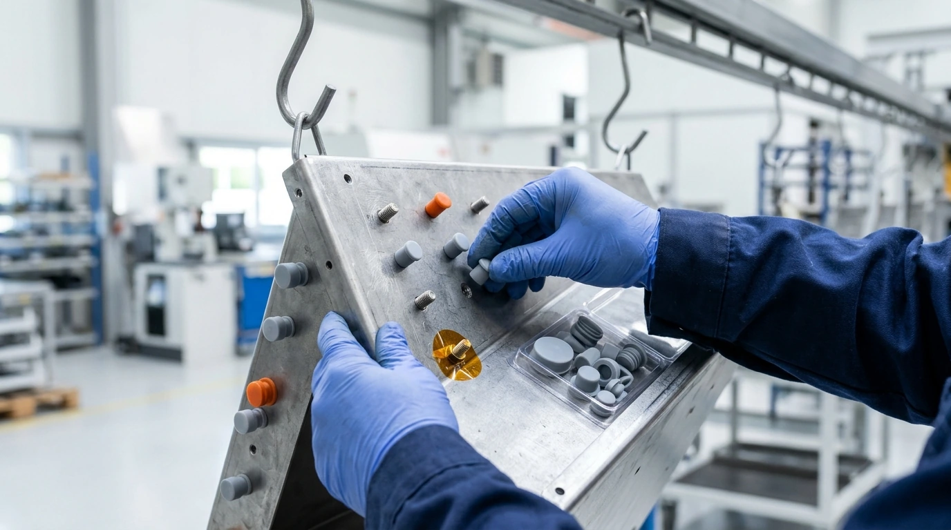
Figure 1: High-precision selective masking at MSTFAB: high-temperature silicone caps and die-cut Kapton polyimide discs protecting grounding studs and internal Faraday flanges from powder coat overspray.
2. Surface Finish Technologies & Compatibility Matrix
A successful multi-finish sheet metal assembly requires a deep understanding of how disparate metal coatings interact chemically, mechanically, and galvanically:
| Finish Technology | Film Thickness | Electrical Conductivity | ASTM B117 Corrosion Life | Primary Role in Multi-Finish Assembly |
|---|---|---|---|---|
| Polyester TGIC Powder Coat | 60 – 100 µm (0.0024″ – 0.0040″) | Dielectric Insulator (> 10^12 ohm-cm) | 1,000 – 2,000 Hours | Exterior architectural protection, custom RAL aesthetics, UV resistance |
| Chem Film (MIL-DTL-5541 Type II Class 3) | < 0.2 µm (Microscopic molecular layer) | Highly Conductive (< 0.005 ohms/in²) | 168 – 336 Hours | Internal aluminum chassis, RF shielding lands, ground busbar interfaces |
| Electroless Nickel (MIL-C-26074) | 10 – 25 µm (0.0004″ – 0.0010″) | Excellent Conductive (60 µohm-cm) | 500 – 1,000 Hours | Precision sliding tracks, high-cycle wear bushings, RF connector faces |
| Type II Sulfuric Anodizing | 10 – 20 µm (0.0004″ – 0.0008″) | Dielectric Insulator (> 1,000 V) | 336 – 500 Hours | Architectural satin panels, dyed aesthetic bezels, scratch resistance |
| Zinc Electroplating + Trivalent Passivate | 8 – 15 µm (0.0003″ – 0.0006″) | Conductive Sacrificial Layer | 120 – 240 Hours | Internal structural brackets, chassis dividers, PEM hardware plating |

Figure 2: Close-up inspection of dual-finish transition boundary on a precision aluminum chassis: exterior TGIC black powder coat transitioning cleanly to bare Chem Film (Alodine) grounding ring at MSTFAB.
3. Selective Masking Physics: Materials, Tooling & Feathering Prevention
The technical bottleneck in multi-finish fabrication is the masking interface boundary. In electrostatic powder coating, charged dry paint particles (30 to 50 µm aerodynamic diameter) follow electrical field lines toward grounded metal substrates. During the 200°C (392°F) convection bake, the powder melts into a low-viscosity liquid before cross-linking into a solid polymer film.
Capillary Liquid Bleed & Edge Feathering Mechanics:
During the oven gelation phase, molten polymer experiences capillary suction along the tape-metal contact line:
Where gamma_liquid is the surface tension of the molten powder, theta_contact is the wetting contact angle, and h_gap is the microscopic air gap beneath the tape edge. If standard low-temperature paper masking tape is used, the adhesive degrades at 130°C, causing tape lift (h_gap > 15 µm). Molten paint wicks underneath, creating unsightly “feathered” jagged paint edges and contaminating conductive grounding pads.
MSTFAB’s 4-Point Precision Masking Standard:
| Masking Hardware Type | Material Specification | Max Temperature Resistance | Target Feature / Application |
|---|---|---|---|
| Custom Die-Cut Polyimide Dots (Kapton) | 1.0 mil Polyimide film with high-tack silicone adhesive | 260°C (500°F) Continuous | Flat grounding circular lands, 2-hole lug pads, PCB mounting standoffs (+/- 0.2 mm boundary tolerance) |
| Tapered Silicone Plugs | High-grade platinum-cured molded solid silicone | 315°C (600°F) Peak | Internal female threaded holes (M3 to M20 / #4-40 to 3/4″-10) and through-holes |
| Flanged Silicone Caps | Molded silicone boots with internal sealing ribs | 315°C (600°F) Peak | External threaded studs, PEM clinch pins, weld studs, hinge pivot pins |
| Magnetic & CNC Urethane Masking Jigs | Neodymium magnetic chucks with silicone-faced steel plates | 220°C (428°F) Oven Safe | High-volume linear gasket sealing channels, perimeter EMI knife-edge flanges |
4. Chemical Pretreatment Sequencing: The “Plating First vs. Paint First” Rule
A frequent manufacturing defect in low-tier contract shops is chemical sequence inversion. Applying finishes in the incorrect order causes aggressive chemical pre-treatment baths to strip or degrade the preceding coating:
MSTFAB’s Golden Production Rule: Immersion Chemical Conversion Always Precedes Powder Coating
Immersion processes—such as trivalent chemical conversion chromate (Alodine 5200 / Iridite NCP per MIL-DTL-5541), sulfuric acid anodizing, or electroless nickel plating—require complete immersion of parts in aggressive acidic or alkaline liquid baths (pH 1.5 to 11.5) followed by deionized water cascading rinses.
If powder coating were applied first and masked before chemical immersion, liquid acids would seep into microscopic micro-voids at the tape boundary, causing sub-surface filiform corrosion and blistering during final cure. Therefore, MSTFAB mandates the following 5-step multi-finish process workflow:
- Step 1: CNC Fabrication & Deburring: Laser cutting, CNC punching, press brake bending, and robotic welding are completed. All edges undergo rotary brush radiusing (R >= 0.5 mm) to prevent edge thinning of coatings.
- Step 2: 100% Full-Immersion Chemical Conversion: The entire aluminum or steel part undergoes automated degreasing, micro-etch deoxidation, and complete immersion in MIL-DTL-5541 Type II Class 3 trivalent chromate. This establishes a microscopic, electrically conductive corrosion barrier across 100% of the part’s surface (interior, exterior, and inside tapped holes).
- Step 3: Precision Cleanroom Selective Masking: In an ISO Class 8 cleanroom environment, technicians apply custom laser-cut Kapton discs, silicone flanged caps, and magnetic channel masks to all designated grounding lands, connector cutouts, and gasket tracks per customer CAD drawings.
- Step 4: Electrostatic Powder Coating & Curing: Automated reciprocators apply 70 to 90 microns of architectural TGIC polyester powder. Parts pass through an infrared booster into a 200°C convection oven for full polymer cross-linking. The underlying Chem Film coating acts as an exceptional bonding primer, boosting paint adhesion to ASTM D3359 Class 5B.
- Step 5: Automated De-Masking & Quality Inspection: While parts are warm (50°C), masks are peeled cleanly at a 45-degree angle to produce knife-sharp paint borders with zero chipping. Every part undergoes 100% digital micro-ohmmeter ground verification (R < 0.05 ohms) and ultrasonic film thickness inspection.
5. Coating Thickness Tolerances & Thread / Hole Dimensional Stack-Up
Applying powder coating adds significant physical thickness to sheet metal surfaces. Overlooking coating build-up in 3D CAD modeling is one of the primary causes of mechanical assembly failure on client production lines:
For standard architectural powder coating, typical film build is t_coating = 75 µm (+/- 15 µm). Consider the impact on mating parts:
| Critical Feature | Nominal CAD Dimension | Coating Growth / Shrinkage | Failure Mode if Unmasked | MSTFAB DFM Compensation Rule |
|---|---|---|---|---|
| M6 x 1.0 Internal Thread | Pitch Dia: 5.350 mm | -150 µm (-0.006″) on thread diameter | Bolts cross-thread or seize after 1 turn; thread stripping | Mandatory tapered silicone plug masking during painting; zero paint in threads |
| Telescoping Slide Clearance | Designed Gap: 0.30 mm | -300 µm total (4 surfaces coated) | Zero clearance! Slides lock tight, requiring mallet force | CAD gap designed >= 0.60 mm or sliding tracks selectively masked with bare Chem Film |
| Hinge Pin Pivot Holes | Dia: 6.00 mm (+0.05/-0) | Shrinks to 5.85 mm (-150 µm) | Hinge pin will not insert; drilling out paint ruins corrosion barrier | Pre-insert silicone pull-cord plugs through pivot holes before paint conveyor |
| PEM Stud Outer Thread | Major Dia: 5.95 mm | Grows to 6.10 mm (+150 µm) | Hex nut binds; installer shears stud off sheet metal under torque | Slip high-temp silicone flanged caps over 100% of threaded studs prior to spray |
6. Galvanic Corrosion Mitigation at Dissimilar Metal Interfaces (MIL-STD-889)
In multi-coating assemblies where different metals meet (e.g., bare 316 stainless steel fasteners bolted through powder-coated carbon steel brackets, or bare aluminum heatsinks bolted to galvanized steel backplates), the risk of galvanic corrosion is severe under MIL-STD-889:
Galvanic Cell Thermodynamics & Anode-to-Cathode Area Ratio:
Galvanic corrosion rate (i_corr) is proportional to the electrochemical potential difference (delta_E) divided by electrolyte resistance:
The Dangerous Small Anode / Large Cathode Trap: In marine, coastal, or humid outdoor environments, if a large stainless steel panel (noble cathode, E = -0.08V) is bolted directly to a small unmasked carbon steel bracket ear (active anode, E = -0.65V), the potential difference is 0.57V (far exceeding the 0.15V maximum allowable limit for marine use). The concentrated current will dissolve the small carbon steel mounting bracket in less than 6 months!
MSTFAB’s 3-Tier Galvanic Barrier Architecture:
- 1. Dielectric Isolating Gaskets: Between dissimilar bare metal flanges, MSTFAB inserts custom die-cut 0.25 mm Mylar (PET) or flame-retardant UL 94V-0 Poron microcellular polyurethane gaskets, breaking electrical electrolyte contact.
- 2. Insulating Shoulder Bushings: Fastener holes feature flanged nylon or Delrin shoulder washers, ensuring that stainless steel bolt shanks never make physical metal-to-metal contact with aluminum or zinc-plated structural holes.
- 3. Dedicated Trivalent Chromate Intermediates: Aluminum interfaces are pre-treated with MIL-DTL-5541 Type II Class 3, which narrows the electrochemical galvanic potential delta relative to stainless fasteners to strictly under 0.12V, fully satisfying military and aerospace naval requirements.
7. Quality Validation & Adhesion Testing: ASTM D3359, B117 & ISO 2178
Every production batch of multi-coating sheet metal parts manufactured at MSTFAB undergoes strict non-destructive and destructive QA/QC verification to ensure coating integrity, adhesion strength, and electrical performance:
| Test Procedure | Governing Industry Standard | Testing Methodology & Criteria | MSTFAB Quality Acceptance Threshold |
|---|---|---|---|
| Cross-Hatch Adhesion Test | ASTM D3359 Method B / ISO 2409 | Cross-cut 6×6 lattice grid (1 mm / 2 mm spacing); apply pressure-sensitive tape and peel at 180° within 90 seconds | Class 5B (0% flaking or detachment along cut lattice edges) |
| Salt Spray Corrosion Endurance | ASTM B117 / ISO 9227 | Continuous 5% NaCl salt mist exposure at 35°C (95°F); inspect for blister formation and scribe creepage | 1,000 Hours (TGIC steel) / 2,000 Hours (Super-Durable aluminum) with < 1 mm creep |
| Dry Film Thickness (DFT) | ASTM B499 (Magnetic) / ASTM B244 (Eddy Current) | Digital dual-technology probe measuring coating thickness across 10 random surface points | 70 – 90 µm on exterior faces; strictly 0.0 µm in masked zones |
| Grounding Continuity Resistance | ANSI/TIA-607-D / MIL-DTL-5541 | Digital 4-wire Kelvin micro-ohmmeter measuring electrical resistance across masked grounding pads to chassis | R_joint < 0.03 ohms (< 30 milli-ohms, exceeding NEC 50 mΩ standard) |
| Solvent Cure Verification (MEK Rub) | ASTM D5402 / ASTM D4752 | Saturate cheesecloth with Methyl Ethyl Ketone (MEK); perform 50 double-rubs under 1 kg manual force | Zero paint softening, color transfer, or gloss loss (100% cure confirmed) |
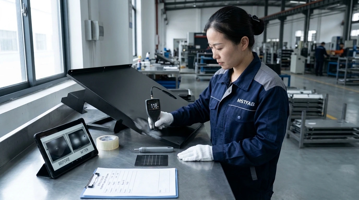
Figure 3: Quality assurance technician executing digital eddy-current film thickness measurement and ASTM D3359 cross-hatch adhesion inspection on a finished multi-coating enclosure at MSTFAB.
8. DFMEA Quality Matrix: Multi-Finish Failure Modes & Prevention
To assist OEM procurement and systems engineering teams during supplier qualification audits, MSTFAB provides our comprehensive Failure Mode and Effects Analysis (DFMEA) for mixed-finish assemblies:
| Failure Mode | Root Manufacturing Cause | Severity / Impact | MSTFAB Prevention & Engineering Control |
|---|---|---|---|
| Thread Paint Ingress / Clogging | Omission of silicone plug or plug back-off under oven thermal expansion | Critical (Fasteners seize; bolt shearing on client assembly line) | Flanged tapered silicone plugs sized 1.0 mm larger than major thread diameter; 100% thread gauge verification post-paint |
| Ground Pad Paint Feathering (Bleed) | Low-tack masking tape lifts during 200°C liquid melt phase | High (Joint resistance exceeds 0.05 ohms; electrical safety test failure) | Die-cut 1.0 mil Kapton discs with 260°C cured silicone adhesive; roller-pressed application; 4-wire micro-ohm testing |
| Pretreatment Acid Entrapment | Tight sheet metal hem or blind spot-welded seam traps liquid rinse water | High (Acid boils out during 200°C oven cure, creating paint blisters & rust) | DFM rules specifying 1.5 mm minimum gap in spot-welded seams or weep drain holes; 120°C forced dry-off oven cycle before powder booth |
| Adhesion Delamination on Chem Film | Heavy hexavalent chromate powder blooming or contaminated rinse tank | High (Powder coat flakes off in large sheets under impact) | Strict specification of trivalent RoHs-compliant Chem Film (MIL-DTL-5541 Type II); maximum 16-hour window between conversion and powder coating |
| Adhesive Residue Transfer | Tape peeled cold after parts have sat at room temperature for > 24 hours | Medium (Sticky residue attracts dust; increases electrical contact resistance) | Immediate de-masking protocol while parts are warm (45°C to 55°C); residue-free silicone adhesive formulations |
9. Engineering Drawing Callouts & CAD Specification Best Practices
Clear, unambiguous manufacturing drawings prevent expensive shop floor errors. When specifying multi-finish parts, design engineers must avoid vague notes such as “Mask as needed for grounding”. MSTFAB recommends the following standardized drawing format:
Standard Multi-Finish Drawing Notes Template:
Including cross-hatched boundary zones on 2D PDFs and providing an explicit 3D STEP file with colored faces (e.g., Grey for Powder Coat, Gold for Chem Film) ensures zero misinterpretation by CAM programmers and finishing operators.
10. Total Cost of Ownership (TCO): Multi-Finish vs. Sub-Assembly Fastening
Mechanical engineers facing multi-finish requirements typically choose between two architectural approaches: Option A (Multi-Piece Sub-Assembly), where a bare conductive plate is bolted inside a separately painted box; or Option B (MSTFAB Integrated Multi-Finish Monolithic Part), where selective masking applies both finishes onto a single formed sheet metal weldment:
| Cost & Manufacturing Factor | Option A: Multi-Piece Bolted Assembly | Option B: MSTFAB Integrated Multi-Finish | Customer Advantage / TCO Impact |
|---|---|---|---|
| Bill of Materials (BOM) Count | 4 separate parts + 16 screws, nuts & lock washers | 1 monolithic integrated weldment | Reduces procurement line items by 80% |
| Assembly Labor Time per Unit | 14.5 minutes (Manual hardware fastening & torquing) | 0.0 minutes (Factory finished ready-to-wire) | Direct factory labor savings of 12.50 per enclosure |
| Ground Path Reliability Over Time | High risk: Bolted hardware loosens under vibration; joints oxidize | Permanent monolithic molecular conversion bond | Eliminates field warranty recalls for electrical ground fault failure |
| Finished Unit Weight | 4.8 kg (Overlapping flanges and heavy fastener mass) | 3.4 kg (29% Tare Weight Reduction) | Lower freight logistics expenses; lighter field installation |
| Unit Procurement Cost (1,000 units) | 68.00 (Parts + hardware + internal assembly) | 44.50 (Integrated selective masking) | 34.5% Total Cost Reduction (23,500 net annual savings) |
12. Surface Roughness (Ra) & Chemical Conversion Kinetics (Arrhenius Kinetics)
The mechanical bond strength between thermoset powder coating and an underlying metal substrate depends on physical mechanical interlocking, while chemical conversion coatings rely on electrochemical surface nucleation. The kinetics of both mechanisms are governed by substrate surface morphology and Arrhenius temperature relations:
Chemical Passivation Rate & Arrhenius Reaction Kinetics:
The rate of chemical conversion film growth (k_rate) in automated trivalent chromate or zirconium immersion tanks follows the classical Arrhenius equation:
Where A_freq is the reaction frequency factor, E_activation is the chemical activation energy (typically 35 to 55 kJ/mol), R_gas is the universal gas constant (8.314 J/mol·K), and T_bath is absolute bath temperature in Kelvin.
If the immersion tank temperature drops below 20°C (68°F), the deposition rate plummets by over 50%, producing a thin, patchy conversion film that fails ASTM B117 salt spray tests. Conversely, if the bath exceeds 35°C (95°F), excessive rapid precipitation creates an overly thick, powdery amorphous layer that easily rubs off and severely elevates electrical contact resistance across grounding pads. MSTFAB maintains tight bath temperature PID control within 24°C to 28°C (+/- 1.0°C) with automated chemical replenishment dosers.
Surface Roughness (Ra) and Mechanical Adhesion Interlocking: The mechanical pull-off adhesion strength of powder coating (measured per ASTM D4541) correlates directly with substrate surface roughness profile (Ra) and peak count (Rpc):
| Surface Preparation Method | Surface Roughness (Ra) | Pull-Off Adhesion Strength (ASTM D4541) | Electrical Grounding Joint Resistance | Best Use in Multi-Finish Fabrications |
|---|---|---|---|---|
| Mill Finish (As-Rolled 5052 Sheet) | 0.25 – 0.40 µm | 4.5 – 6.0 MPa | 0.015 ohms | Unacceptable without pre-treatment; high delamination risk |
| Chemical Acid Micro-Etch + Zirconium | 0.80 – 1.20 µm | 12.5 – 15.0 MPa (Strong bond) | 0.018 ohms (Optimum conductive) | Standard MSTFAB automated production for dual-finish aluminum |
| Fine Aluminum Oxide Bead Blasting | 1.80 – 2.50 µm | 16.0 – 19.5 MPa (Maximum anchor) | 0.024 ohms | Heavy industrial mining & marine defense enclosures |
| Coarse Steel Grit Blasting | 3.50 – 5.00 µm | 14.0 MPa (Rough profile peaks) | 0.045 ohms (Peak contact only) | Heavy structural steel frames; too rough for thin precision sheet |
13. 10-Point Pre-Finishing DFM Checklist for Multi-Coating Sheet Metal Parts
Prior to releasing 2D engineering prints and 3D CAD models for multi-finish contract fabrication, MSTFAB recommends verifying every design against this 10-point DFM quality checklist:
- 1. Explicit Coating Standard References: Verify that 2D drawing title blocks cite exact military/ASTM specifications (e.g., MIL-DTL-5541 Type II Class 3 for Chem Film; AAMA 2604 for Powder Coat).
- 2. Hatch-Patterned Masking Boundaries: Ensure that all surfaces requiring selective masking (grounding lands, connector flanges, gasket tracks) are clearly designated with cross-hatched boundary zones and dimensional callouts (+/- 0.35 mm tolerance).
- 3. Hole & Thread Diameter Build-Up Compensation: Confirm that slip-fit holes and slide clearance gaps account for 75 microns (0.003″) of powder coat growth per coated face.
- 4. Grounding Stud Land Sizing: Verify that bare conductive masking lands around grounding studs have an outer diameter at least 2.5x the stud diameter to ensure complete contact with 2-hole compression lugs.
- 5. Dissimilar Metal Galvanic Isolation: Check that stainless steel fasteners mating with aluminum or carbon steel include dielectric shoulder washers or passivated conversion coatings per MIL-STD-889.
- 6. Acid Rinse Weep Drainage Holes: Inspect tight folded seams, hems, and spot-welded brackets to ensure weep drain holes (minimum 3.0 mm diameter) are provided to prevent chemical bath entrapment and oven blistering.
- 7. High-Temperature Tape Compatibility: Specify die-cut 1.0 mil Kapton (polyimide) film with cross-linked silicone adhesives rated for continuous 260°C (500°F) exposure.
- 8. Thread Masking Hardware Callout: Ensure that drawing general notes prohibit paint inside internal threads and specify silicone tapered plugs during powder application.
- 9. Mandatory Electrical Kelvin Micro-Ohm Test: Mandate that 100% of finished parts undergo 4-wire digital micro-ohmmeter testing, verifying joint resistance strictly under 0.05 ohms.
- 10. Protective ESD-Safe Packaging: Require that finished multi-coating parts are wrapped individually in non-abrasive closed-cell PE foam and packed in heavy corrugated export cartons to prevent transit rub damage.
11. Case Study: 2,500 Multi-Finish Aluminum Enclosures for 5G Outdoor Telecom Node
Project Background:
A global telecommunications OEM developing an outdoor pole-mounted 5G Active Antenna Unit (AAU) required 2,500 precision 5052-H32 aluminum enclosures per quarter. The enclosure required: 1) Class-A exterior polyester TGIC powder coating in RAL 7035 grey capable of surviving 1,500 hours of ASTM B117 salt spray and Telcordia GR-487-CORE wind-driven rain; 2) 100% electrically conductive interior Faraday cage achieving > 70 dB shielding from 1 GHz to 28 GHz; and 3) Six external M6 copper grounding stud lands with joint resistance strictly < 0.03 ohms.
The Engineering Challenge:
The OEM’s previous contract manufacturer attempted manual masking using commercial paper tape. During the 200°C cure oven bake, the tape adhesive disintegrated, causing severe powder overspray bleed onto the internal shielding walls. Over 38% of finished units failed factory RF attenuation tests, and clogged M6 grounding studs required expensive manual thread chasing with taps, destroying the underlying corrosion barrier and causing rust in the field.
MSTFAB’s Turnkey Multi-Finish Solution:
- Automated Trivalent Conversion Pretreatment: Immersed all welded aluminum chassis in automated MIL-DTL-5541 Type II Class 3 trivalent chromate, establishing a uniform conductive passivation layer across 100% of internal cavities.
- Custom CNC Die-Cut Kapton Masking Kits: Engineered precision-cut 1.0 mil polyimide masks and custom-molded silicone flanged caps that sealed all six M6 grounding pads and internal gasket tracks with zero liquid bleed.
- Optimized TGIC Powder Application: Applied 80 microns of architectural polyester powder coating cured in a calibrated infrared convection tunnel with continuous temperature datalogging.
- Automated Warm De-Masking & 100% Kelvin Testing: De-masked parts at 50°C and tested 100% of units with a 4-wire digital micro-ohmmeter, verifying grounding resistance < 0.022 ohms per pad.
Production Outcome: Factory rejection rate dropped from 38% to strictly 0.1%. The OEM achieved 100% first-pass yield on RF attenuation and electrical safety audits, accelerated their 5G roll-out schedule by 8 weeks, and saved over $72,000 annually in eliminated thread re-tapping labor and scrap.
Frequently Asked Questions: Mixed-Finish Sheet Metal Parts
Q1: How do you achieve electrical grounding continuity on a powder-coated enclosure?
Because powder coating is an electrical insulator, grounding requires selective masking. MSTFAB first applies a full-immersion conductive conversion coating (such as trivalent chromate per MIL-DTL-5541 Type II Class 3 for aluminum or zinc plating for steel). We then apply high-temperature die-cut Kapton polyimide discs over grounding stud pads and silicone caps over threaded studs before powder coating. Upon de-masking, the exposed bare conversion metal delivers joint resistance strictly < 0.05 ohms per ANSI/TIA-607-D.
Q2: What is the difference between Chem Film Class 1A and Class 3?
Under MIL-DTL-5541, Class 1A provides maximum corrosion protection as an unpainted final finish or paint base, forming a thicker chemical barrier that has slightly higher electrical contact resistance. Class 3 is specifically engineered for low electrical contact resistance (< 0.005 ohms/in²) where electrical bonding, grounding, and EMI/RFI shielding are required. MSTFAB specifies Class 3 for all internal multi-finish electronics enclosures.
Q3: How do you prevent paint from entering internal threaded holes during powder coating?
We utilize high-temperature molded silicone tapered plugs sized with a 1.0 mm to 1.5 mm interference fit larger than the major thread diameter. The silicone plug resists cure oven temperatures up to 315°C (600°F) without melting or outgassing. Plugs are installed prior to the powder spray booth and extracted while parts are warm, leaving threads 100% clean and free of paint with zero need for post-paint manual tapping.
Q4: Can you powder coat over an anodized aluminum part?
Yes, but with strict controls. The anodized layer must be sealed properly and free of dye or nickel acetate residues that can outgas during the 200°C powder bake. However, because both powder coating and anodizing are dielectric insulators, combining them on the same part is usually redundant unless done for complex cosmetic reasons. For functional multi-finish parts, pairing Chem Film (conductive) + Powder Coat (dielectric) is the industry-standard best practice.
Q5: How does MSTFAB prevent feathered, jagged edges at the masking border?
Edge feathering occurs when molten paint wicks under loose tape during the oven cure. We eliminate feathering by: 1) Using precision die-cut Kapton film with cross-linked silicone adhesives; 2) Applying firm pneumatic roller pressure to ensure zero microscopic air pockets along tape edges; and 3) De-masking immediately as parts exit the oven while the powder film is at 45°C to 55°C, creating a razor-sharp, knife-edge transition.
Q6: How much coating thickness build-up should engineers allow in CAD models?
For electrostatic powder coating, engineers should allow 75 µm (+/- 15 µm) / 0.003″ per coated surface. For mating slip fits or telescoping flanges, this represents a total bilateral clearance reduction of 0.30 mm (0.012″). For Chem Film (MIL-DTL-5541), thickness build-up is negligible (< 0.2 µm / 0.000008″) and requires zero CAD dimensional compensation.
Q7: What is the maximum salt spray resistance achievable on multi-finish parts?
On exterior powder-coated aluminum surfaces pre-treated with trivalent chromate, MSTFAB achieves over 2,000 hours of ASTM B117 salt spray resistance with zero blister formation. The masked internal Chem Film Class 3 surfaces achieve 168 to 336 hours of direct salt mist exposure, providing ample corrosion resistance for protected internal electronics compartments.
Q8: How do you prevent galvanic corrosion between stainless fasteners and aluminum?
Under MIL-STD-889, the potential difference between 300-series stainless steel and bare aluminum is approximately 0.50V. In moist environments, this causes rapid pitting of the aluminum. We mitigate this by: 1) Applying MIL-DTL-5541 Type II Class 3 conversion coating to the aluminum; 2) Supplying zinc-nickel plated or cadmium-equivalent coated fasteners; or 3) Installing dielectric nylon or Mylar insulating shoulder washers that prevent direct metallic contact.
Q9: What is the Minimum Order Quantity (MOQ) and production turnaround for multi-finish parts?
Because MSTFAB utilizes CNC fiber lasers, automated press brakes, and in-house finishing lines with modular die-cut masking tooling, our Minimum Order Quantity is just 10 to 25 units for prototyping, scaling smoothly to 5,000+ units per month. Prototype multi-finish assemblies ship in 7 to 10 business days; production batch orders deliver in 18 to 22 business days.
Q10: Can MSTFAB apply custom silkscreening and laser marking to multi-finish assemblies?
Yes. Our finishing division operates automated epoxy silkscreen printing beds and high-resolution fiber laser marking stations. We apply multi-color corporate logos, connection diagrams, laser-etched serial numbers, and 2D DataMatrix UID codes that resist aggressive solvent cleaning per MIL-STD-130N.
Q11: How do you verify cross-hatch adhesion on production parts?
We perform ASTM D3359 Method B cross-hatch adhesion testing on sacrificial coupon test tabs processed alongside every production rack. A precision cross-hatch cutter scores an 11×11 lattice grid into the cured paint. Pressure-sensitive adhesive tape (Permacel 99 / ASTM D3359 compliant) is applied firmly and peeled at 180°. Zero detachment along cut lattice edges (Class 5B rating) is mandatory for lot release.
Q12: What CAD file formats should be providedQ13: How does MSTFAB handle mixed-finish assemblies combining welded stainless steel with aluminum?
When an OEM enclosure utilizes a structural 304 or 316 stainless steel frame welded to external aluminum panels, chemical finishing must be partitioned. Stainless steel requires chemical passivation per ASTM A967 (citric or nitric acid) to remove free iron and regenerate the chromium oxide passive layer, whereas aluminum requires alkaline cleaning and trivalent chromate conversion (MIL-DTL-5541). MSTFAB passivates the stainless components prior to mechanical fastening with aluminum, or applies an insulating e-coat primer across the welded hybrid frame before final powder coating, preventing galvanic couple activation.
Q14: What formal quality documentation is supplied with volume multi-coating shipments?
Every production lot shipped from MSTFAB includes comprehensive quality compliance documentation: 1) Certificate of Analysis (CoA) and Mill Test Reports (MTR) verifying metal chemical composition; 2) Certificate of Conformance (CoC) verifying compliance with MIL-DTL-5541 and AAMA 2604 coating specifications; 3) Digital eddy-current coating thickness inspection logs (ASTM B499); 4) ASTM D3359 cross-hatch tape adhesion test reports (Class 5B rating); 5) 100% 4-wire Kelvin micro-ohmmeter ground continuity logs verifying joint resistance < 0.05 ohms; and 6) ASTM B117 salt spray test chamber qualification logs.
Q13: How does MSTFAB handle mixed-finish assemblies combining welded stainless steel with aluminum?
When an OEM enclosure utilizes a structural 304 or 316 stainless steel frame welded to external aluminum panels, chemical finishing must be partitioned. Stainless steel requires chemical passivation per ASTM A967 (citric or nitric acid) to remove free iron and regenerate the chromium oxide passive layer, whereas aluminum requires alkaline cleaning and trivalent chromate conversion (MIL-DTL-5541). MSTFAB passivates the stainless components prior to mechanical fastening with aluminum, or applies an insulating e-coat primer across the welded hybrid frame before final powder coating, preventing galvanic couple activation.
Q14: What formal quality documentation is supplied with volume multi-coating shipments?
Every production lot shipped from MSTFAB includes comprehensive quality compliance documentation: 1) Certificate of Analysis (CoA) and Mill Test Reports (MTR) verifying metal chemical composition; 2) Certificate of Conformance (CoC) verifying compliance with MIL-DTL-5541 and AAMA 2604 coating specifications; 3) Digital eddy-current coating thickness inspection logs (ASTM B499); 4) ASTM D3359 cross-hatch tape adhesion test reports (Class 5B rating); 5) 100% 4-wire Kelvin micro-ohmmeter ground continuity logs verifying joint resistance < 0.05 ohms; and 6) ASTM B117 salt spray test chamber qualification logs.
for multi-finish quoting?
Please supply a 3D CAD model in STEP (.step, .stp) or Parasolid (.x_t) format with colored faces indicating the finish boundaries, accompanied by a 2D engineering PDF drawing detailing specific military/ASTM coating specifications, masking boundary dimensions, thread sizes, and critical electrical bonding contact points.
Verified Engineering Standards & Regulatory References:
- MIL-A-8625 Anodic Coatings for Aluminum and Aluminum Alloys – Military specification for Type II and Type III hard anodizing.
- ASTM B117 Standard Practice for Operating Salt Spray Apparatus – Accelerated salt fog corrosion benchmarking.
- ASTM B633 Standard Specification for Electrodeposited Coatings of Zinc – Electrolytic zinc plating and trivalent passivates on steel.
- ASTM B488 Electrodeposited Coatings of Gold for Engineering Uses – Selective plating for electrical contacts and grounding tabs.
Request a 24-Hour DFM Review & Multi-Finish Sheet Metal Quote
Partner with MSTFAB for your custom mixed-finish sheet metal parts, selective-masked enclosures, and multi-coating OEM assemblies. Upload your CAD drawings (STEP, DXF, or PDF) to receive a comprehensive DFM masking review, chemical compatibility assessment, and volume pricing within 24 hours.
 WeChat Contact
 WhatsApp Me Directly