EMPTY MEDICAL EQUIPMENT ENCLOSURE DFM
Medical enclosure door bonding starts with mechanical details that are easy to postpone: attachment points, coating-free contact zones, strap clearance and a door path that does not pull the conductor tight. MSTFAB manufactures these drawing-defined sheet metal interfaces; the OEM owns the electrical design, bonding conductor and completed-equipment validation.
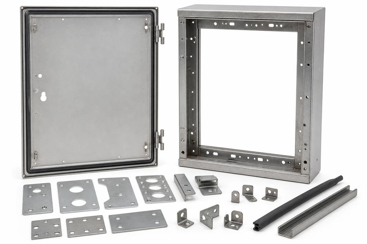
THE QUICK ANSWER
Freeze the moving interface before releasing metal
For every conductive door or removable cover that the OEM requires to be bonded, define the attachment hardware, coordinates, bare contact area, conductor envelope, opening angle, service-removal sequence and mechanical inspection method.
- Locate both attachment ends from stable functional datums.
- Model the full door arc, not only the closed position.
- Dimension thread and surface masking separately.
- Inspect the mechanical interface after welding and finishing.
Why This Page Uses a Narrower Search Intent
A separate MSTFAB guide already covers the stationary protective-earth interface on medical enclosure shells, including studs, coating masks and inspection. This page avoids repeating that subject. It concentrates on movable doors and removable covers, where hinge travel, servicing and conductor routing create a different mechanical problem.
The distinction matters. A fixed chassis stud can look perfect while a door strap becomes the world’s least successful jump rope every time the enclosure opens. The problem is not more electrical theory; it is missing mechanical information at drawing release.
Fixed geometry
Stud locations, thread, bracket shape, mask boundary and accessible tool space.
Moving geometry
Door angle, hinge axis, conductor envelope, slack and interference through the full arc.
Controlled evidence
Released drawings, first-article measurements, trial fit and approved deviations.
Begin With the Responsibility Boundary
The OEM electrical team decides whether a door or cover requires bonding, selects the conductor, defines electrical performance and validates the finished medical equipment. The sheet metal supplier should not quietly make those decisions from a photograph or a green wire shown in an assembly model.
MSTFAB can review whether the requested metal features are manufacturable and inspect whether they match the released drawing. That includes attachment location, thread, welded feature condition, mask geometry, door travel and hardware access. Electrical continuity and safety conclusions remain outside the empty-shell manufacturing scope.
| Decision | OEM or responsible integrator | MSTFAB |
|---|---|---|
| Need for bonding | Classify each door, cover and conductive part | Fabricate only the released mechanical features |
| Conductor or strap | Select part, rating, terminals and routing rules | Check drawing-defined attachment and clearance |
| Electrical acceptance | Define and perform continuity/safety validation | Provide dimensional and mechanical inspection records |
| Completed device compliance | Own risk management, testing and certification | No medical device or energized-system certification |
The 12 Mechanical DFM Checks
Panel classification
Identify every door and removable conductive cover for which the OEM requires a bonding interface.
Attachment coordinates
Dimension both ends from stable datums, not from a vague corner or cosmetic edge.
Hardware definition
State stud or insert type, thread, length, material, finish and installation method.
Edge and bend clearance
Keep hardware away from bend deformation, hems, welds and press-tool conflicts.
Conductor envelope
Provide the strap or cable outline, terminal orientation and keep-out space as mechanical inputs.
Door travel
Check the conductor envelope through the full specified opening angle and hinge motion.
Service removal
Define whether the door is removable and how a technician releases the conductor without damage.
Contact masking
Dimension the bare contact pad and thread masking separately, including tolerances.
Tool access
Reserve realistic access for washers, terminals, fasteners and installation tools.
Surface protection
Control scratches, weld spatter, coating creep, contamination and corrosion exposure.
Inspection stage
State which features are checked after welding, after coating and after mechanical trial fit.
Change control
Link the strap, hardware and shell drawings so one revision does not quietly leave the others behind.
Locate Studs From Functional Datums
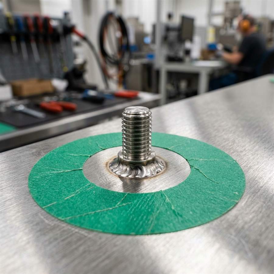
Stud position affects more than the conductor length. It also controls terminal access, wrench clearance, local panel stiffness and the risk of interference with hinges, latches, gaskets or nearby components. Dimension the feature from stable panel datums that remain meaningful after forming.
Avoid placing a welded or self-clinching feature inside the bend-affected zone. Material flow can distort the hole, tilt the feature or reduce installation reliability. Welding near a finished door edge can also create local distortion that later appears as an uneven gap.
Model the Strap as a Moving Mechanical Envelope
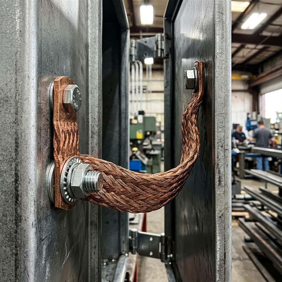
The OEM should provide the selected conductor or at least its controlled mechanical envelope: terminal geometry, hole size, width, thickness, minimum bend behavior, attachment orientation and usable length. MSTFAB uses that information to review metal-side clearance. We do not select the conductor or approve its electrical rating.
Check the envelope with the door closed, partly open and at the maximum service angle. The strap should not become taut, fold into a sharp edge, rub a gasket, cross a latch or enter the hinge pinch zone. A CAD screenshot of the closed cabinet proves only that the cabinet can pose for a photograph.
Review Door Hardware and Bonding Together
Hinges, stays, latches, gasket channels and reinforcement plates compete for the same limited door-edge space. Review them in one assembly model. If each feature is designed in isolation, the first physical prototype becomes an expensive meeting room.
Check the hinge axis, maximum opening angle, door sag allowance and terminal orientation. For a removable door, confirm the sequence for disconnecting the conductor before lifting the door away. Service access should not require a technician to balance a panel with one knee while searching for a hidden nut.

Trial Fit Before Repeat Production
A first article should use the intended material, thickness, forming route, welded features, hardware and finish whenever practical. Trial fit the door to the shell in the service orientation. Confirm opening, closing, gap, latch engagement and the buyer-defined conductor envelope.
Do not approve a movable interface using only loose parts on a table. Gravity, hinge stack-up and weld distortion join the project after assembly, usually without sending a calendar invitation.

Dimension Coating Masks, Do Not Draw a Cloud
Powder coating or paint can cover a contact area and fill threads. The drawing should define the bare pad size, location and tolerance, plus separate instructions for protecting threads. A round mask for a ring terminal should also account for washer diameter and normal placement variation.
The bare area should not be made larger simply to make masking easier. Excess exposed metal can create cosmetic and corrosion concerns. The OEM defines the functional contact requirement; MSTFAB reviews whether the specified mask is repeatable with the selected finish process.

Choose the Mechanical Attachment Route Deliberately
| Route | Mechanical advantages | DFM questions |
|---|---|---|
| Welded stud | Strong local attachment and flexible placement | Heat distortion, weld access, spatter, thread protection and post-weld location |
| Self-clinching stud | Clean installation without weld heat | Material hardness, thickness, edge distance, insertion direction and rear access |
| Weld nut or boss | Replaceable fastener route or reinforced thread | Projection, tool clearance, weld quality and coating control |
| Dedicated bracket | Moves the interface away from a crowded panel edge | Bracket stiffness, weld sequence, tolerance stack and service access |
No attachment type is universally best. The right choice depends on material, thickness, load, service cycles, finish, access and the buyer’s validated design. MSTFAB will not swap hardware types without approval because “same thread” is not the same engineering definition.
Build the Inspection Plan Around Process Risk
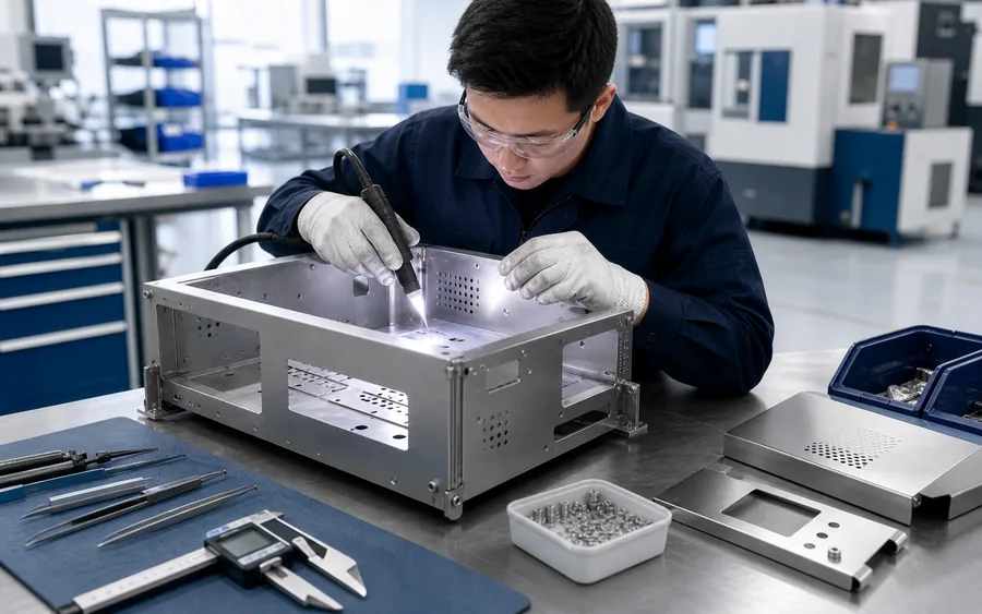
Inspect features when the relevant risk has occurred. Check stud location and panel distortion after welding. Check thread protection and contact masks after finishing. Check access and movement after the door, hinges and drawing-defined mechanical hardware are assembled.
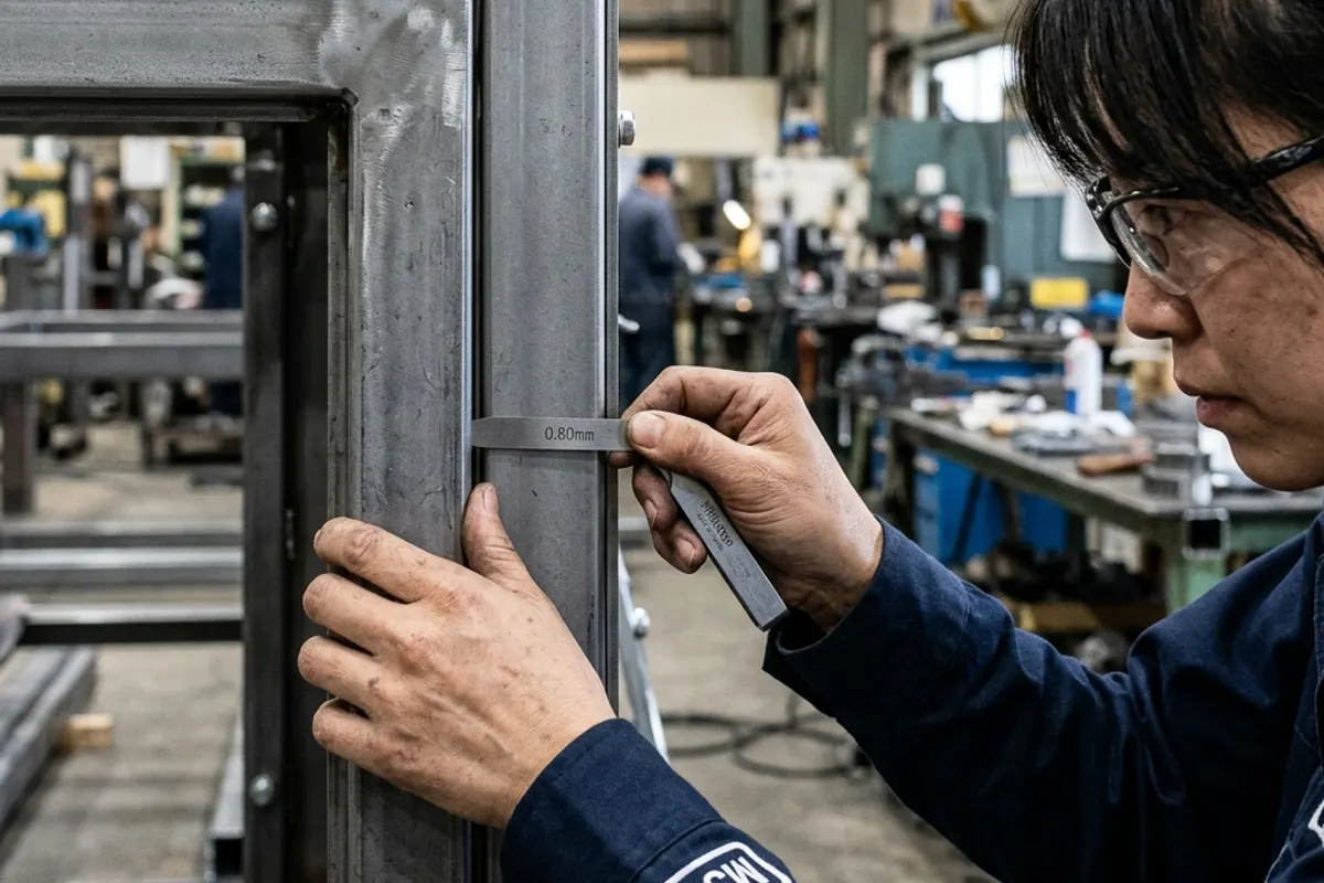
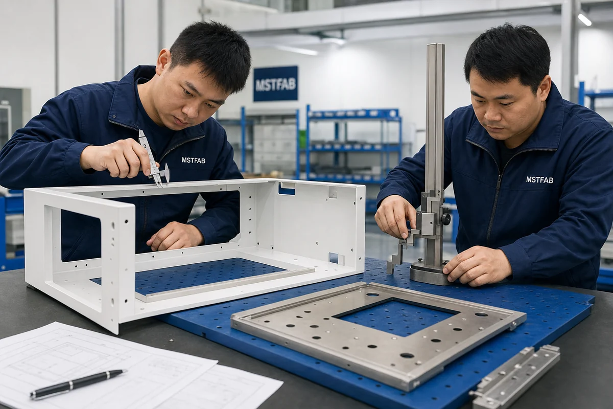
For agreed first-article characteristics, record the drawing revision, actual value, method, measuring equipment and acceptance status. Photographs can support the record, but they do not replace dimensional results. A close-up of a tape measure is not automatically metrology.

| Characteristic | Practical method | Record |
|---|---|---|
| Stud coordinates | Caliper, height gauge, fixture or CMM as tolerance requires | Actual X/Y location and datum setup |
| Thread usability | Go/no-go gauge or approved representative fastener | Thread, depth and pass/fail |
| Mask boundary | Template, scale, caliper or controlled visual standard | Size, location and coating condition |
| Door movement | Trial fit through specified angle with buyer-defined envelope | Angle, interference and service status |
| Attachment security | Buyer-specified mechanical retention or torque method | Method, limit and result |
Release One Controlled Handoff Package
The 3D model should show the assembly relationship and moving envelope. The controlled 2D drawing should define manufacturing and inspection requirements. A bill of materials should identify approved hardware. When these files disagree, the purchase order should not ask the supplier to vote.
- STEP/STP model of the shell, door, covers and relevant mechanical envelope
- Controlled PDF drawings with matching part numbers and revisions
- Material, thickness, finish and cosmetic class
- Stud or insert type, thread, length, coordinates and installation method
- Door angle, hinge axis, conductor keep-outs and service-removal sequence
- Mask sizes, locations, tolerances and thread-protection notes
- Critical dimensions, FAI format, sampling and deviation process
- Prototype and repeat-order quantities, labels and protective packing
Manage Revisions Across the Interface
A conductor change can alter terminal orientation, hole size, width or usable length. A hinge change can move the door axis. A coating change can alter masking and corrosion controls. Each change should trigger review of the linked shell, door and hardware documents.
MSTFAB retains the approved manufacturing revision and agreed inspection points for repeat production. The OEM should approve deviations and notify the supplier when interface components change. A silent component substitution is still a design change, even if procurement calls it “same same.”
Quality Systems and Medical Electrical Safety Are Different
ISO 13485 addresses quality-management-system requirements for organizations involved in medical devices. IEC 60601-1 addresses general requirements for basic safety and essential performance of medical electrical equipment. Neither title allows a sheet metal supplier to infer the OEM’s complete bonding design from an empty enclosure drawing.
MSTFAB uses controlled drawings, material identification, process records and agreed inspection evidence for the mechanical scope. The responsible medical-device manufacturer remains accountable for risk management, electrical design, test methods and final compliance of the completed equipment.
Official references: ISO 13485:2016 and IEC 60601-1 consolidated publication. Project-specific requirements should be confirmed by the responsible OEM and qualified compliance team.
Frequently Asked Questions
Does MSTFAB design the medical enclosure bonding circuit?
No. The OEM or responsible integrator defines the electrical architecture, required conductive parts, conductor and acceptance criteria. MSTFAB manufactures and inspects the drawing-defined sheet metal interfaces.
Can MSTFAB supply a welded stud and masked contact area?
Yes, when the drawing defines the stud, material, coordinates, weld or installation requirement, mask geometry, tolerance and inspection method.
Can you trial fit a customer-supplied bonding strap?
Yes, as a mechanical fit and movement check when the OEM supplies an approved sample or controlled envelope. Electrical qualification remains with the OEM.
Is a hinge automatically an acceptable bonding path?
MSTFAB does not make that electrical determination. The OEM should define whether a separate conductor is required and then release the corresponding mechanical interface.
Should the contact pad be inspected before or after powder coating?
Both stages may matter. Location and feature condition can be checked before finishing, while the final mask boundary, coating creep and thread usability should be checked after finishing.
Does ISO 13485 certification prove the finished equipment passes IEC 60601-1?
No. A quality-management system and product safety validation answer different questions. The completed device must follow the OEM’s applicable compliance plan.
Release the Door Interface Before the Prototype Teaches It to You
Send the controlled shell and door drawings, selected hardware, conductor envelope, opening angle, finish, masking and inspection requirements. MSTFAB will review the build-to-print sheet metal interface and quote the empty enclosure fabrication scope.
 WeChat Contact
 WhatsApp Me Directly