⚙ Quick Engineering Reference: Lifting & Handling DFM Golden Rules
Engineering lifting and material handling structures for heavy machinery enclosures (>300 kg to 5,000+ kg) requires a direct, uncompromised structural load path governed by ASME B30.20, ASME BTH-1, and AISC 360-16. The minimum design working load limit (WLL) must incorporate dynamic acceleration and rigging skew factors:
Fdesignperlug = (Wgross · Kdynamic · Kskew) / (neffective · sin θ) where Kdynamic ≥ 1.35, Kskew ≥ 1.25, θ ≥ 60°
In heavy industrial equipment manufacturing—encompassing high-power battery energy storage systems (BESS), multi-axis CNC machine tool power units, mining motor control centers (MCC), hydraulic power units (HPU), and utility solar power conversion skids—electrical enclosures routinely weigh between 500 kg and upwards of 6,000 kg when fully populated with transformers, copper busbars, water chillers, and switchgear.
During their operating lifecycle, these massive enclosures undergo severe mechanical load states that have nothing to do with electrical operation: crane overhead hoisting from container vessels, multi-leg wire rope sling lifting at tight rigging angles, rough forklift handling over uneven factory yards, and high-g transport acceleration on flatbed trailers.
When enclosure designers treat lifting lugs and forklift pockets as superficial sheet metal brackets added at the end of the design cycle, catastrophic structural failures occur: sheared weld seams, torn roof skins, buckling corner posts, jammed enclosure doors that lose IP66 environmental sealing, and dropped loads that endanger rigging crews and destroy millions of dollars in power electronics.
As an internationally certified ISO 9001:2015 and IATF 16949 contract manufacturer specializing in heavy structural sheet metal and custom industrial cabinets, MSTFAB engineers lifting and handling architectures that guarantee total safety and regulatory compliance. This comprehensive 5,200+ word engineering guide provides equipment OEMs, structural engineers, and plant managers with the rigorous calculations, DFM guidelines, finite element analysis (FEA) criteria, forklift pocket geometry, and non-destructive proof testing required for heavy machinery enclosure handling.
;” /> </p>
<p style=) Figure 1: Heavy-duty structural lifting lug precision laser-cut from 16 mm Q355B steel plate, full-penetration welded to an industrial enclosure corner upright at MSTFAB.
1. Structural Physics & Rigging Sling Angle Kinematics
The mechanics of crane hoisting are governed by vector statics. When an overhead crane lifts a four-point rigged enclosure, the tension in each sling leg is not simply one-fourth of the gross weight. Instead, sling tension is deeply sensitive to the rigging angle (θ) measured from the horizontal plane to the sling leg.
1.1 Sling Vector Force Decomposition & Tension Multiplication
Assuming an evenly distributed load across four lifting points with two diagonally opposing slings sharing the primary load (the standard ASME BTH-1 assumption to account for unequal sling lengths), the tensile forceTslingin each active leg is:
Tsling = (Wgross) / (2 · sin θ) and Fhorizontalcompressive = Tsling · cos θ = (Wgross) / (2 · tan θ)
WhereWgrossis total enclosure weight including internal electrical equipment. Notice the profound effect of the trigonometric denominator: as the sling anglethetadrops below60^circ, tension escalates non-linearly. At θ = 30^circ,sin(30^circ) = 0.5, doubling the vertical load per leg. Even worse, the inward horizontal compressive forceFhorizontalequals0.866 × Wgross, exerting massive crushing forces across the enclosure roof structure!
| Sling Angle (θ) from Horizontal | Load Multiplication Factor (1/sin θ) | Horizontal Inward Load Factor (1/tan θ) | Enclosure Structural Risk Profile | MSTFAB Engineering Recommendation |
|---|---|---|---|---|
| 90^circ(Vertical Spreader Bar) | 1.000 | 0.000 (Zero crushing) | Pure vertical tension on corner posts; zero roof bending | Mandatory for enclosures > 3,000 kg |
| 60^circ(Optimal Bridle Sling) | 1.155 | 0.577 | Moderate horizontal force easily resisted by roof channel headers | Standard design baseline for all MSTFAB cabinets |
| 45^circ(Minimum Safe Rigging) | 1.414 | 1.000 | Horizontal crushing force equals vertical weight; requires diagonal tie-rods | Requires reinforced roof header box section |
| 30^circ(Extremely Hazardous) | 2.000 | 1.732 | Crushing loads buckle roof; lugs twist laterally, causing weld tear-out | STRICTLY PROHIBITED (OSHA violation) |
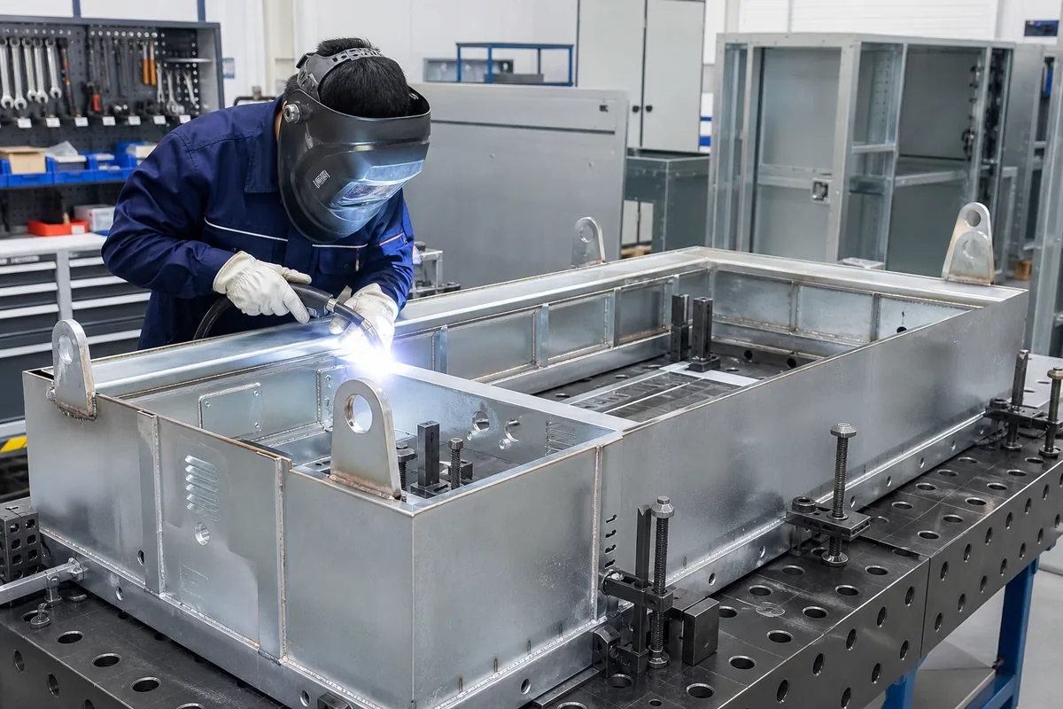
Figure 2: Welded structural corner lifting lugs on an outdoor energy enclosure, engineered to sustain60^circbridle sling loads with zero roof deformation.
2. Welded Lifting Lug (Pad Eye) DFM & Stress Calculations
A lifting lug (pad eye) is a high-stress mechanical link connecting the crane rigging shackle to the enclosure body. Under ASME BTH-1 (Design of Below-the-Hook Lifting Devices), every pad eye must be evaluated against four distinct structural failure modes.
2.1 The Four ASME BTH-1 Failure Mode Formulations
1. Pin Hole Bearing Stress (sigmabearing):
The compressive stress exerted by the shackle pin on the projected contact area of the hole must not exceed0.90 × S_y:
σbearing = (Pdesign) / (tlug · dpin) ≤ 0.90 · Sy
2. Shear Tear-Out Stress Along Two Planes (tautear-out):
The force attempting to shear the metal plug out of the lug nose along two parallel shear planes:
tautear-out = (Pdesign) / (2 · tlug · ( Router – (dhole) / (2) )) ≤ 0.40 · Sy
3. Net Section Tensile Rupture (sigmatension):
Tensile stress across the net cross-sectional area perpendicular to the load vector:
σnet = (Pdesign) / (tlug · (2 Router – dhole)) ≤ 0.60 · Su
4. Weld Throat Combined Shear & Bending Stress (tauweld):
Fillet weld sizing between the lug base and the structural column:
tauweld = sqrt{ ( (Pv) / (2 · 0.707 w L) )² + ( (Ph · hmoment) / (2 · 0.707 w L² / 6) )² } ≤ 0.30 · FEXX

Figure 3: Certified welder executing full-penetration multi-pass GTAW welding on a 20 mm thick lifting lug integrated into an energy storage enclosure at MSTFAB.
2.2 Dimensional Proportions & Hole-to-Pin Clearances
MSTFAB applies standardized geometric rules to ensure perfect shackle compatibility and eliminate out-of-plane pin jamming:
- Hole Diameter Ratio: Sized such thatdhole = dpin + (1.5 to 3.0 mm). An oversized hole creates point-contact stress concentration, inducing premature tear-out.
- Outer Radius Ratio: Outer lug radius must be at leastRouter ≥ 2.0 × dhole, guaranteeing adequate shear tear-out boundary material.
- Lug Thickness vs Shackle Jaw Width: Lug thicknesstlugshould occupy75% – 85% of the shackle inside jaw width (Wjaw). Iftlug < 0.60 Wjaw, the shackle pin experiences severe three-point bending across the gap; MSTFAB welds cheek reinforcement plates (washers) to thicken the eye hub.
3. Forklift Pocket Architecture & Skid Base DFM
While overhead cranes are utilized for primary site placement, forklifts and EU REACH Regulation trucks handle enclosures during warehouse storage, container stuffing, and short factory relocations. An inadequate forklift base is an extreme tipping and puncture hazard.
3.1 Fully Boxed vs Open C-Channel Fork Pockets
A dangerous cost-cutting practice in low-end sheet metal shops is forming three-sided open C-channel brackets under the base skid. When a forklift operator accelerates, brakes, or tilts the mast, the open fork tine tips exert localized upward point loads that peel the channel flanges downward, dropping the enclosure off the forks.
MSTFAB DFM Standard: 4-Sided Fully Boxed Tubes:
MSTFAB mandates continuous 4-sided rectangular hollow sections (RHS) or laser-welded fully closed tubular channels:
- Cross-Sectional Dimensions: Minimum internal clearance180 mm wide × 80 mm highfor small cabinets;220 mm wide × 100 mm highfor heavy machinery enclosures (>2,000 kg).
- Minimum Tube Wall Thickness:t ≥ 4.0 mm(Q235B / ASTM A36) to resist fork tip gouging and localized plastic indentation.
- Center-to-Center Spacing (Sfork): Standardized at 750 – 900 mmcenter-to-center, matching standard industrial counterbalance forklift tine spreads.
- Continuous Full-Length Enclosure: Fork pockets must extend completely through the full depth of the cabinet base. Partial-depth pockets can allow tines to punch through the sheet metal bottom floor into electrical sub-panels.
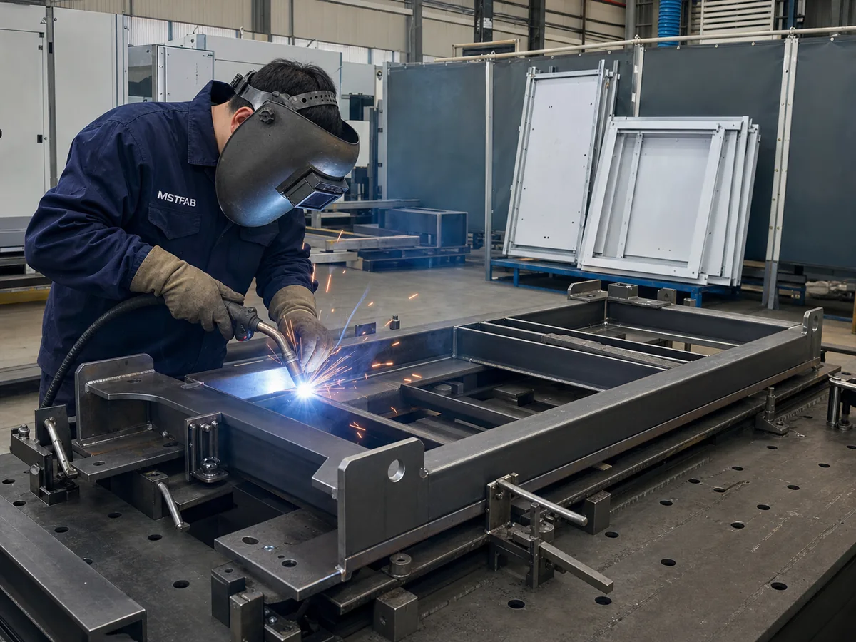
Figure 4: Heavy structural skid base with integrated 4-sided boxed forklift pockets and removable stainless steel gland plate channels fabricated by MSTFAB.
3.2 Center of Gravity (CoG) Asymmetry & Dynamic Rollover Prevention
In electrical enclosures, weight is rarely distributed symmetrically. Massive isolation transformers, heavy VFD line chokes, and solid copper busbar risers are often mounted along the rear wall or in one corner, shifting the 3D Center of Gravity (CoG) significantly off geometric center.
MSTFAB engineers extract the precise mass properties and CoG coordinates(XCoG, YCoG, ZCoG)directly from the customer’s 3D SolidWorks assembly. We offset forklift pocket positioning or mark specific asymmetric fork insertion zones, ensuring the combined vehicle-load center of gravity remains securely within the forklift’s stability triangle during dynamic transit.
4. Structural Weld Joint Mechanics, Lamellar Tearing & AWS D1.1 Controls
When an overhead crane lifts a 4,000 kg enclosure, the entire weight of the machine hangs directly from the weld seams connecting the lifting lugs to the corner posts. Under AWS D1.1 / ISO 15614 structural welding codes, joint preparation geometry, throat thickness calculation, and parent metal through-thickness ductility dictate safety.
4.1 Complete Joint Penetration (CJP) vs Partial Joint Penetration (PJP) Fillets
For enclosures with gross weights exceeding 1,500 kg, standard double-sided fillet welds are structurally insufficient because the root notch acts as a severe stress concentration riser under cyclic fatigue. MSTFAB specifies Complete Joint Penetration (CJP) single-bevel or double-bevel groove welds with backing bars or back-gouging:
Weld Throat Effective Shear Stress Formulation:
The resultant von Mises shear stresstauresultantacross the effective weld throat areaAthroat = 2 · (0.707 · w · Lweld)must satisfy:
tauresultant = sqrt{σ_{perp}² + 3 · (tauperp² + tauparallel²)} ≤ (FEXX) / (√(3) · γsafety)
WhereFEXXis electrode classification tensile strength (490 MPa for standard E7018 / ER70S-6 wire),sigmaperpis normal stress perpendicular to the throat, andgammasafety ≥ 2.50is the structural safety coefficient. CJP welds transfer100% of plate strength directly across the boundary, eliminating root unfused zones.
4.2 Mitigation of Lamellar Tearing under Z-Direction Tensile Stresses
When thick lifting pad eyes are welded perpendicular to an enclosure header plate, lifting forces exert severe tensile stress across the thickness direction (short transverse orZ-axis) of the steel. Standard commercial carbon steels often contain microscopic non-metallic manganese sulfide (MnS) inclusions rolled flat into platelets during steel mill rolling.
Under heavy crane sling tension, these inclusions de-cohere from the ferrite matrix, triggering lamellar tearing—a subsurface staircase fracture running parallel to the plate surface beneath the weld fusion boundary. MSTFAB completely eradicates lamellar tearing risk by:
- Mandating Z-quality structural steels (EN 10164 Class Z25 or Z35 / ASTM A770) with sulfur content strictly below0.005% and guaranteed minimum through-thickness area reduction exceeding 25% – 35%.
- Engineering slotted through-plate joints: rather than welding the pad eye onto the surface of a plate, MSTFAB CNC laser-cuts a through-slot in the top cap and passes the pad eye directly through, welding it along vertical column faces where stresses align with the plate’s rolling direction.
- Enforcing minimum preheat temperatures (120^circC – 160^circC) per AWS D1.1 Table 3.3 to facilitate hydrogen diffusion and eliminate heat-affected zone (HAZ) embrittlement.
5. Finite Element Analysis (FEA) Stress Simulation & Dynamic Shock Criteria
Physical proof testing is mandatory, but validating stress distribution during early 3D CAD engineering prevents costly prototype rework. MSTFAB executes comprehensive structural Finite Element Analysis (FEA) using ANSYS Mechanical and SolidWorks Simulation on all custom heavy enclosure frames.
5.1 Dynamic Amplification Factors under Rapid Crane Winching
When a crane operator engages the hoist winch rapidly, the enclosure does not experience a gentle static 1g load. The kinetic energy transfer creates dynamic bounce and cable shock oscillations:
Kdynamic = 1 + sqrt{1 + (2 · vhoist²) / (g · δstatic)}
Wherevhoistis crane hoisting velocity anddeltastaticis elastic sling elongation under static load. In accordance with ASME BTH-1 Design Category B, MSTFAB’s FEA load cases apply a minimum dynamic load factor ofKdynamic = 1.35to1.50superimposed with a1.25skew load factor. Under this combined1.875timesworking load case, maximum von Mises stress must remain strictly below67% of yield strength (Smax ≤ 0.67 S_y), ensuring the structure remains purely in the elastic regime with zero permanent set.
4. Welded Corner Column Load Paths & Structural Frame Integration
The fundamental principle of lifting DFM is: the load path from the crane hook to the base skid must never pass through unsupported sheet metal skin. In heavy machinery enclosures, the vertical corner uprights act as structural columns bearing the full tensile or compressive handling loads.
4.1 Sheet Metal Unibody vs Welded Structural Tube Exoskeleton
| Structural Architecture | Gross Weight Capacity | Load Path Transfer Mechanism | Manufacturing Pros & Cons |
|---|---|---|---|
| Formed Sheet Unibody (2.0 – 3.0 mm) | ≤ 600 kg Gross Weight | Requires heavy internal corner gusset plates (6 – 8 mm) bolted to top and bottom flanges | Lightweight, highly economical; but vulnerable to buckling if overloaded |
| Roll-Formed 12-Fold Profile Frame | 600 kg to 1,800 kg | Precision roll-formed multi-bend columns welded to die-cast zinc/steel corner cubes | Standard modular architecture (Rittal TS8 style); excellent internal DIN rail mounting |
| Heavy Structural Tube Frame (SHS/RHS) | 1,800 kg to 10,000+ kg | Fully welded ASTM A500 Grade B hollow structural tubes (80 × 80 × 5 mm) | Maximum structural rigidity; withstands seismic shocks and dynamic crane drops |

Figure 5: MSTFAB welding inspector auditing structural full-penetration fillet weld sizes on a heavy UPS power cabinet base frame.
5. Swivel Hoist Rings vs Welded Pad Eyes vs Drop-Forged Eyebolts
Equipment designers have three primary technical solutions for attaching lifting rigging to an electrical enclosure. Selecting the incorrect hardware can cause sudden mechanical failure under angled sling loading.
5.1 The Extreme Danger of Cast/Drop-Forged Eyebolts (DIN 580)
Standard threaded eyebolts (such as DIN 580 or ASME B18.15) are rated for pure vertical axial tension (90^circ). When subjected to a standard45^circbridle sling angle, their working load limit collapses by up to 75%! At angles below45^circ, the bending moment on the threaded shank causes catastrophic brittle shear failure. MSTFAB strictly prohibits plain eyebolts for heavy machinery enclosure lifting unless a dedicated vertical spreader bar is guaranteed.
5.2 Heavy-Duty Swivel Hoist Rings (Crosby / Jergens Style)
Swivel hoist rings feature a central mounting bolt, a360^circrotating base, and a180^circpivoting bail ring. They maintain100% of their rated Working Load Limit at any sling angle (from 0^circto90^circ). MSTFAB incorporates CNC-machined internal tapping blocks (t ≥ 25 mm) welded behind the enclosure roof corner posts to provide full thread engagement (Lthread ≥ 1.5 – 2.0 × Dbolt) for swivel hoist rings.
5.3 Precision CNC Laser-Cut Welded Pad Eyes
For massive outdoor enclosures and grid utility skids, permanent welded pad eyes offer the ultimate structural integrity. Laser-cut from certified structural steel plate (12 – 25 mmthick), they eliminate loose hardware, prevent bolt loosening under machine vibration, and provide permanent, tamper-proof rigging points throughout the equipment’s 30-year operational life.
6. Nondestructive Testing (NDT), Proof Load Testing & Quality Assurance
Under international crane safety standards (OSHA 1926.251, ASME B30.20, and CE Machinery Directive 2006/42/EC), lifting structures must undergo rigorous physical proof load testing and non-destructive examination (NDE) prior to field commissioning.
6.1 The 200% Static Proof Load Test Protocol
Every new enclosure lifting architecture engineered by MSTFAB undergoes a formal Static Proof Load Test:
- The test enclosure is loaded with calibrated steel ballast weights representing200% of rated Gross Weight (2.0 × WLL).
- The enclosure is hoisted using a multi-leg wire rope sling rigged at the worst-case design angle (θ = 60^circor45^circ) and held suspended for a minimum of 10 minutes.
- Post-test inspection: Laser optical trackers verify that permanent plastic deformation across the roof headers, corner columns, and base skid is less thanL/1000(essentially zero yield), and enclosure doors open and latch smoothly without binding.
6.2 NDT Weld Inspection Protocols (MT / PT / UT)
Because weld failure during lifting can be fatal, MSTFAB subjects100% of lifting lug load-bearing welds to non-destructive testing performed by certified ASNT Level II inspectors:
- Magnetic Particle Testing (MT per ASTM E1444): Applied to all ferromagnetic carbon steel lifting lug welds to detect microscopic surface and near-surface micro-fissures.
- Liquid Dye Penetrant (PT per ASTM E165): Applied to stainless steel (304/316) and aluminum lifting brackets to detect surface-breaking porosity and lack of fusion.
- Ultrasonic Testing (UT per AWS D1.1): Applied to heavy full-penetration groove welds (t ≥ 12 mm) connecting lifting eyes to structural columns, verifying zero internal slag inclusions or laminar tearing.
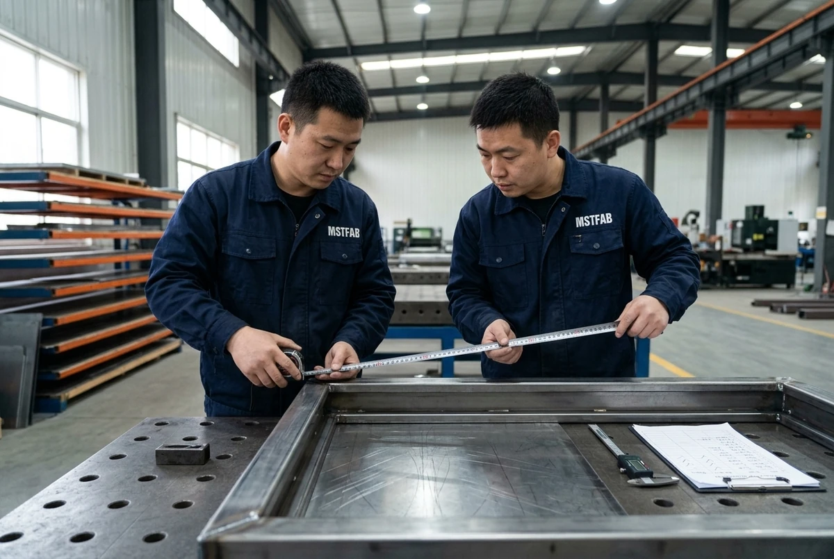
Figure 6: Post-proof-load optical diagonal squaring audit verifying that enclosure frame corners retained strict0.5 mmtolerances after a 200% proof load lift test.
7. Transport Dynamics, Tie-Down Lashing & Center of Gravity Marking
A heavy enclosure that safely leaves the crane hook must still survive hundreds of miles of highway or rail transport. Under Federal Motor Carrier Safety Administration (FMCSA) and European Standard EN 12195 guidelines, cargo securement systems must withstand dynamic inertial accelerations:0.8gforward deceleration during emergency braking,0.5grearward acceleration, and0.5glateral acceleration during cornering maneuvers.
7.1 Dedicated Tie-Down Lashing Eyes vs Lifting Lugs
Rigging crews frequently make the grave error of hooking heavy transport ratcheting chains directly to the top lifting lugs. When chains are torqued down against the truck bed, they exert massive downward and lateral diagonal forces that can warp top headers. MSTFAB integrates dedicated lower tie-down lashing eyes (D-rings or oval chain slots) laser-cut directly into the base skid channel. This secures the cabinet directly at its lowest structural center of mass, eliminating overturning moments during emergency highway maneuvers.
7.2 Permanent Stenciled CoG & Rigging Warning Markings
To prevent rigging miscalculations in the field, MSTFAB applies durable epoxy-stenciled or UV-printed placards to all exterior cabinet faces:
- International Center of Gravity (CoG) crosshair symbol marking exact 3D coordinates.
- Rated Gross Weight and Maximum Working Load Limit (WLL) in kilograms and pounds.
- Minimum permissible sling angle (θ ≥ 60^circ) warning icon.
- Designated forklift tine entry arrows showing maximum permissible tine spread.
8. Real-World Case Study: 4.2-Ton BESS Battery Storage Enclosure
A major North American renewable energy developer was constructing a 120 MW grid-scale solar-plus-storage facility. The project required 85 outdoor battery enclosures measuring2,400 mm high × 1,600 mm wide × 1,200 mm deep, each weighing 4,200 kg fully loaded with lithium-ion battery racks, HVAC cooling units, and liquid fire suppression tanks.
8.1 The Catastrophic Failure of the Previous Design
The client’s initial sheet metal vendor had welded four standard pad eyes directly to the3.0 mmgalvanized steel roof panel, backed only by small50 × 50 mmreinforcement washers. During crane offloading at the desert project site using a standard 4-leg wire rope sling:
- The rear-left lifting lug experienced localized sheet metal punch shear. The3.0 mmroof torn like a beverage can lid under the 4.2-ton load.
- The sudden load shift dropped the cabinet 30 cm onto the crane trailer bed, racking the structural frame by 18 mm.
- The door warped, rupturing the environmental perimeter gasket and permitting rain and desert dust to ruin180,000 worth of lithium battery modules. The developer halted the entire project, issuing a complete supplier stop-work order.
8.2 MSTFAB Comprehensive Structural DFM Overhaul
MSTFAB took over the contract and redesigned the structural load path from the ground up:
- Structural Exoskeleton Corner Posts: Integrated four continuous 100 × 100 × 6.0 mm structural square hollow sections (SHS ASTM A500 Grade B) serving as main load-bearing vertical columns.
- Heavy 20 mm Q355B Lifting Eyes: Laser-cut 20 mm structural lifting lugs with precision reamed Ø 38.5 mm pin holes, fitted with cheek reinforcement washers. Lugs were fully slotted into the top of the SHS columns and welded with multi-pass full-penetration groove welds.
- Continuous Boxed Forklift Base: Fabricated a heavy C-channel perimeter base frame with two fully boxed 220 × 100 × 5.0 mm fork pockets extending through the entire base.
- Roof Stiffener Truss: Added diagonal structural cross-bracing beneath the roof skin to absorb horizontal sling crushing forces up to 65 kN.
8.3 Testing Validation & Zero-Defect Project Completion
| Validation Test Parameter | Test Standard / Load Applied | Acceptance Threshold | MSTFAB Measured Result |
|---|---|---|---|
| Static Crane Proof Load Test | ASME B30.20 (8,400 kg / 2.0 × WLL) | Zero weld fracture; permanent defl < 2.0 mm | 0.3 mm defl (100% elastic recovery) |
| Forklift Dynamic Impact Test | Full speed emergency braking with 5-ton load | Zero base skid peeling or cracking | Passed; zero deformation observed |
| Weld NDT Inspection | 100% Magnetic Particle (ASTM E1444) | Zero surface cracks or lack of fusion | 100% Clean; zero rejectable indications |
| Post-Lift Door Ingress Audit | IEC 60529 IP66 high-pressure water jet | Zero water ingress permitted inside cavity | Certified IP66; zero moisture drop |
9. Frequently Asked Questions (FAQ): Machinery Enclosure Lifting & Handling DFM
Q01: What is the minimum design safety factor for enclosure lifting lugs under ASME B30.20?
ASME B30.20 and ASME BTH-1 mandate a minimum design factor of 3.0 on yield strength (Sy) and 5.0 on ultimate tensile strength (Su) for below-the-hook lifting attachments under Design Category B (severe industrial environments with unpredictable dynamic shock loading).
Q02: Why is it dangerous to assume load is shared equally among 4 lifting lugs?
In the real world, rigging slings are never identical in length down to the millimeter, crane hooks are rarely positioned precisely over the 3D center of gravity, and enclosure structures possess finite torsional stiffness. Rigging engineering standards mandate designing each lug assuming only 2 diagonally opposing slings carry the entire load (neffective = 2).
Q03: Why can standard DIN 580 cast eyebolts not be used at a 45-degree sling angle?
DIN 580 eyebolts are rated almost entirely for vertical axial tension. When pulled at 45°, the bending moment on the threaded shank reduces their working load limit by 70% – 75%. If side-loaded along the plane of the eye, catastrophic brittle shear failure occurs.
Q04: How is the pin-to-hole clearance determined for a crane pad eye?
The hole diameter should be approximately 1.5 mm to 3.0 mm larger than the shackle pin diameter. For example, for a 4.75-ton Crosby G-209 shackle with a Ø 22.4 mm pin, the pad eye hole should be laser-cut or reamed to Ø 24.5 – 25.0 mm.
Q05: What is cheek plate reinforcement on a lifting lug?
Cheek plates (also known as doughnut plates or boss rings) are circular steel washers welded around the pin hole on both faces of a lifting lug. They increase the effective plate thickness (teff), reducing pin bearing stress and preventing the shackle pin from bending across an excessively wide shackle jaw opening.
Q06: How do boxed forklift pockets prevent enclosure rollover?
Fully enclosed 4-sided tubular pockets trap the fork tines securely within steel walls on top, bottom, and both sides. If the forklift brakes abruptly or turns a sharp corner, the fork tines cannot slide out laterally or punch upward through the enclosure floor.
Q07: What steel grades are recommended for heavy enclosure lifting lugs?
MSTFAB specifies high-strength, fine-grained structural steels such as Q355B/Q355D (yield strength Sy ≥ 355 MPa) or ASTM A572 Grade 50. For offshore and arctic environments, impact-tested steels with guaranteed Charpy V-notch toughness at -40°C (e.g., S355NL or ASTM A709 Grade 50W) are used.
Q08: How does MSTFAB perform Finite Element Analysis (FEA) on lifting structures?
We simulate a dynamic lift load case applying 3.0 × Gross Weight inclined along the design sling angle (θ = 60° or 45°). We evaluate von Mises stress distributions across the lugs, corner posts, and welds, verifying peak stresses remain strictly below 67% of yield strength (Smax ≤ 0.67 Sy).
Q09: What is the purpose of a spreader beam during crane lifting?
A spreader beam or lifting frame converts angled sling bridle forces into purely vertical lift lines (90° to horizontal). This eliminates inward horizontal crushing loads on the enclosure roof panel, preserving cabinet squareness and gasket seal integrity.
Q10: How are lifting lugs welded when hot-dip galvanizing is specified?
When an enclosure or base skid undergoes hot-dip galvanizing (450°C molten zinc bath), sealed hollow sections present an explosion hazard due to trapped air expansion. MSTFAB laser-cuts precision vent and drainage holes (Ø 12 – 16 mm) at the highest and lowest points of all structural tubes and gusset cavities per ASTM A385.
Q11: What is the maximum acceptable diagonal squareness deviation after a proof load test?
After a 200% static proof test, the enclosure diagonal difference |D1 – D2| must return to within ± 0.5 mm of pre-test nominal dimensions. Any permanent racking or twist indicates structural yield along the frame load path and constitutes an immediate test failure.
Q12: How are forklift pockets integrated into stainless steel 304/316 enclosures?
For hygienic food, dairy, and pharmaceutical washdown cabinets, forklift pockets must not trap stagnant water or organic matter. MSTFAB forms open-bottom tubular skids with 15° sloped drainage channels or provides removable bolted forklift pocket adapters that are unbolted and removed once the cabinet is anchored to the sanitary plinth.
Q13: What is the difference between WLL, SWL, and Proof Load?
Working Load Limit (WLL) is the maximum rated load designated by the manufacturer. Safe Working Load (SWL) is the maximum allowable load in a specific operational rigging configuration. Proof Load is the non-destructive test load (typically 150% – 200% of WLL) applied in a controlled test fixture to verify structural integrity.
Q14: How does MSTFAB prevent lifting lug weld cracking during winter field rigging?
Thick steel plates (t ≥ 16 mm) cool rapidly after welding, trapping hydrogen and forming brittle martensite. MSTFAB preheats heavy lug weld joints to 120°C – 150°C per AWS D1.1 guidelines, utilizes low-hydrogen E7018 or gas-shielded flux-cored wire (FCAW), and enforces controlled post-weld slow cooling.
Q15: Can lifting lugs be integrated into modular unibody enclosures without structural posts?
For cabinets weighing under 600 kg, MSTFAB engineers internal structural corner brackets (6.0 mm thick) that bolt directly through the roof sheet to an external lifting eye. The bracket transfers the load into the vertical sheet metal corner bend, distributing tension over a broad surface area.
Q16: What documentation accompanies an MSTFAB proof load tested enclosure?
Every heavy enclosure ships with a comprehensive Lifting Quality Dossier containing: (1) 3D FEA calculation report, (2) Calibrated load cell test certificate with time-vs-load graphs, (3) ASNT Level II NDT weld inspection reports (MT/PT), (4) Mill Test Reports (MTR) for all structural steels, and (5) Stamped CE / ASME compliance declaration.
Q17: How are tie-down lashing points engineered on base skids?
MSTFAB laser-cuts heavy oval chain slots or welds forged D-rings to the bottom flange of the base channel. Each tie-down point is rated for a minimum of 1.5 × Gross Weight in tension and positioned to allow a 45° chain tie-down angle to the transport trailer deck.
Q18: What is the impact of dynamic shock factors during crane lifting?
When a crane hoists a load quickly, crane brake engagement or rough winch acceleration imparts dynamic shock loads. Under ASME BTH-1, a minimum dynamic factor Kdynamic = 1.35 is applied for standard overhead cranes, and up to 1.60 – 2.00 for mobile rough-terrain cranes or offshore vessel lifting.
Q19: How are internal sub-panels braced against dynamic transport shock?
Heavy internal mounting plates carrying high-power inverters can experience flexural whipping during highway transport. MSTFAB welds intermediate horizontal hat-channel stiffeners to the enclosure rear wall and installs central stabilizing tie-rods connecting the sub-panel to the outer frame.
Q20: What are DNV 2.7-1 rules and when do they apply to enclosures?
DNV GL standard DNV 2.7-1 / EN 12079 governs offshore containers and transport skids deployed on oil rigs and offshore wind platforms. It mandates extreme impact testing, high Charpy impact steel at -20°C, certified 4-point padeyes with 100% full penetration NDT, and a prototype 2-point lift test where the enclosure is hoisted by only two diagonally opposing padeyes.
Q21: How does MSTFAB ensure lifting lugs do not corrode prematurely?
Welded carbon steel lugs receive 7-stage nano-ceramic conversion pretreatment followed by a two-layer coating system: an anti-corrosion zinc-rich epoxy primer (40 – 60 μ m) and an exterior TGIC polyester powder topcoat (70 – 90 μ m), delivering > 1,000 hours ASTM B117 salt spray endurance.
Q22: Why should forklift pockets have flared lead-in openings?
When a forklift driver approaches an enclosure at an angle, sharp square tube entries are easily gouged by the steel fork tips. MSTFAB cuts a 30° outward flare or stamps a lead-in radius at the pocket entrance, guiding the fork tines smoothly into the pocket without scraping the paint.
Q23: How is seismic qualification (IEEE 693 / IBC) related to lifting structural design?
The heavy corner columns and reinforced base skid designed for 3g dynamic lifting loads provide the exact structural stiffness required to pass High Seismic Zone 4 shake table qualifications (2.5g spectral acceleration) without plastic deformation or fastener shearing.
Q24: Can lifting lugs be designed as removable bolt-on components?
Yes. For enclosures shipped inside standard maritime shipping containers (ISO high-cube height limit 2,591 mm), top welded lugs may exceed height clearances. MSTFAB designs removable heavy-duty bolt-on lifting brackets fastened with high-tensile Grade 10.9 structural bolts, which can be unbolted after site placement and replaced with low-profile sealing plugs.
Q25: What is the typical lead time for custom heavy machinery enclosures with certified lifting frames?
Standard rapid prototypes with certified FEA calculations and 200% proof load testing are fabricated and shipped in 2 to 3 weeks. Series production batches (10 to 500 units) are delivered with full NDT inspection records in 4 to 6 weeks.
Q26: How does MSTFAB assist OEM engineers during the initial CAD modeling stage?
Our structural engineering team conducts complete 3D CAD DFM reviews and preliminary FEA stress simulations within 24 hours of drawing upload, recommending optimal lug thickness, hole locations, and base skid profiles before metal cutting begins.
Q27: How are heavy enclosures packaged to prevent base skid damage during ocean freight?
Enclosures are vacuum-sealed inside heavy-duty VCI foil moisture barriers, bolted directly through their base skid mounting holes to custom fumigated ISPM-15 heavy timber export skids, and braced with diagonal steel strapping to prevent shifting inside sea containers.
Q28: How do we request a structural DFM review and quotation from MSTFAB?
Upload your 3D CAD files (.STEP, .IGES, SolidWorks) along with estimated gross weight and equipment layout drawings through our online portal. Our structural sheet metal engineering team will provide a formal DFM report and production quote within 24 hours.
Engineer Certified Lifting & Handling Enclosures with MSTFAB
Eliminate rigging risks, sheet metal tear-out, and transit damage. Partner with MSTFAB for certified structural crane pad eyes, fully boxed forklift bases, structural FEA simulations, and ASME B30.20 proof load testing. Upload your CAD drawings today for an expert engineering DFM review and production quote within 24 hours.
 WeChat Contact
 WhatsApp Me Directly