Precision sheet metal fabrication relies on a unified manufacturing triad: fiber laser cutting, CNC press brake bending, and structural welding. In modern OEM equipment manufacturing—spanning telecommunications subracks, medical diagnostic consoles, industrial automation cabinets, and energy storage enclosures—these three processes cannot operate in isolated silos. Dimensional variations introduced at the laser cutting stage directly dictate press brake backgauge repeatability, while flange angular accuracy dictates weld joint gap consistency and thermal distortion behavior. As an ISO 9001:2015 and ISO 13485:2016 certified sheet metal supplier, MSTFAB delivers an integrated, closed-loop fabrication ecosystem that unifies micron-level fiber laser cutting, dynamic angle-compensated bending, robotic laser/TIG welding, and automated hardware insertion under a single roof.
Table of Contents
- 1. The Integrated Fabrication Triad: Closed-Loop Engineering
- 2. High-Precision Fiber Laser Cutting: Optics, Assist Gases, and Kerf Dynamics
- 3. Automated Nesting, Grain Direction, and Common-Line Cutting (CLC)
- 4. CNC Press Brake Forming: Bending Physics, K-Factors, and Crowning Compensation
- 5. Precision Welding Engineering: TIG, Cold Metal Transfer (CMT), and Robotic Laser
- 6. Thermal Shrinkage and Residual Stress Management in Sheet Metal Welding
- 7. Design for Manufacturability (DFM): Inter-Process Tolerance Budgets
- 8. Secondary Value-Add: Haeger Clinching, Deburring, and Surface Finishing
- 9. Quality Assurance: CMM Verification, Weld Macro-Etching, and FAI Documentation
- 10. Comprehensive Engineering Data Matrices and Performance Benchmarks
- 11. Real-World OEM Case Studies and Validated Performance Metrics
- 12. Frequently Asked Technical Questions (32 Detailed Engineering Q&As)
1. The Integrated Fabrication Triad: Closed-Loop Engineering
When OEMs source laser-cut blanks from one vendor, send them to a second shop for press brake forming, and transfer formed parts to a third subcontractor for welding, tolerance stack-up and finger-pointing are inevitable. An out-of-square welded frame is rarely caused by poor welding technique alone; it is typically the cumulative result of an uncompensated laser cut taper, improper bend deduction software assumptions, and cumulative flange length drift.
MSTFAB solves this systemic manufacturing failure mode through an integrated closed-loop CAD/CAM ecosystem:
- Single-Source Digital Continuity: Native 3D CAD files (STEP, SolidWorks, Autodesk Inventor) are unfolded using proprietary material bending libraries calibrated to our specific press brake V-die geometries, sheet grain directions, and metallurgical tensile tests.
- Dynamic Kerf Compensation in Laser Nesting: Cutting beam kerf widths (0.08 – 0.20 mm) and thermal expansion margins are programmed into automated nesting algorithms, ensuring flat blank perimeter dimensions and mounting hole diameters are held within ± 0.03 mm prior to bending.
- Feed-Forward Bending & Weld Joint Fit-Up: Flange angles and bend deductions are verified on press brakes equipped with real-time laser angle measurement sensors. Tight bend tolerances (± 0.25°) guarantee that mating sheet metal edges fit together during robotic welding with joint gaps ≤ 0.15 mm, eliminating weld burn-through and excessive thermal sinkage.
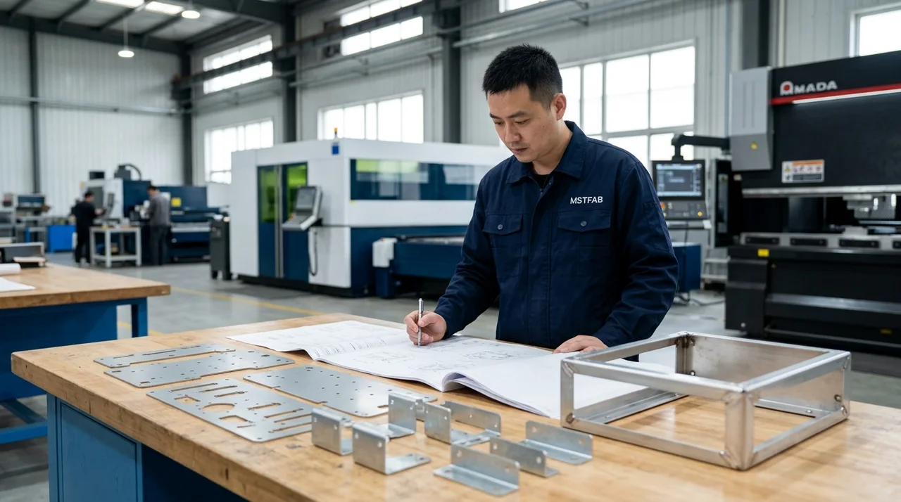
Figure 1: MSTFAB engineering team reviewing blueprint specifications alongside precision fiber laser-cut blanks, multi-bend brackets, and finished welded equipment sub-chassis.
2. High-Precision Fiber Laser Cutting: Optics, Assist Gases, and Kerf Dynamics
Fiber laser cutting has superseded traditional CO2 lasers and mechanical punching machines as the premier cutting technology for precision sheet metal. Operating at an optical wavelength of approximately 1.07 μm (one-tenth that of a CO2 laser’s 10.6 μm), fiber laser beams exhibit vastly superior absorption kinetics in highly reflective non-ferrous metals such as aluminum alloys (5052, 6061), brass, copper, and stainless steels.
Assist Gas Thermodynamics and Cut Edge Metallurgy
The selection of assist gas directly governs cut speed, edge squareness, and subsequent weldability:
- High-Pressure Nitrogen (N2) Cutting (18 – 25 bar): Nitrogen acts as an inert mechanical expulsion agent, blowing molten metal out of the kerf without chemical oxidation. The resulting cut edge is 100% oxide-free, presenting a clean metallic surface essential for direct TIG/laser welding and superior powder coating adhesion without secondary wire-brushing or acid pickling.
- Oxygen (O2) Assist Gas (0.5 – 5.0 bar): Oxygen initiates an exothermic iron oxidation reaction that releases supplementary thermal energy, enabling efficient cutting of heavy carbon steel plates (SPCC, Q235, A36 up to 20 mm). However, oxygen cutting leaves a thin, brittle iron-oxide slag layer on the cut face. For welded assemblies or powder-coated parts, this oxide layer must be removed via edge vibratory tumbling or shot blasting to prevent under-film paint peeling.
- High-Pressure Compressed Clean Dry Air (CDA) (12 – 16 bar): Blending approximately 78% nitrogen with 21% oxygen, compressed air offers an economical balance for medium-thickness steel and aluminum where slight edge discolouration is acceptable, reducing assist gas operational costs by up to 60%.
3. Automated Nesting, Grain Direction, and Common-Line Cutting (CLC)
Maximizing raw sheet utilization while preserving structural and bending performance requires intelligent automated nesting. MSTFAB utilizes state-of-the-art nesting engines (Lantek / SigmaNEST) integrated directly with our enterprise resource planning (ERP) system.
Sheet Rolling Grain Direction Constraints
During steel and aluminum coil rolling at the primary mill, metallic grains are elongated in the rolling direction. Bending sheet metal parallel to this grain orientation increases the risk of tensile cracking on the outer bend radius and magnifies angular springback variance by up to 40%. In our automated nesting rules:
- Grain Locking for Multi-Bend Parts: Parts featuring critical 90° bends are restricted from rotating freely on the nest. Nesting software locks the primary bend lines perpendicular (90°) or at 45° to the sheet rolling direction, ensuring uniform ductile deformation without micro-fractures.
- Common-Line Cutting (CLC): Where adjacent rectangular parts share identical straight edges, common-line cutting executes a single laser pass to part both components simultaneously. This slashes cutting cycle time by 25% and reduces thermal heat accumulation across the sheet skeleton.
- Skeleton Shredding and Fly-Cutting: Delicate perforated panels (such as EMI ventilation grilles with thousands of hexagonal apertures) are cut using fly-cutting algorithms, firing the laser on-the-fly without stopping at each hole contour, while automated skeleton shredding cuts the scrap lattice into manageable pieces for scrap extraction.
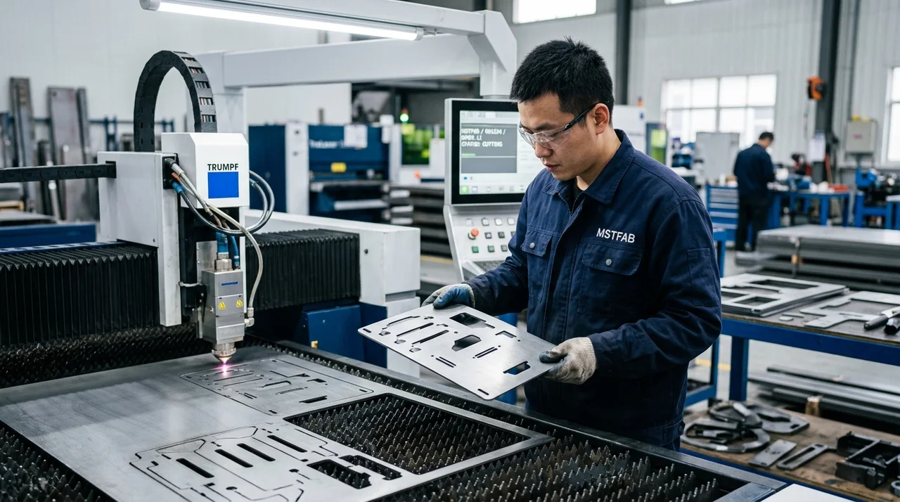
Figure 2: Laser cutting quality control: verifying kerf squareness, micro-tab retention, and hole diameter tolerances on flat sheet blanks prior to press brake forming.
4. CNC Press Brake Forming: Bending Physics, K-Factors, and Crowning Compensation
Forming flat sheet metal blanks into complex three-dimensional enclosures requires managing plastic strain, neutral axis shifting, and elastic springback. When sheet metal is bent over a V-die, the exterior face experiences severe tensile strain while the interior face experiences compressive stress.
Neutral Axis Derivation and Bend Deductions
The neutral axis represents the theoretical plane within the sheet thickness that undergoes zero change in length during forming. The mathematical position of this axis is defined by the K-factor (K = t / T), where t is the distance from the inside surface to the neutral line and T is sheet thickness. The flat blank development length requires calculating the exact Bend Allowance (BA) and Bend Deduction (BD):
BA = π × (θ / 180) × (R + K × T)
BD = 2 × (R + T) × tan(θ / 2) – BA
Where θ is the bend angle in degrees and R is the inside bend radius. In MSTFAB’s engineering database, K-factors are empirically verified through bend coupon testing rather than generic textbook tables: K ≈ 0.38 for 304 stainless steel, K ≈ 0.42 for SPCC mild steel, and K ≈ 0.44 for 5052-H32 aluminum under standard air-bending tooling configurations.
Eliminating Angular Springback and Canoe Bowing
Air-bending springback (Δθ) is governed by material yield strength (σ_y), elastic modulus (E), and bend radius (R):
Δθ ∝ (σ_y / E) × (R / T)
To eliminate angular variance and preserve ± 0.25° precision across high-volume production batches, MSTFAB’s CNC press brakes deploy:
- Real-Time Laser Angle Measurement: Twin optical laser sensors track the outer flange angle continuously during the bending stroke, transmitting real-time angle feedback to the CNC controller to adjust punch penetration depth dynamically.
- Active Dynamic Hydraulic Crowning: Multi-cylinder crowning beds automatically calculate and apply compensatory upward deflection along the lower bed, canceling out machine ram deflection under high bending tonnage. This guarantees identical 90° bend angles across the full 3-meter length of a panel without center bow or canoe deformation.
- Hardened Precision-Ground Tooling: Premium Wila/Trumpf-style precision tooling ground to ± 0.01 mm ensures exact alignment and zero tool deflection during multi-stage progressive bending operations.
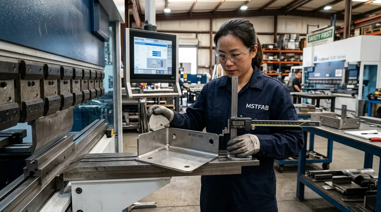
Figure 3: Metrology inspection of multi-bend brackets at the CNC press brake station, verifying flange heights and bend radii with digital height indicators on a surface table.
5. Precision Welding Engineering: TIG, Cold Metal Transfer (CMT), and Robotic Laser
Welding is the critical joining phase that transforms formed sheet metal components into a rigid structural assembly. However, the localized heat input of welding triggers metallurgical phase changes and thermal contraction stresses that can warp precision assemblies out of tolerance if not strictly controlled.
Welding Technologies for Sheet Metal Applications
- Pulsed TIG (GTAW) Welding: Utilizes a non-consumable tungsten electrode with an inverter-switched high/low current pulse frequency (50 to 200 Hz). The high-current pulse achieves rapid puddle penetration while the low-current background cycle allows the weld pool to freeze, reducing overall heat input by 40% compared to standard TIG. Ideal for aesthetic exterior corner seams, surgical stainless trays, and vacuum chambers (t = 0.8 – 2.5 mm).
- Cold Metal Transfer (CMT) Robotic MIG: A revolutionary gas metal arc welding variant where the wire electrode is mechanically retracted by a high-frequency servomotor at the exact instant of droplet short-circuit transfer. This controlled detachment delivers nearly zero spatter, exceptionally low thermal input, and the capability to join thin aluminum (t = 1.0 mm) and braze galvanized steel without burning away the protective zinc layer.
- Robotic Fiber Laser Welding: Represents the state of the art in high-speed, low-distortion joining. Fiber laser welding achieves an extreme power density with a depth-to-width aspect ratio exceeding 3:1. Heat-affected zones (HAZ) are compressed by over 80% relative to arc welding, producing narrow, cosmetically pristine weld beads with minimal thermal shrinkage stress.
- Resistance Spot Welding (MFDC Inverter): Deployed for high-speed structural bonding of overlapping sheet panels, internal stiffener hats, and card guide brackets. Medium Frequency Direct Current (MFDC, 1000 Hz) power sources ensure uniform energy delivery within milliseconds, eliminating weld indentation marks on cosmetic exterior surfaces.
6. Thermal Shrinkage and Residual Stress Management in Sheet Metal Welding
In thin sheet metal structures (t ≤ 2.0 mm), thermal distortion is the number one cause of scrapped weldments. When weld metal cools from its melting point (> 1400° C) to room temperature, longitudinal shrinkage tension creates compressive stresses in the adjacent parent sheet that trigger out-of-plane buckling (oil-canning).
The Mechanics of Longitudinal Shrinkage
The total longitudinal contraction force F_c generated by a cooling weld bead can be approximated by:
F_c = σ_y × A_w
Where σ_y is the yield strength of the deposited weld metal and A_w is the cross-sectional area of the fused weld bead. To keep F_c below the critical elastic buckling load of thin sheet panels, MSTFAB utilizes four proven engineering techniques:
- Laser Beam Wobble (Oscillation): In robotic laser welding, galvo mirrors oscillate the focused beam in circular or transverse sinusoidal patterns (frequency 100 to 500 Hz, amplitude 0.2 to 1.0 mm). Wobble welding widens the effective weld seam, allowing it to bridge joint fit-up gaps up to 0.40 mm without needing excess filler wire that would increase shrinkage mass.
- Symmetrical and Back-Step Welding Schedules: Weld passes are divided into short segments (50 to 80 mm) and deposited in back-step sequences. By depositing opposing seams symmetrically across the center of gravity, opposing thermal contraction vectors cancel out rather than accumulating into a net angular twist.
- Internal Heat Sinking with Copper Chill Bars: High-conductivity copper or aluminum backing plates clamped immediately beneath the weld seam rapidly conduct heat away from the heat-affected zone, narrowing the thermal gradient and preventing parent sheet softening.
- Pre-Cambering and Inverse Distortion: For long structural frames prone to bowing, components are pre-bent mechanically in the fixture in the reverse direction by an amount calculated via finite element analysis (FEA). As the weld cools, the thermal shrinkage pulls the assembly back into a perfectly straight, planar orientation.

Figure 4: Frame squareness verification: checking diagonal dimensions and perpendicularity of a TIG-welded structural chassis on a precision 3D modular welding fixture table.
7. Design for Manufacturability (DFM): Inter-Process Tolerance Budgets
The secret to high-yield sheet metal fabrication lies in understanding how tolerances cascade between laser cutting, press brake forming, and welding. Designing without factoring in machine kinematics creates impossible-to-manufacture features.
Critical DFM Rules for Sheet Metal Assemblies
- Hole-to-Bend Minimum Clearance: Placing a mounting hole inside the plastic deformation zone of a bend causes the hole to pull into an egg shape. To maintain hole roundness and true position tolerances, the minimum distance from the hole edge to the bend tangent line must satisfy:
Dmin ≥ 2.5 × T + R
- Minimum Flange Length for Tooling Clearance: To form a clean bend without the sheet edge falling into the V-die opening, the minimum allowable flange length Lmin must be at least:
Lmin ≥ (Vdie / 2) + 1.0 mm ≈ 4 × T
- Interlocking Tab-and-Slot Welded Construction: Instead of relying on manual operator positioning during welding, MSTFAB recommends incorporating laser-cut tab-and-slot locators. Self-fixturing tabs hold sheet metal components in precise planar alignment, reducing welding fixture setup time by 70% and ensuring frame diagonals are held within ± 0.50 mm.
- Corner Relief Notches: Where two orthogonal bends meet at an enclosure corner, relief notches must be laser-cut in the flat blank to eliminate tearing and corner bulging. Rectangular or teardrop relief notches with width ≥ T and depth extending beyond the bend tangent radius provide clean, flush corner seams ready for automated welding.
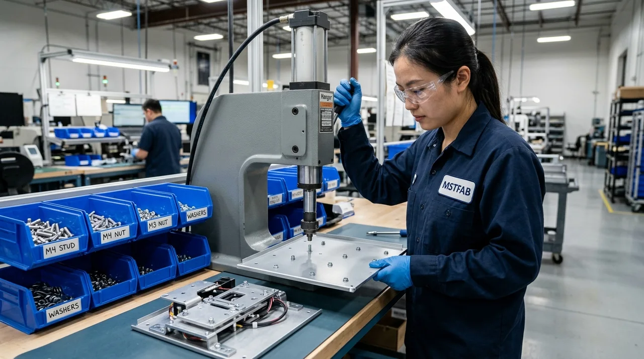
Figure 5: Secondary hardware installation: inserting self-clinching PEM nuts, studs, and standoffs on an automated force-monitored hydraulic press with optical part detection.
8. Secondary Value-Add: Haeger Clinching, Deburring, and Surface Finishing
Beyond the core operations of cutting, bending, and welding, modern OEM sheet metal enclosures require a suite of integrated secondary processes to be fully assembly-ready:
Automated Fastener Insertion (PEM Clinching)
Self-clinching threaded fasteners eliminate the need for loose nuts, tapped threads in thin sheet, or weld studs. MSTFAB operates high-speed Haeger hydraulic insertion presses equipped with automated bowl feeders and programmable force-displacement monitoring:
- Quality Control Squeeze Profile: Insertion force is strictly controlled within ± 5% of PennEngineering specification sheets. If a hole is missing, oversized, or double-fed, the press automatically locks out to prevent defective subassemblies.
- Flush Head Installation: External cosmetic panels utilize flush-head clinch studs (PEM FHS/FH) where the fastener head is embedded flush into the sheet surface and blended prior to powder coating, leaving completely clean exterior lines.
Automated Deburring and Edge Rounding
Even with nitrogen laser cutting, sharp 90° cut edges represent a safety hazard for technicians and cause premature paint failure (surface tension pulls liquid coatings away from sharp knife edges). MSTFAB processes flat blanks through automated wide-belt deburring and multi-disc edge-rounding machines (Timesavers), creating a consistent 0.2 mm to 0.5 mm radius corner break across all internal cutouts and exterior contours.
Surface Finishing and Environmental Protection
- Electrostatic Powder Coating: Automated 6-stage zirconium or iron phosphate pre-treatment followed by robotic powder spray and curing ovens, producing durable 60 to 90 μm finishes compliant with ASTM B117 salt spray ratings up to 1,000 hours.
- Anodizing (MIL-A-8625 Type II & III): Clear, black, or custom color sulfuric and hardcoat anodizing for aluminum parts, delivering superior surface hardness (up to 65 HRC) and corrosion immunity.
- E-Coating (Electrophoretic Deposition): Cathodic epoxy e-coat providing 100% complete coverage inside complex cavities, tubular frames, and welded sub-chassis with ultra-uniform film thickness (15 – 25 μm).
- Electro-Galvanizing and Zinc Plating (ASTM B633): Clear, yellow, or black trivalent passivated zinc coatings for internal computer chassis and brackets.
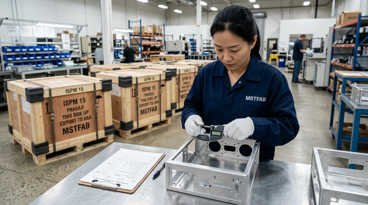
Figure 6: Final quality assurance and export logistics: completing comprehensive First Article Inspection (FAI) reports beside ISPM-15 heat-treated export crates with custom foam nesting.
9. Quality Assurance: CMM Verification, Weld Macro-Etching, and FAI Documentation
MSTFAB’s metrology lab ensures that fabricated sheet metal subassemblies strictly satisfy drawing specifications before leaving our facility:
- Bridge Coordinate Measuring Machine (CMM): Climate-controlled (20° C ± 1° C) touch-probe CMM inspection validates complex hole patterns, true position callouts, and multi-plane datums to ± 0.005 mm resolution.
- 3D Optical Blue-Light Scanning (Zeiss / GOM ATOS): Scans entire curved enclosures, generating color-coded 3D CAD deviation heatmaps that capture surface flatness, warpage, and twist across compound contours.
- Weld Macro-Etch Cross-Sectioning: Structural and pressure-tight welds undergo periodic destructive sectioning, polishing, and chemical etching per AWS D1.1 / AWS D9.1 standards to verify full weld throat penetration, sidewall fusion, and absence of porosity or micro-cracks.
- Full FAI Documentation (AS9102 / PPAP Level 3): Every production project includes complete balloon drawings, dimensional inspection data sheets, raw material mill test certificates (EN 10204 Type 3.1), and finishing compliance certificates.
10. Comprehensive Engineering Data Matrices and Performance Benchmarks
Table 1: Sheet Metal Fabrication Triad Performance Matrix
| Fabrication Process | Primary Machinery | Standard Tolerance | Precision Tolerance | Process Capability (Cpk) | Key Quality Metric |
|---|---|---|---|---|---|
| Fiber Laser Cutting | CNC Linear Drive Laser (6 kW – 15 kW) | ± 0.10 mm | ± 0.03 mm | 1.85 – 2.10 | Kerf perpendicularity & oxide-free cut edge |
| CNC Press Brake Bending | Dynamic Crowning + Laser Angle Sensors | ± 0.35 mm / ± 1.0° | ± 0.12 mm / ± 0.25° | 1.68 – 1.85 | Flange height & angle springback consistency |
| Robotic Fiber Laser Welding | 6-Axis Articulated Robot + 3 kW Laser | ± 0.40 mm | ± 0.15 mm | 1.65 – 1.82 | Narrow HAZ & minimal thermal distortion |
| Pulsed TIG (GTAW) Welding | Digital Inverter + 3D Modular Table | ± 0.75 mm | ± 0.30 mm | 1.40 – 1.60 | Aesthetic bead contour & zero burn-through |
| Cold Metal Transfer (CMT) | Fronius CMT Robotic Cell | ± 0.50 mm | ± 0.20 mm | 1.58 – 1.75 | Zero spatter & low heat penetration |
| Hardware Clinching (PEM) | Haeger 824 OneTouch Squeeze Press | ± 0.20 mm | ± 0.08 mm | 1.75 – 1.95 | Push-out force & torque-out resistance |
Table 2: Material Selection & Process Compatibility Matrix
| Material Specification | Fiber Laser Cutting Suitability | Press Brake Bending Characteristics | Welding Compatibility | Primary Industry Applications |
|---|---|---|---|---|
| 5052-H32 Aluminum | Excellent (N2 gas); clean, burr-free edge | Outstanding formability; R_min = 1.0 × T without cracking | Excellent with 4043/5356 filler (TIG / Laser) | Medical enclosures, avionics, electronics chassis |
| 6061-T6 Aluminum | Excellent (N2 gas); high precision cut | Moderate formability; requires R_min ≥ 2.5 × T to avoid cracking | Good; requires preheat/filler; loss of temper in HAZ | Machined structural bulkheads, rigid baseplates |
| AISI 304 / 304L Stainless | Superior with high-pressure N2 (oxide-free) | Higher springback; requires tonnage × 1.5 vs mild steel | Outstanding TIG, Laser, and CMT weldability | Food processing, pharmaceutical, industrial enclosures |
| AISI 316 / 316L Stainless | Superior with high-pressure N2 | High work hardening; requires dedicated K-factor libraries | Superior; low carbon prevents sensitization | Marine, clinical fluidics, chemical processing tanks |
| SPCC / Cold Rolled Steel | Fastest cut speeds; N2 or O2 assist | Predictable ductile bending; tight radii achievable | Universal weldability across TIG, MIG, Spot, Laser | Server racks, electrical control boxes, machinery guards |
| SECC Electro-Galvanized | Clean N2 cutting; zinc edge vaporization | Excellent formability without zinc coating spalling | Spot welding & CMT brazing preferred to preserve zinc | Internal computer sub-chassis, consumer electronics |
11. Real-World OEM Case Studies and Validated Performance Metrics
Case Study 1: Cleanroom Diagnostic Ultrasound System Console
OEM Challenge: A European medical device manufacturer was experiencing excessive field failure rates and visual panel gaps on an ultrasound cart enclosure. Three separate suppliers fabricated the laser parts, bent the brackets, and welded the frame, resulting in cumulative tolerance stack-up of ± 2.4 mm across adjoining exterior panels.
MSTFAB Solution:
- Consolidated the entire manufacturing process in-house under our ISO 13485 quality system.
- Redesigned the internal sub-chassis utilizing laser-cut tab-and-slot interlocking features, self-fixturing the frame prior to welding.
- Deployed robotic fiber laser welding, reducing total heat input by 75% compared to manual TIG and holding diagonal frame squareness within 0.40 mm.
- Formed exterior 5052-H32 aluminum cosmetic covers on CNC press brakes with laser angle measurement and protective polyurethane die films.
Quantifiable Outcome: Assembly fit-up time on the customer’s cleanroom assembly line plummeted by 42 minutes per console. Panel reveal gaps achieved ± 0.20 mm uniformity, and the defect reject rate dropped from 7.4% to 0.00% across 5,000 units shipped.
Case Study 2: Industrial 150 kW Solar Power Inverter Enclosure (IP66 Sealed)
OEM Challenge: A clean energy equipment manufacturer required a robust 2.0 mm 304 stainless steel outdoor inverter housing capable of passing IP66 dust/water ingress tests. Weld distortion on door sealing flanges was causing silicone gaskets to lose sealing pressure at corner joints.
MSTFAB Solution:
- Transitioned corner welding from manual MIG to Cold Metal Transfer (CMT) robotic welding, eliminating weld spatter and minimizing flange warpage.
- Programmed press brake dynamic crowning to achieve zero center-bow along the 1.4-meter gasket sealing channel.
- Conducted automated helium leak testing and coordinate measuring machine (CMM) verification on 100% of First Article production units.
Quantifiable Outcome: Successfully achieved certified IP66 and NEMA 4X compliance on the first test cycle at TÜV SÜD. Gasket compression remained perfectly uniform at 35% ± 3% across the entire perimeter, with zero leaks detected under high-pressure water jet impingement.
12. Frequently Asked Technical Questions (32 Detailed Engineering Q&As)
Q1: What are the primary advantages of consolidating laser cutting, bending, and welding under one supplier?
Consolidating these three core operations eliminates inter-process tolerance stack-up and vendor finger-pointing. The fabricator takes end-to-end accountability: compensating flat blank laser kerf for actual press brake springback, and matching formed bend angles to automated welding fixture tolerances.
Q2: What positioning accuracy can MSTFAB maintain on fiber laser cut blanks?
Our CNC fiber laser cutting centers achieve linear positioning accuracy of ± 0.02 mm and repeatability of ± 0.01 mm, maintaining hole diameter and perimeter tolerances within ± 0.03 mm on sheet metal up to 6.0 mm thick.
Q3: Why is high-pressure nitrogen assist gas mandatory for laser cutting stainless steel and aluminum?
Nitrogen is an inert gas that purges molten metal without chemical oxidation. It leaves a 100% oxide-free metallic cut edge that is immediately ready for robotic welding and powder coating without secondary grinding or chemical deoxidation.
Q4: How does MSTFAB prevent angular springback during press brake bending?
We deploy press brakes equipped with real-time optical laser angle measurement sensors. The sensors monitor flange angle deflection during punch descent, dynamically adjusting bottom dead center depth to compensate for material yield strength and coil grain variation in real time.
Q5: What is CNC dynamic hydraulic crowning and why is it necessary?
Under heavy bending tonnage, the press brake ram and bed deflect in opposing directions, causing workpieces to bend narrower at the ends and open wider at the center. Dynamic hydraulic crowning applies real-time upward hydraulic pressure along the lower bed, canceling deflection and guaranteeing uniform angles across 3-meter parts.
Q6: How does robotic fiber laser welding compare to conventional TIG welding for sheet metal?
Fiber laser welding delivers over 10 times higher power density with an aspect ratio exceeding 3:1. It reduces heat input by 70% to 80%, narrows the heat-affected zone, dramatically limits thermal distortion, and welds at speeds 3 to 5 times faster than manual TIG.
Q7: What is Cold Metal Transfer (CMT) welding and where is it used?
CMT is a robotic MIG welding variant where the wire is retracted mechanically at the instant of droplet short-circuit. It provides spatter-free, ultra-low heat input joining, ideal for thin aluminum (t ≤ 1.2 mm) and joining galvanized steel without vaporizing the protective zinc layer.
Q8: What is the minimum recommended hole-to-bend distance in sheet metal design?
To prevent the hole from distorting into an oval shape during bending, the minimum clearance from the hole edge to the bend line tangent must be Dmin ≥ 2.5 × T + R, where T is sheet thickness and R is inside bend radius.
Q9: How do tab-and-slot features improve welded frame accuracy?
Laser-cut tabs and interlocking slots mechanically align sheet metal parts into a rigid, self-locating subassembly before welding. This eliminates operator fixturing errors, locks in 90° squareness, and maintains diagonal symmetry within ± 0.50 mm.
Q10: What is the minimum bend radius achievable on 5052-H32 aluminum without cracking?
5052-H32 aluminum can be bent to an inside radius equal to material thickness (R ≈ 1.0 × T) perpendicular to the rolling grain without orange-peel cracking. Parallel to grain, R ≥ 1.5 × T is recommended.
Q11: How do you verify push-out and torque-out resistance on self-clinching PEM fasteners?
We perform destructive and non-destructive SPC sampling using digital force gauges and torque wrenches. PEM nuts installed on our Haeger presses must strictly satisfy PennEngineering mechanical retention minimums.
Q12: What edge treatment is performed after laser cutting to prepare parts for powder coating?
All cut blanks pass through automated dual-sided deburring and edge-rounding machines with oscillating abrasive blocks, generating a consistent 0.2 to 0.5 mm radius corner break to eliminate sharp edges where paint would otherwise pull thin.
Q13: How do you prevent weld heat tint and restore corrosion resistance on stainless steel?
We execute citric acid chemical passivation per ASTM A967 (Citric 4). Passivation removes free iron, chromium-depleted heat tint zones, and weld scale, restoring an unbroken chromium-oxide passive film with Cr/Fe ≥ 1.8.
Q14: What is the maximum sheet size and thickness MSTFAB can process?
Our fiber lasers accommodate sheets up to 3000 mm × 1500 mm (10 ft × 5 ft). Thickness capacity: stainless steel up to 16 mm, aluminum up to 12 mm, carbon steel up to 25 mm. CNC press brakes provide 3100 mm bending length and 170-ton capacity.
Q15: How do you ensure electrical grounding continuity on powder-coated enclosures?
Ground studs and grounding bosses are masked using high-temperature silicone caps and polyimide tape prior to powder spraying. Post-cure electrical resistance is verified ≤ 0.1 Ω under 25 A test current per IEC 60601-1 and UL 508A standards.
Q16: What documentation is provided with an initial production run?
We provide a comprehensive First Article Inspection (FAI) package per AS9102 / ISO 9001 format, including ballooned drawings, 100% dimensional inspection reports, raw material mill test certificates (EN 10204 3.1), and coating compliance logs.
Q17: What quality management certifications does MSTFAB hold?
MSTFAB operates under ISO 9001:2015 and ISO 13485:2016 certified quality systems, ensuring complete process control, equipment qualification (IQ/OQ/PQ), and unbroken material lot traceability.
Q18: How do you prevent surface scratches during press brake bending on cosmetic panels?
We apply high-density protective polyurethane films to the sheet surface and utilize non-marking urethane bottom die inserts to eliminate metal-on-metal friction scuffing during forming.
Q19: What is the typical lead time for custom sheet metal prototypes vs production runs?
Laser-cut and formed prototypes are completed in 5 to 7 working days. Full production runs with FAI packages, hardware insertion, and powder coating ship within 3 to 4 weeks.
Q20: Can you weld dissimilar metals, such as aluminum to stainless steel?
Direct fusion welding of aluminum to stainless steel causes brittle intermetallic compound formation. We utilize mechanical clinching, structural epoxy bonding, or specialized bimetallic transition inserts for dissimilar metal assemblies.
Q21: How do you maintain diagonal squareness on large welded sheet metal enclosures?
We utilize precision 3D modular welding tables with ground datum stops and pneumatic toggle clamps, combined with symmetrical staggered welding sequences and laser-cut interlocking tabs to hold diagonal difference ≤ 0.8 mm across a 1500 mm frame.
Q22: What welding codes and standards are your welders certified to?
Our welding operators and robotic programs are certified to AWS D1.1 (Structural Steel), AWS D1.2 (Structural Aluminum), AWS D1.3 (Sheet Steel), and AWS D9.1 (Sheet Metal Welding Code), with annual re-qualification logs.
Q23: How do you prevent thread fouling during powder coating?
All internal threaded holes and PEM clinch standoffs are plugged with tapered high-temperature silicone plugs prior to painting, followed by 100% Go / No-Go thread plug gauge auditing after curing.
Q24: What is the difference between air bending, bottom bending, and coining?
Air bending contacts the sheet at three points (punch tip and die shoulders), offering maximum angle versatility with minimum tonnage. Bottoming presses the sheet into full die contact with 3 to 5 times more tonnage. Coining penetrates the neutral axis with 8 to 10 times more tonnage, permanently eliminating springback but accelerating tool wear.
Q25: Can MSTFAB perform sub-assembly and electro-mechanical integration?
Yes. Beyond raw fabrication, we provide turnkey box-build services: installing hinges, locks, gas struts, cooling fans, wire harnesses, optical windows, and EMI shielding gaskets in an ESD-controlled assembly cell.
Q26: What powder coating thickness and adhesion standards do you maintain?
We adhere to ASTM B499 (magnetic/eddy current film thickness: 60 – 90 μm) and ASTM D3359 Method B (cross-hatch tape adhesion: Class 5B with 0% lattice flaking).
Q27: How do you handle rapid engineering change orders (ECO) during ongoing production?
Under our ISO-certified change control procedure, incoming ECOs trigger immediate ERP revision locks, quarantining of legacy cutting programs, physical labeling of work-in-progress, and updated FAI sign-off before manufacturing the new revision.
Q28: What is optical 3D scanning and how is it used in your metrology lab?
Our Zeiss/GOM optical blue-light scanner captures millions of 3D surface coordinates, comparing physical formed enclosures against 3D CAD step models to generate color deviation heatmaps that immediately reveal surface flatness and twist.
Q29: What are corner relief notches and why are they critical on laser-cut blanks?
When two 90° bends intersect at an enclosure corner, relief notches prevent material from bunching, tearing, or bulging, enabling clean, flush corner seams that can be seamlessly welded and ground smooth.
Q30: How do you package sheet metal assemblies for intercontinental ocean export?
Parts are masked with protective PE film, packed in custom CNC-routed polyethylene foam cells inside heavy-gauge vapor barrier bags with activated silica gel desiccant, and secured in ISPM-15 certified heat-treated wooden crates.
Q31: Can MSTFAB assist in redrafting 2D prints into parametric 3D CAD models?
Yes. Our engineering department can convert legacy 2D drawings, paper prints, or physical sample parts into fully parametric 3D CAD models (STEP, SolidWorks) complete with calibrated K-factors and optimized DFM features.
Q32: How can an OEM request a technical DFM review and quotation?
Submit your 3D CAD files (STEP, IGES, SolidWorks) and 2D PDF prints with critical tolerance callouts via our secure portal. Our engineering team returns a comprehensive DFM feedback report and firm price quotation within 24 to 48 hours.
Streamline Your Sheet Metal Sourcing with MSTFAB’s Integrated Triad
Eliminate multi-vendor coordination headaches, tolerance stack-up errors, and assembly line delays. Partner with MSTFAB for precision fiber laser cutting, CNC press brake forming, robotic welding, and automated hardware insertion backed by ISO 9001 and ISO 13485 quality systems. Contact our engineering team today for a comprehensive DFM review and quotation.
 WeChat Contact
 WhatsApp Me Directly