⚙ Quick Engineering Reference: Cable Clamp & Strain Relief Rules
Under UL 508A Clause 29, NEC Article 314.17, and IEC 62444, industrial junction box cable entries must provide positive mechanical strain relief capable of withstanding dynamic pull-out forces (Fpull = 10 · Dcable + 75 Newtons) so that external mechanical tension is never transmitted to electrical terminal blocks or internal wire splices. For NEMA 4X / IP66 washdown enclosures, cable clamps must be integrated into bottom-entry removable gland plates or certified compression cord grips with elastomeric grommets, maintaining a minimum 12 mm wrench clearance envelope between adjacent gland hexagonal nuts.
In industrial automation, material handling robotics, solar combiners, and process control machinery, electrical junction boxes serve as the critical nexus where field power, sensor, and industrial Ethernet cables converge. While electrical engineers focus on terminal wire sizing and circuit protection, the physical interface where cables penetrate the metal enclosure—the cable clamp, strain relief bracket, and gland plate—is the primary mechanical barrier preventing environmental failure, conductor pull-out, and insulation abrasion.
Poor Design for Manufacturability (DFM) in cable entry zones generates severe production bottlenecks and warranty claims: overcrowded hole patterns that prevent electricians from tightening gland locknuts, sharp laser burrs that slice through cable jackets, high-pressure washdown leaks through improperly compressed rubber seals, and structural panel oil-canning caused by heavy unsupported vertical cable bundles.
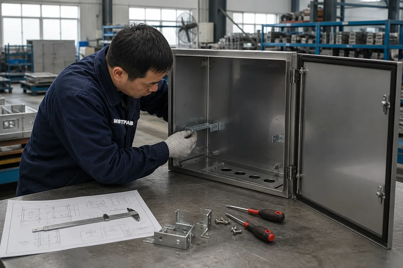
Figure 1: Heavy-duty NEMA 4X industrial automation junction box featuring bottom-entry cable gland plates and internal C-rail strain relief clamping bars engineered by MSTFAB.
1. Regulatory Architecture: UL 508A, NEC 300.19, NEC 314.17 & IEC 62444 Mandates
Cable entry engineering is not merely a matter of mechanical convenience; it is governed by strict, legally enforceable North American and international safety directives:
1.1 UL 508A Clause 29: Strain Relief Mechanics
Under UL 508A (Industrial Control Panels), all factory-wired and field-installed conductors entering an enclosure must have mechanical strain relief provided at or adjacent to the entry point. The fundamental test requires applying a sustained direct axial pull force (typically 156 Newtons / 35 lbf for 1 minute) along the cable axis. During this test:
- There must be zero axial movement of the conductors at internal terminal block screw connections.
- The outer cable sheath must not slip through the clamping jaws or grommet by more than 2.0 mm.
- The cable entry fitting must not loosen, rotate, or deform the sheet metal enclosure wall.
1.2 IEC 62444 Retention & Cable Anchorage Classification
International standard IEC 62444 (Cable Glands for Electrical Installations) establishes mathematical criteria for cable pull-out retention force (Fpull) based on cable diameter (D):
| Standard & Code | Subject Requirement | Engineering Mandate | DFM Failure Risk if Ignored |
|---|---|---|---|
| UL 508A Clause 29.3 | Mechanical Strain Relief | 35 lbf (156 N) pull force test without terminal displacement | Wires pulled out of terminals; electrical arcing and field inspection rejection |
| NEC 300.19(A) | Vertical Cable Weight Support | Cables in vertical raceways must be clamped at specified intervals | Cable deadweight pulls terminal studs downward, cracking backpans |
| NEC 314.17(B) | Conductor Abrasion Protection | Insulating bushings or smoothly radiused edges (R ≥ 1.5 mm) | Vibration chafes insulation against laser burrs, causing dead shorts |
| NEC 300.20(B) | Eddy Currents in Ferrous Walls | All phase conductors must pass through the same opening or non-ferrous plate | Magnetic hysteresis overheats steel enclosure wall above150^circC |
2. Architectural Topologies: Individual Glands, Internal C-Rails & Modular Frames
Industrial control systems deploy three primary cable entry and clamping topologies. Selecting the optimal configuration depends on cable volume, pre-terminated connector geometries, and washdown severity:
| Clamping Topology | Ingress Protection Rating | Pre-Terminated Connector Support | Cable Density (per100 cm^2) | Primary Application Scope |
|---|---|---|---|---|
| Individual Metallic Cord Grips | NEMA 4X / IP68 (Submersible) | None (Raw cable ends only) | Low (4 – 8 cables) | Heavy power feeds, offshore marine, chemical skids |
| Modular Multi-Cable Entry Frames | NEMA 4X / IP66 (Hose-down) | Outstanding (Pre-wired RJ45, M12) | High (16 – 32 cables) | Robotics, machine vision, PLC automation I/O |
| Internal C-Rail Strain Relief Bars | Secondary internal support | Compatible with all cables | Very High (Continuous rail) | High-vibration machinery, vertical riser relief |
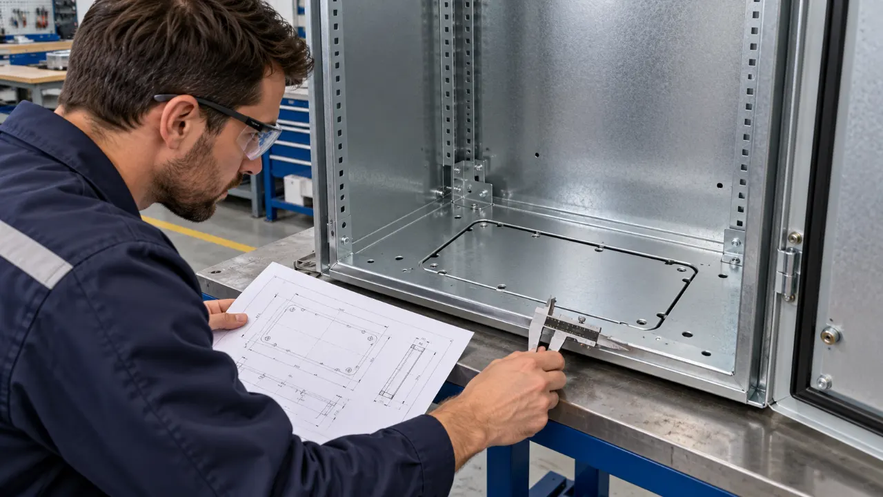
Figure 2: Staggered honeycomb cable entry layout on a removable aluminum gland plate, optimizing hole density while maintaining full360^circwrench swing envelopes.
3. Wrench Clearance & Tool Envelope Engineering: Eliminating Installation Clashes
The most notorious manufacturing error in electrical junction box DFM is cable gland overcrowding. Mechanical engineers frequently place laser-cut holes based solely on gland outer diameters, completely neglecting the physical envelope required for the assembly wrench or socket tool. When the box arrives at the electrical panel shop, the technician cannot tighten the locknuts on the inside or turn the hex body on the outside.
3.1 Tool Envelope Formulation
To ensure complete360^circwrench tightening access without damaging adjacent fittings, the center-to-center hole pitch (Phole) must satisfy:
| Thread Size (Metric / NPT) | Hole Cutout Diameter | Gland Hex Across Flats | Min. Center PitchPmin | Min. Distance to Box Wall |
|---|---|---|---|---|
| M16 × 1.5 / 3/8" NPT | 16.3 mm(0.642 in) | 22.0 mm(0.866 in) | 36.0 mm(1.417 in) | 24.0 mm(0.945 in) |
| M20 × 1.5 / 1/2" NPT | 20.4 mm(0.803 in) | 27.0 mm(1.063 in) | 42.0 mm(1.654 in) | 28.0 mm(1.102 in) |
| M25 × 1.5 / 3/4" NPT | 25.4 mm(1.000 in) | 33.0 mm(1.299 in) | 50.0 mm(1.968 in) | 32.0 mm(1.260 in) |
| M32 × 1.5 / 1" NPT | 32.5 mm(1.280 in) | 42.0 mm(1.654 in) | 62.0 mm(2.441 in) | 38.0 mm(1.496 in) |
| M40 × 1.5 / 1-1/4" NPT | 40.5 mm(1.594 in) | 52.0 mm(2.047 in) | 74.0 mm(2.913 in) | 45.0 mm(1.772 in) |
The Honeycomb Layout Strategy: When high cable density is required in compact junction boxes, MSTFAB staggers alternate rows of holes at a60^circtriangular pitch rather than a square grid. This honeycombed layout increases effective cable density by up to 28% while preserving full open wrench swing access for each individual gland.
4. Removable Gland Plates vs. Direct Enclosure Machining DFM
When designing cable entries, engineers must choose between punching/machining holes directly into the welded enclosure body or integrating a removable bolted gland plate.
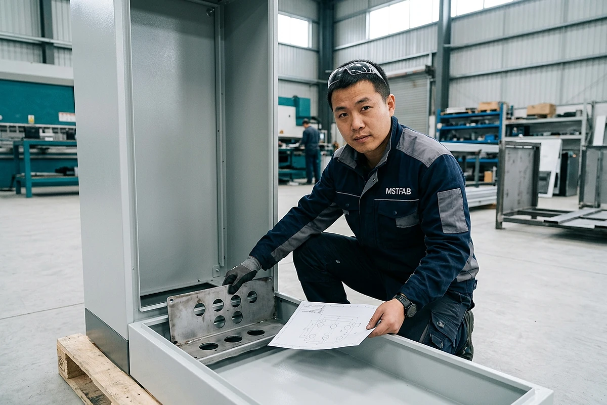
Figure 3: Removable 316L stainless steel gland plate with CNC laser-pierced entry ports and continuous robotic FIPFG polyurethane perimeter sealing gasket at MSTFAB.
4.1 Why Removable Gland Plates Are the Superior DFM Architecture
- Field Customization Without Metal Shavings: In field installations, drilling conduit holes directly into a fully assembled electrical control cabinet generates sharp metallic chips and cutting oil that fall into live PLCs and circuit breakers. A removable gland plate can be detached and punched on a workbench using standard Greenlee hydraulic knockout punches, ensuring zero contamination inside the cabinet.
- Rapid Re-Tooling for Field ECOs: When project engineering changes require new sensor cables, replacing an inexpensive flat gland plate takes 10 minutes, whereas modifying a welded enclosure shell requires replacing the entire cabinet.
- Material Decoupling for Eddy-Current Prevention: A removable plate allows engineers to specify a non-magnetic aluminum (5052-H32) or 316 stainless plate on an economical painted carbon steel enclosure, completely eliminating electromagnetic induction hazards at minimal BOM cost.
4.2 Gland Plate Sealing & Fastener DFM
To maintain NEMA 4X / IP66 washdown integrity across the gland plate perimeter interface:
- Formed Knife-Edge Return Flange: The enclosure body cutout must incorporate an internal90^circformed return flange with a smooth 1.5 mmradiused edge that presses into the gland plate gasket.
- Continuous Seamless FIPFG Gasketing: MSTFAB dispenses a continuous closed-cell polyurethane or silicone foam gasket bead (6.0 mmwidth× 3.5 mmhe) directly into a CNC-formed gasket retaining groove on the gland plate, eliminating glued butt-joint leak paths.
- Fastener Pitch and Torque Uniformity: Fastener spacing (Lpitch) along the gland plate perimeter must not exceed 75 mm(3.0 in). Exceeding 100 mmspacing causes the plate to bow outward between screws under gasket rebound pressure, reducing seal compression below the critical30% threshold.
5. Electromagnetic Eddy-Current Induction & Slotting DFM per NEC 300.20
A dangerous electrical failure mode that is frequently overlooked by mechanical sheet metal designers is electromagnetic inductive heating caused by alternating current (AC) entering ferrous enclosures.
5.1 Magnetic Loop Physics
When a single-conductor AC cable carrying high current (I ≥ 50 Amperes) passes through an individual hole in a carbon steel enclosure wall, the alternating magnetic flux (Φ = μ · I / (2π r)) circulates through the magnetic steel ring surrounding the hole. This magnetic hysteresis and induced eddy currents generate intense localized resistive heating:
In solar inverters, motor control centers, and EV charging pedestals, unmitigated steel walls around single-conductor cables can EU REACH Regulation operating temperatures exceeding 160^circC(320^circF). This thermal runaway melts XLPE cable insulation, degrading dielectric resistance until catastrophic phase-to-enclosure flashovers occur.
5.2 MSTFAB Engineering Solutions per NEC 300.20(B)
- Non-Ferrous Gland Plates: MSTFAB standardizes on 5052-H32 Aluminum (3.0 mm) or 316L Austenitic Stainless Steel for high-power gland plates. Austenitic stainless steel has a relative magnetic permeability (mu_r ≈ 1.02) virtually identical to air, completely preventing magnetic flux concentration.
- Laser-Cut Induction Breaking Slots: If carbon steel walls must be used, MSTFAB CNC lasers cut a continuous3.0 mmwide air slot bridging between each individual phase hole (Phase A, B, C, and Neutral). This physical air gap breaks the magnetic loop, dropping eddy-current heating by over 95%. The slot is then sealed using a non-conductive, fire-rated silicone elastomer.
6. Internal C-Rail Strain Relief & Vertical Cable Support Mechanics
While external cable glands provide environmental ingress protection, relying entirely on the gland rubber grommet to support the mechanical weight of heavy multi-conductor cables violates best engineering practices. Over months of thermal cycling and machinery vibration, the rubber cold-flows (creeps), causing cables to slip downward and pulling terminal connections loose.

Figure 4: Interior view of industrial control cabinet showing galvanized C-rail strain relief bar positioned 100 mm below the bottom gland entry plate, supporting heavy copper conductors.
6.1 The Two-Tier Strain Relief Architecture
- Primary Environmental Seal (Tier 1): Cable gland or modular transit frame at the enclosure boundary provides IP66/NEMA 4X liquid and dust exclusion.
- Secondary Mechanical Anchor (Tier 2): A heavy-duty slotted C-profile rail (such as30 × 15 mmC-rail per DIN EN 60715) welded or bolted to the enclosure internal frame75 – 120 mmdirectly beneath the gland plate. Cables are secured to the C-rail using heavy-duty saddle clamps with plastic pressure troughs or stainless steel cable ties, absorbing 100% of cable hanging weight and external pulling tension.
NEC 300.19 Spacing for Vertical Conductor Supports:
- 18 AWG to 8 AWG: Maximum vertical span between supports =30 meters(100 ft).
- 6 AWG to 1/0 AWG: Maximum vertical span =15 meters(50 ft).
- 2/0 AWG to 4/0 AWG: Maximum vertical span =12 meters(40 ft).
- 250 kcmil to 350 kcmil: Maximum vertical span =10.5 meters(35 ft).
7. Failure Modes & Effects Analysis (FMEA) for Cable Clamp & Entry Systems
MSTFAB applies rigorous Process FMEA controls to prevent design, tooling, and manufacturing defects in electrical cable entry systems:
| Potential Failure Mode | Root Cause Mechanism | Severity × Occurrence × Detection | MSTFAB Poka-Yoke Prevention | Revised RPN |
|---|---|---|---|---|
| Water Leaks Past Gland Sealing Ring | Hole pitch too tight; technician cannot torque hex locknut with wrench | 9 × 5 × 5 = 225 | Automated 3D CAD design rule enforcing minimum 12 mm wrench clearance | 9 × 1 × 2 = 18 |
| Conductor Insulation Chafing | Microscopic burrs and dross on laser-pierced hole perimeter | 8 × 5 × 4 = 160 | Automated dual-sided rotary deburring machine creating0.5 mmedge radius | 8 × 1 × 2 = 16 |
| Magnetic Induction Overheating | Single-conductor AC cables passed through individual steel holes | 9 × 4 × 5 = 180 | Mandate 5052 aluminum or 316L stainless gland plates for currents> 50 A | 9 × 1 × 1 = 9 |
| Gland Plate Center Bowing / Leak | Fastener pitch> 100 mm; gasket rebound pressure arches thin plate | 8 × 4 × 4 = 128 | Thicker 12-gauge (2.7 mm) plate + maximum 65 mm fastener spacing | 8 × 1 × 2 = 16 |
| Terminal Block Pull-Out | Relying on gland grommet alone without internal C-rail strain relief | 7 × 5 × 4 = 140 | Standard internal slotted C-rail welded 100 mm below entry plate | 7 × 1 × 1 = 7 |
8. Industrial Case Study: AMR Fleet Fast-Charging Hub Junction Boxes (320 Units)
A high-growth robotics automation company operating autonomous mobile robot (AMR) material handling fleets in logistics distribution centers was plagued by severe electrical failures across 320 outdoor fast-charging power distribution skids:
Problem Definition & Field Failures
- Each charging hub distribution box received 36 high-flex power and communications cables entering through individual compression glands on a flat carbon steel bottom panel. Due to extreme hole overcrowding (6.0 mmedge clearance), assembly technicians could not use standard wrenches, resulting in over 40% of glands being finger-tight.
- During seasonal heavy rains, water pooled along sagging cable runs and entered through loose glands, shorting out480 Vhigh-frequency DC fast chargers.
- In addition, the 200A AC feeder cables passing through individual carbon steel punch-outs generated eddy-current heating that reached115^circC, melting cable insulation within 90 days.
MSTFAB DFM Engineering Solution
- Transition to Removable 5052-H32 Aluminum Gland Plate: Replaced the welded steel bottom with a3.0 mmmarine-grade aluminum plate, instantly eliminating 100% of electromagnetic eddy-current inductive heating.
- Staggered Honeycomb Hole Layout: Re-engineered the gland pattern into a60^circstaggered layout, providing an unobstructed14 mmwrench swing envelope around every single gland fitting.
- Continuous Robotic FIPFG Polyurethane Gasket: Integrated a robotically dispensed seamless foam gasket bead along the gland plate knife edge, achieving certified IP66 / NEMA 4X hose-down sealing.
- Internal Galvanized C-Rail Saddle Support: Welded dual slotted C-rails100 mmabove the gland plate, clamping each cable with elastomer-lined saddles to absorb100% of external dynamic cable whip and vibration.
Quantified Customer Results
9. 12-Point Engineering DFM Checklist for Cable Clamps & Gland Plates
Before releasing CAD drawings for enclosure cable entries, audit every parameter against this 12-point engineering checklist:
- Maintain Minimum12 mmClearance Between Gland Hex Flats: Accommodate standard open-end wrenches and socket tools without collision.
- Prioritize Bottom Cable Entry: Position cable entries on the bottom enclosure face whenever possible to prevent water accumulation along cable jackets.
- Specify Non-Magnetic Gland Plates for AC Currents> 50 A: Mandate 5052 aluminum or 316 stainless steel to eliminate eddy-current inductive heating per NEC 300.20.
- Enforce Maximum75 mmFastener Spacing on Gland Plates: Prevent plate bowing and gasket decompression between perimeter clamping screws.
- Incorporate Internal C-Rail Strain Relief: Position slotted C-rail75 – 120 mmbelow entries to absorb 100% of cable weight per NEC 300.19.
- Apply Dual-Sided Rotary Deburring: Enforce smooth edge radiusing (R ≥ 0.5 mm) on all punched holes to prevent cable jacket abrasion.
- Use Staggered Honeycomb Hole Layouts: Increase cable density by up to 28% compared to square grids while preserving full wrench swing.
- Design Formed Return Flanges on Enclosure Cutouts: Provide continuous knife-edge sealing contact against the gland plate gasket.
- Verify UL 508A Pull-Out Compliance: Ensure cable clamping mechanism withstands35 lbf(156 N) tensile pull without conductor slippage.
- Specify Robotically Dispensed FIPFG Gaskets: Eliminate glued gasket corner splices that fail under high-pressure washdown testing.
- Maintain Minimum25 mmOffset from Enclosure Walls: Allow torque wrenches to seat cleanly over locknuts on the enclosure interior.
- Audit Hole Pitch with CMM First Article Inspection: Verify hole pitch tolerances within± 0.15 mmbefore volume stamping.
10. Structural FEA: Gland Plate Deflection & Gasket Pre-Load Distribution
A removable gland plate bolted around its perimeter behaves mechanically as a continuous beam on elastic foundation subjected to discrete point loads (the clamping screws) and distributed upward reaction pressure (the compressed elastomeric gasket).
10.1 Inter-Bolt Span Deflection Formulation
Between any two adjacent clamping bolts separated by span lengthLbolt, the plate bows outward under gasket rebound force (wgasket = Pseal · Wgasket). The maximum mid-span deflection (deltamid) is governed by beam bending theory:
Because deflection is inversely proportional to the cube of thickness (t^3), increasing gland plate thickness from 16-gauge (1.5 mm) to 12-gauge (2.7 mm) reduces mid-span bowing by 82.6%. This ensures that gasket compression remains uniformly above30% across the entire perimeter, guaranteeing hermetic sealing against65 GPMhose-down sprays.
11. High-Density Modular Multi-Cable Transit (MCT) Frame Integration DFM
In modern Industry 4.0 automation, machine tools frequently connect 40 to 100 pre-terminated sensor and servomotor cables fitted with bulky RJ45, USB, HDMI, M12, or Harting connectors. Traditional cord grips require cutting and re-soldering the connector pins in the field, voiding factory sensor warranties and introducing wiring faults.
11.1 DFM Rules for Split Multi-Cable Entry Frames
- Standard Rectangular Cutout Dimensions: Split frames (such as Icotek KEL-U, Roxtec CF 16, or Murrplastik KDL) utilize standard 24-pin industrial connector cutouts (36 × 112 mm) or 16-pin cutouts (36 × 86 mm). MSTFAB holds laser cutout profile tolerances strictly to± 0.15 mmto ensure perfect frame seating.
- Pre-Formed Standoff Clinch Studs: To eliminate loose nuts that can drop into live electronics during field servicing, MSTFAB presses flush-head stainless steel clinch studs (PEM studs) into the enclosure cutout perimeter, allowing rapid one-sided screw fastening.
- Integrated Cable Tie Strain Relief Combing: The split frame incorporates an integral bottom comb plate. Nylon zip-ties clamp each individual cable directly to the frame teeth, achieving certified strain relief per EN 62444 Type B without auxiliary mounting brackets.
12. Electromagnetic Compatibility (EMC/EMI): 360-Degree Shield Grounding Clamps
In automated industrial control machinery driven by Variable Frequency Drives (VFDs) and high-speed brushless servomotors, switching transient pulse-width modulation (dV/dt > 10 kV/μ s) induces massive high-frequency common-mode noise along power and feedback cables. If shielded cables are grounded using conventional twisted “pigtail” drain wires:
A simple50 mmtwisted ground wire introduces over 31 Omegaof high-frequency impedance at 100 MHz, completely destroying the cable shield’s ability to divert RF noise to ground and radiating EMI throughout the control cabinet.
- 360-Degree Spring-Loaded EMC Saddle Clamps: MSTFAB integrates un-painted, zinc-plated or stainless steel C-profile grounding busbars positioned60 mmbeneath the gland plate. Spring-loaded shielding clamps (such as Icotek SKL or Phoenix Contact SK series) press the exposed braided cable shield against the conductive rail with continuous large-area contact (Zground < 0.05 ω), achieving> 65 dBattenuation across10 kHzto 1 GHz.
- Conductive Grounding Landings on Powder-Coated Plates: MSTFAB applies precision silicone masking dots over grounding stud contact lands prior to powder coating, ensuring direct metal-to-metal bonding between the gland plate and chassis ground strap.
13. Chemical Resistance & Washdown Elastomer Aging for Cable Gland Grommets
A cable entry’s environmental seal is governed by the elastomeric compression sleeve (grommet) clamped around the outer jacket. In harsh chemical processing, agricultural washdowns, and food beverage sanitation, aggressive cleaning reagents can rapidly degrade rubber sealing elements:
| Grommet Elastomer | Chlorinated Alkaline Foam | Peracetic Acid Sanitizer | Hydrocarbon Oils & Coolants | Temperature Operating Limits |
|---|---|---|---|---|
| Nitrile Butadiene (NBR) | Poor (Hardens and cracks) | Rapid chemical attack | Outstanding (Oil resistant) | -40^circCto+100^circC |
| EPDM Synthetic Rubber | Outstanding resistance | Excellent compatibility | Poor (Swells in petroleum oils) | -40^circCto+130^circC |
| Fluoroelastomer (FKM / Viton) | Exceptional | Exceptional | Exceptional | -20^circCto+200^circC |
| Platinum Silicone Elastomer | Very Good (Steam sterilizable) | Very Good | Fair (Avoid solvent immersion) | -60^circCto+230^circC |
By matching grommet polymer chemistry to specific plant sanitizing chemicals during the early DFM stage, MSTFAB ensures that cable entry seals maintain positive elastomeric rebound force over 15+ years of daily high-pressure washdown cycles.
Frequently Asked Technical Questions: Industrial Junction Box Cable Clamp DFM
Q1: Why is mechanical strain relief mandatory for industrial electrical junction boxes?
Under UL 508A Clause 29 and NEC 314.17, external mechanical forces—such as cable weight, equipment vibration, and accidental operator snags—must never transmit physical tension to internal terminal connections. Without strain relief, wire strands pull out of screw terminals, causing intermittent signal faults, electrical arcing, and severe fire hazards.
Q2: What pull-out force must cable clamps withstand under UL 508A?
UL 508A mandates that the cable entry clamp or cord grip must withstand a direct axial pull of at least 35 lbf(156 Newtons) for 1 minute without conductor slippage or terminal displacement. For larger power conductors governed by IEC 62444, required pull-out resistance scales up to 20 · D + 150 Newtons.
Q3: What causes electromagnetic inductive heating around cable entry holes?
When individual AC phase conductors carrying currents> 50 Apass through separate holes in a magnetic carbon steel wall, the alternating magnetic flux induces circulating eddy currents and hysteresis in the steel ring between holes. This causes severe localized heating (often exceeding 150^circC), melting cable jackets and triggering phase-to-ground faults.
Q4: How does MSTFAB eliminate eddy-current heating on high-power gland plates?
MSTFAB specifies non-magnetic 5052-H32 aluminum or 316L austenitic stainless steel for high-current gland plates. Because non-magnetic materials have a relative magnetic permeability (mu_r ≈ 1.0), they cannot sustain magnetic flux loops, completely eliminating inductive heating per NEC 300.20(B).
Q5: What minimum wrench clearance is required between adjacent cable glands?
MSTFAB enforces a minimum clearance of 12 mm – 16 mm between the hex corners of adjacent glands. This accommodates standard open-end wrenches and thin-wall deep sockets, ensuring installers can torque locknuts to manufacturer specifications without striking adjacent fittings.
Q6: Why are removable gland plates preferred over drilling holes directly into enclosure bodies?
Removable gland plates allow punch modifications on a workbench, preventing conductive metal shavings from falling into sensitive electronics inside the cabinet. They also decouple material selection (allowing aluminum plates on steel boxes) and permit rapid re-tooling during field engineering modifications.
Q7: Why should electrical cable entries always be positioned on the bottom face?
Top-entry cables allow gravity to direct rain, washdown water, and condensation straight down the cable jacket into the gland seal, eventually breaching degraded gaskets. Bottom entry forces water to drip off the bottom bend of the cable drip loop, preventing liquid pooling at the sealing interface.
Q8: How does an internal C-rail strain relief system function?
An internal slotted C-rail (DIN EN 60715) is mounted75 – 120 mmdirectly beneath the cable entries. Cables are securely anchored to the rail using elastomer-lined saddle clamps. This isolates 100% of cable hanging weight and dynamic pulling forces, leaving the external gland to serve solely as a liquid seal.
Q9: What is the maximum bolt pitch allowed on removable gland plates?
Perimeter bolt spacing along the gland plate edge must not exceed 75 mm(3.0 in). Spacing exceeding 100 mmcauses the plate to bow outward between bolts under gasket rebound pressure, dropping seal compression below 30% and causing washdown leaks.
Q10: How do modular split multi-cable entry frames accommodate pre-terminated connectors?
Split multi-cable frames (such as Icotek or Roxtec) feature a two-piece split housing and slotted elastomeric grommets. Pre-wired connectors (RJ45, M12, USB) pass freely through the large rectangular cutout, after which the split grommet wraps around the cable and compresses inside the frame, maintaining IP66 sealing.
Q11: What sheet metal thickness should be specified for removable gland plates?
MSTFAB specifies 12-gauge (2.7 mm) for stainless steel or carbon steel gland plates, and 3.0 mm for 5052 aluminum plates. This provides superior flexural rigidity to resist bowing under gasket pre-load and heavy cable bundle weights.
Q12: How does MSTFAB prevent wire insulation abrasion at punched holes?
All laser-pierced or punched cable entry holes undergo automated dual-sided rotary deburring and brush polishing, producing a smooth 0.5 mmcorner radius that complies with NEC 314.17 smooth-edge requirements.
Q13: What are the benefits of a staggered honeycomb cable hole pattern?
A60^circtriangular staggered pattern packs up to 28% more cable glands into the same surface area compared to a square orthogonal grid, while maintaining open360^circwrench swing access for each individual hex fitting.
Q14: How is gasket compression verified on removable gland plates?
MSTFAB quality inspectors utilize ultrasonic thickness gauges and calibrated feeler gauges along the perimeter gap, confirming that the FIPFG foam gasket maintains an even30% – 40% compression across all bolt spans.
Q15: How does MSTFAB ground removable aluminum gland plates to a steel enclosure chassis?
MSTFAB welds dedicated copper-plated grounding studs to the enclosure body and presses stainless clinch studs into the gland plate, connecting them via a heavy tinned copper braided jumper strap (16 mm^2) to achieve ground continuity resistance strictly below0.05 Omegaper NFPA 79.
Q16: What vertical support intervals are required for heavy copper power cables?
Per NEC 300.19, vertical copper conductors must be supported at intervals not exceeding 15 meters(50 ft) for 6 AWG to 1/0 AWG, and12 meters(40 ft) for 2/0 AWG to 4/0 AWG, preventing cable weight from straining junction box terminals.
Q17: What hole cutout diameter should be specified for M20 cable glands?
For M20× 1.5metric cable glands, specify a clearance hole diameter of 20.4 mm – 20.6 mm(0.803 – 0.811 in). This allows smooth entry while providing adequate shoulder landing for the under-head sealing washer.
Q18: What is the purpose of laser-cut induction breaking slots in steel gland plates?
A continuous3 mmair slot cut between individual single-phase cable holes breaks the closed magnetic circuit in carbon steel walls. This halts circulating magnetic flux and eliminates over 95% of inductive eddy-current heating per NEC 300.20(B).
Q19: Can gland plates be mounted on the side or rear walls of an enclosure?
Yes, provided they are shielded or rated for the enclosure’s NEMA type. However, bottom mounting is always preferred to avoid rain water pooling along cable entry necks.
Q20: What CAD formats does MSTFAB accept for custom cable entry DFM reviews?
MSTFAB accepts 3D CAD files in STEP (.stp), IGES (.igs), SolidWorks (.sldprt, .sldasm), Inventor (.ipt), and Parasolid (.xt), alongside 2D PDF drawings detailing hole callouts, thread pitches, and environmental sealing requirements.
Q21: How are Roxtec multi-cable transit frames sealed against EMC/RFI interference?
Roxtec EMC frames utilize conductive elastomeric insert modules integrated with tin-plated copper shielding foils. When the wedge compression unit is torqued, the foil bonds to the 360-degree stripped cable shield, while conductive perimeter gaskets ground the frame to the enclosure chassis, providing> 60 dBattenuation up to 1 GHz.
Q22: What cord grip gland material should be used in food processing washdown environments?
In food washdown areas, specify 316L stainless steel hygienic cable glands with smooth cylindrical profiles, internal threads, and blue FDA-approved silicone or EPDM sealing rings. The smooth exterior eliminates exposed hex flats where bacteria and food residue can lodge.
Q23: How are cable drip loops engineered to protect junction box gland entries?
A cable drip loop extends downward below the level of the gland entry before curving upward into the fitting. Gravity forces running water and condensation to travel to the lowest point of the downward curve and drip harmlessly to the ground, preventing fluid momentum from reaching the gland rubber seal.
Q24: What is First Article Inspection (FAI) for laser-cut gland plates?
MSTFAB QC inspectors verify hole center pitch (± 0.15 mm), hole diameter using Go/No-Go plug gauges, plate flatness (≤ 0.5 mmacross diagonals), and deburred edge radius before authorizing volume batch stamping or laser cutting.
Q25: How does MSTFAB engineer cable glands for ATEX / IECEx hazardous zone explosive gas environments?
In hazardous environments classified under ATEX Zone 1/21 (EN IEC 60079-0 / 60079-1), standard elastomeric cord grips are prohibited. MSTFAB engineers certified Ex d flameproof or Ex e increased-safety barrier glands featuring two-part epoxy potting compounds or elastomeric displacement seals. The cable gland body is machined from marine-grade 316L stainless steel or nickel-plated brass with minimum 5 full threads engagement (Lthread ≥ 8.0 mm) into the enclosure gland plate, ensuring internal explosion flames cannot ignite surrounding atmospheric gas mixtures.
Q26: What criteria dictate whether an enclosure needs a single large gland plate or multiple smaller plates?
For enclosure widths exceeding 800 mm, MSTFAB recommends dividing the bottom entry into two or three modular gland plates separated by structural bridge stiffeners. A single long plate (> 600 mm) requires excessive perimeter fasteners to prevent mid-span bowing under gasket rebound pressure. Segmenting the entry into multiple smaller plates reduces individual plate span deflection by over 70%, simplifies handling for maintenance technicians, and allows separate segregated plates for high-voltage power feeds versus noise-sensitive analog sensor wiring.
Q27: How does MSTFAB perform mechanical pull-out testing on cable clamping systems?
In our in-house testing laboratory, production sample cables clamped into production gland assemblies are mounted to a calibrated tensile test stand. An electric servo-actuator applies a continuous axial pull force of 156 N(35 lbf) for 60 seconds per UL 508A Clause 29, followed by high-capacity pulls up to 500 Nto establish ultimate grip failure limits. Digital linear displacement transducers verify that cable jacket displacement remains strictly below1.5 mmwith zero conductor tension transfer.
Q28: What are the recommended torque specifications for tightening metric M20 and M32 cable glands?
Proper torque prevents both under-tightening (which causes water leaks) and over-tightening (which crushes cable jackets and severs internal copper strands). For standard nickel-plated brass or 316 stainless glands: M16 requires5.0 – 7.5 N·m; M20 requires8.0 – 10.0 N·m; M25 requires10.0 – 13.0 N·m; and M32 requires15.0 – 18.0 N·m$. MSTFAB includes detailed torque callouts on all customer assembly drawing packages.
Verified Engineering Standards & Regulatory References:
- IEC 62444 Cable Glands for Electrical Installations – Mechanical retention, strain relief, and IP ingress sealing requirements.
- UL 514B Conduit, Tubing, and Cable Fittings – Safety and pullout resistance standards for industrial cable clamps.
- NEMA 250 Enclosures for Electrical Equipment – Gland plate spacing and compression seal preservation.
Need Precision DFM Engineering for Industrial Junction Box Cable Entries & Gland Plates?
Partner with MSTFAB for high-precision sheet metal junction boxes, removable aluminum and stainless gland plates, UL 508A compliant strain relief systems, and certified NEMA 4X / IP66 fabrication. Upload your CAD drawings today for an expert DFM review and production quote within 24 hours.
 WeChat Contact
 WhatsApp Me Directly