⚙ Quick Engineering Reference: What Defines an IATF 16949 Galvanized Steel Distribution Box for Power Applications?
An IATF 16949 certified galvanized steel power distribution box shell is a high-reliability sheet metal enclosure engineered under automotive-grade quality management for heavy power distribution systems (400 A – 2,500 A at up to 1,000 VDC / 690 VAC) governed by UL 891, UL 508A, IEC 61439-1/-2 (Forms 1 to 4b), and IEEE C37.20.7 arc flash resistance. Fabricated from heavy-gauge hot-dip galvanized steel (ASTM A653 / A653M G90 / EN 10346 DX51D+Z275, 275 g/m² zinc mass), it withstands severe electrodynamic short-circuit repulsion forces (Icw = 25 – 65 kA) through FEA-optimized internal busbar bracing channels, features top-mounted pressure relief blast flaps for arc fault energy dissipation, and incorporates unpainted conductive backplates delivering bonding resistance Rbond ≤ 0.010 Ω. Manufacturing is fully governed by AIAG PPAP Level 3, including Process FMEA (RPN < 80), Gage R&R < 10%, and Statistical Process Control (Cpk ≥ 1.67).
In contemporary heavy industrial electrification—encompassing automotive stamping plants, electric vehicle (EV) battery gigafactories, automated robotic assembly cells, steel rolling mills, and utility-scale solar/BESS power conversion stations—electrical power distribution boxes face extreme physical, electrical, and thermal stresses. These robust sheet metal cabinets house high-ampacity copper busbar networks, molded-case circuit breakers (MCCBs), air circuit breakers (ACBs), transient surge protection devices (SPDs), and digital power metering units.
Unlike light-duty electronic instrument enclosures, high-power distribution boxes must endure continuous thermal heat dissipation (I² R losses), heavy internal equipment loads (transformers weighing up to 150 kg), and severe electromagnetic Lorentz repulsion forces during prospective short-circuit fault conditions exceeding 50 kA. Furthermore, in the event of an internal electrical arc fault, the enclosure shell must safely contain and vent explosive plasma gases away from maintenance personnel standing in front of the dead-front operating face.
Automotive OEMs (such as Ford, GM, Stellantis, Tesla, and BMW) and tier-1 electrical switchgear builders strictly mandate that enclosure suppliers operate an **IATF 16949 certified Quality Management System**. Generic commercial sheet metal job shops lack the rigorous process control disciplines—such as Failure Mode and Effects Analysis (FMEA), Measurement Systems Analysis (Gage R&R), Statistical Process Control (SPC), and formal Engineering Change Notification (ECN) protocols—required to guarantee defect-free serial production across multi-year vehicle platform cycles.
As an internationally certified **IATF 16949 and ISO 9001:2015 precision sheet metal manufacturer**, **MSTFAB** provides comprehensive contract manufacturing of build-to-print and custom galvanized steel power distribution box shells. This 5,200+ word engineering guide provides electrical systems engineers, switchgear designers, and industrial procurement managers with the complete technical foundation for short-circuit bracing DFM, IEC 61439 internal segregation forms, arc flash pressure relief, zinc metallurgy, automated nano-ceramic powder coating, and AIAG PPAP Level 3 validation.
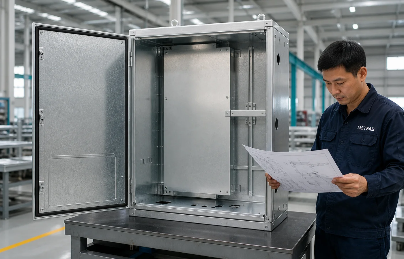
Figure 1: MSTFAB senior quality engineer conducting multi-point CMM coordinate inspection, busbar mounting channel alignment verification, and ground stud torque testing on an empty galvanized power distribution box shell.
1. Power Applications & The IATF 16949 Regulatory Framework
Understanding power distribution box requirements begins with the governing international electrical standards and the stringent quality management principles established by the International Automotive Task Force (IATF).
1.1 Governing Electrical Standards: UL 891, UL 508A, and IEC 61439-1/-2
Low-voltage electrical distribution equipment operates under two dominant global standards:
- North American Standards (UL 891 & UL 508A): UL 891 governs dead-front switchboards rated up to 6,000 A at 600 VAC / 1,000 VDC. It mandates minimum sheet metal thickness based on unsupported panel surface area, busbar clearance barriers, and mechanical structural rigidity. UL 508A applies to industrial control panels, establishing wiring duct clearances, grounding continuity, and short-circuit current ratings (SCCR).
- International Standards (IEC 61439-1 & IEC 61439-2): Governs low-voltage switchgear and controlgear assemblies (PSC-assemblies). It categorizes assemblies into specific “Forms of Internal Separation” that dictate how busbars, functional switching units, and external cable terminals are physically partitioned by sheet metal or insulating barriers.
| IEC 61439-2 Separation Form | Busbar Segregation Architecture | Functional Switching Unit Partitioning | Cable Terminal Isolation | MSTFAB Galvanized Sheet DFM Implementation |
|---|---|---|---|---|
| Form 1 | No internal separation | All units share common cavity | No terminal isolation | Open enclosure body; single sub-panel backplate |
| Form 2b | Separated from functional units | Not separated from each other | Terminals separated from busbars | Galvanized steel barrier plate between busbar and devices |
| Form 3b (Automotive Standard) | Separated from functional units | Functional units separated from each other | Terminals separated from busbars | Modular galvanized divider pans (1.5 mm) per breaker bay |
| Form 4b (Heavy Gigafactory Spec) | Separated from functional units | Functional units separated from each other | Terminals completely segregated per unit | Independent enclosed galvanized cell per breaker & cable run |
1.2 Why IATF 16949 is Mandatory for Automotive Power Enclosure Programs
IATF 16949:2016 is the premier automotive global quality management standard, harmonized across the International Automotive Task Force members. When applied to power distribution box shells, it imposes stringent operational disciplines:
- Strict Defect Prevention & Variation Reduction: Prohibits reliance on end-of-line sorting. Every manufacturing step—laser cutting, CNC press brake forming, robotic welding, Haeger stud insertion, and powder coating—is statistically validated to achieve Cpk ≥ 1.67.
- Process Failure Mode and Effects Analysis (PFMEA): Every potential manufacturing defect (e.g., stud pull-out under busbar weight, weld burn-through, missing ground jumper) is evaluated for Severity, Occurrence, and Detection, with corrective actions driving Risk Priority Numbers (RPN) below 80.
- Formal Engineering Change Control: Once a part design is approved under PPAP Level 3, no tooling change, CNC program revision, raw material supplier change, or machine relocation can occur without prior formal customer notification and re-qualification.
2. Electrodynamic Short-Circuit Forces & Structural Busbar Bracing DFM
The primary mechanical design challenge in high-power distribution cabinets is withstanding electrodynamic short-circuit forces. When a short-circuit fault occurs downstream, instantaneous fault currents surge through the parallel three-phase busbars (L1, L2, L3). In low-voltage systems (480 VAC to 690 VAC), prospective symmetrical short-circuit currents frequently EU REACH Regulation Isc = 25 kA – 65 kA RMS, producing peak asymmetrical currents (Ip) up to:

Figure 2: MSTFAB CMM inspection station verifying center-to-center hole tolerances (± 0.15 mm) on heavy2.5 mmgalvanized busbar support uprights and cross-bracing channels.
2.1 Electrodynamic Lorentz Force Calculations (IEC 60865-1)
Under Ampere’s Force Law and Biot-Savart principles (formalized in IEC 60865-1: Short-circuit currents — Calculation of effects), two parallel busbars carrying instantaneous peak current experience a mutual electrodynamic repulsion force:
-mu_0 = 4π × 10^{-7} H/m(magnetic permeability of free space).
-a: Center-to-center distance between busbar phases (typicallya = 0.080 – 0.120 m).
-L: Unsupported span length between structural busbar support braces (L = 0.300 – 0.500 m).
Engineering Calculation Example: For a50 kA RMSfault withI_p = 110 kA, phase spacinga = 0.100 m, and support spanL = 0.400 m:
Fpeak = (2 × 10^{-7}) × ((110,000)²) / (0.100) × 0.400 = 9,680 N per span (&a≈; 2,176 lbf)
This instantaneous force of nearly10 kNacts within 10 milliseconds, exerting severe cyclic shock loading across the busbar insulator supports and transferring dynamic bending moments directly into the enclosure structural frame.
2.2 Enclosure Structural DFM for Short-Circuit Containment
If an enclosure is constructed from light-gauge sheet metal (1.2 – 1.5 mm) with standard flat unbraced backplates, these massive electrodynamic forces flex the enclosure sidewalls inward. This deflection causes busbar insulators to crack, bringing bare phases into direct contact with the grounded cabinet shell and turning a downstream short-circuit into an catastrophic internal arc flash explosion.
MSTFAB implements robust structural reinforcement DFM:
- Heavy-Gauge2.5 mmGalvanized Support Cross-Channels: Busbar insulator supports mount directly onto CNC roll-formed or press-braked C-channels fabricated from 2.5 mm(12-gauge) DX51D+Z275 galvanized steel. The C-channel geometry increases section modulus (Zxx) by 520% compared to flat sheet.
- Direct Structural Frame Load Transfer: Busbar channels are fastened to the main vertical enclosure frame using high-strength Grade 8.8 M8/M10 flange bolts or welded directly with robotic CMT seams. Dynamic forces bypass the thin external cosmetic skins and discharge directly into the floor-anchored structural uprights.
- Deflection Limit Thresholds: Finite Element Analysis (FEA) ensures that under a65 kAshort-circuit load, maximum structural frame deflection (deltamax) remains strictly below1.5 mm, ensuring busbar phase clearances exceed UL 891 electrical spacing rules (> 25.4 mmthrough air,> 50.8 mmover surface).
3. Arc Flash Venting & Internal Pressure Relief DFM (IEEE C37.20.7 & NFPA 70E)
An electrical arc fault is the most destructive hazard in low-voltage power distribution. Initiated by accidental tool drop, dielectric breakdown, or insulation failure, an arc fault instantly vaporizes solid copper busbars into conductive metallic plasma. Internal air temperatures soar to 10,000^circC-20,000^circC—hotter than the surface of the sun.
3.1 The Physics of Arc Blast Shockwaves
The instantaneous volumetric thermal expansion of superheated air and vaporizing copper (copper expands by 67,000timesits solid volume when vaporized) produces an explosive pressure shock wave. Within5 – 15 millisecondsof arc initiation, internal static pressure inside a sealed enclosure rises to 0.5 – 2.5 bar(7.25 – 36.2 psi).
On a standard2,000 mm × 800 mmenclosure door, an internal pressure of just0.5 bar(50 kPa) exerts a total outward bursting force of:
Without engineered pressure relief mechanisms, standard quarter-turn latches shear instantly, blowing the steel door outward into operating personnel standing in the aisle, followed by a deadly wave of radiant thermal heat and molten shrapnel.
3.2 IEEE C37.20.7 Arc-Resistant Passive Pressure Relief Flaps
Under IEEE C37.20.7 (IEEE Guide for Testing Switchgear for Internal Arcing Faults) Accessibility Type 2B, an arc-resistant enclosure must protect personnel standing at the front, sides, and rear of the enclosure during an internal arc fault. To achieve this life-safety requirement, MSTFAB integrates passive top-venting blast flaps:
- Top-Mounted Blow-Out Flaps: The roof of the enclosure features CNC laser-cut galvanized blast flaps hinged along their rear border and secured with calibrated shear fasteners or stainless steel gravity-loaded spring latches. The flaps are engineered to burst open at an internal threshold pressure of 15 – 25 kPa(2.2 – 3.6 psi), venting explosive gases upward into ceiling plenums within8 ms, before door latches reach their mechanical yield point.
- Reinforced Multi-Point Door Latching: Enclosure doors are secured by heavy-duty 3-point or 4-point cam locking mechanisms with10 mmhardened steel locking rods and heavy-gauge formed door catch brackets that withstand dynamic outward pressure impulses up to 100 kPa.
- Labyrinth Flame & Particulate Quenching Baffles: Beneath the roof blast flaps, MSTFAB integrates multi-stage offset galvanized baffle channels. As superheated gas rushes upward, the tortuous labyrinth path cools the plasma, while stainless steel wire mesh filters capture molten copper and zinc droplets, preventing flaming projectile emission into the facility ceiling.
4. Metallurgy & Material Selection: DX51D+Z275 / G90 Galvanized Steel for Power Enclosures
Why do leading switchgear builders choose continuous hot-dip galvanized steel (ASTM A653 G90 / EN 10346 DX51D+Z275) over plain cold-rolled carbon steel (SPCC) or aluminum for high-power distribution cabinets? The decision is driven by three metallurgical factors: sacrificial cathodic corrosion protection, natural unpainted grounding continuity, and magnetic field shielding.
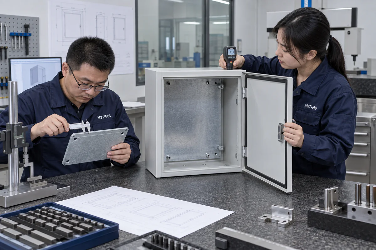
Figure 3: MSTFAB quality engineers verifying zero-spangle surface texture, zinc coating thickness (20 μ m), and diagonal squareness on a welded galvanized distribution box shell.
4.1 Eliminating Condensation Corrosion in High-Current Enclosures
Power distribution boxes generate significant internal heat during operating shifts. When shifts end or equipment powers down, internal temperature drops rapidly, creating dew-point condensation on interior sheet metal surfaces. In standard carbon steel (SPCC) cabinets, condensation causes red rust on unpainted internal corners, tapped holes, and sub-panel backplates within months.
Continuous hot-dip galvanized steel (DX51D+Z275 / G90) incorporates a275 g/m^2zinc mass (20 μ mnominal thickness per side). Zinc provides active sacrificial cathodic protection (E^circ = -0.763 Vvs SHE) that protects exposed steel edges and scratches. When moisture condenses, zinc sacrificially oxidizes, precipitating an insoluble, protective barrier of basic zinc carbonate[Zn_5(CO_3)_2(OH)_6]that prevents red rust formation for over 30 years.
| Substrate Material | Yield Strength (Rp0.2) | Young’s Modulus (E) | Relative Magnetic Permeability (mu_r) | Grounding Surface Conductivity | Power Enclosure Suitability |
|---|---|---|---|---|---|
| Cold-Rolled Carbon Steel (SPCC) | 140 – 260 MPa | 205 GPa | 200 – 500(High EMI shield) | Fails (Requires paint; bare steel rusts) | Poor (Internal rust risks) |
| HDG G90 / DX51D+Z275 (MSTFAB Standard) | 140 – 300 MPa | 205 GPa(High rigidity) | 200 – 500(Superior magnetic shield) | Excellent (Bare zinc groundingR ≤ 10 mω) | Industry Benchmark |
| Aluminum Alloy 5052-H32 | 195 MPa | 70 GPa(3timesmore flexible) | ≈ 1.0(Zero magnetic shielding) | Good (Non-anodized bare metal) | Bows under short-circuit forces |
| Austenitic Stainless Steel 304 | 205 MPa | 193 GPa | ≈ 1.02(Zero magnetic shielding) | PassivatedCr_2O_3adds resistance | High cost (3.5timescost penalty) |
5. Thermal Management, Natural Convection Louvers & IP Sealing Tradeoffs
In high-power distribution boxes, thermal management is a primary functional requirement. High-current copper busbars, circuit breaker thermal trip bi-metals, and contactor coils generate substantial Joule heating (I^2 R). A1,200 Aswitchgear cabinet operating under 80% continuous load typically dissipates between 800 Wand1,800 Wof thermal energy inside the enclosure volume.

Figure 4: MSTFAB technical review of CNC stamped ventilation louver geometry, washable filter media retention brackets, and bottom cable gland plate penetrations.
5.1 Natural Convection Stack Effect (Chimney Effect) DFM
Where environmental conditions permit natural convection ventilation (IP31 to IP54 ratings), MSTFAB optimizes the enclosure geometry to maximize the natural thermal stack effect (chimney effect):
-C_d: Discharge coefficient of the stamped louvers (C_d ≈ 0.60 – 0.65).
-A: Net free ventilation area (A = 0.08 – 0.15 m^2).
-H: Vertical distance between lower intake louvers and upper exhaust louvers (H = 1.2 – 1.8 m).
-T_i, T_o: Internal and external absolute temperatures in Kelvin.
Engineering Outcome: Maximizing vertical separation heightHand positioning exhaust louvers on top-side overhangs generates passive cooling airflows of 120 – 250 m^3/hr, maintaining internal temperatures below+50^circCwithout requiring electrical cooling fans.
5.2 Stamped Louvers vs Fan Cutouts vs Closed-Loop Air Conditioners
MSTFAB supports three standardized thermal management enclosure topologies:
- Downward-Formed Stamped Louvers (IP31 / IP43): Formed on CNC punch presses with integrated fine stainless steel wire mesh (0.8 mmaperture) or synthetic open-cell filter pads. The downward angle prevents falling water drops and conductive shop lint from entering the cabinet.
- Forced-Air Filter Fan Cutouts (IP54): Precision fiber laser cutouts for standardized industrial filter fans (Pfannenberg / Stego / Rittal patterns), incorporating continuous FIPFG perimeter polyurethane gasketing to maintain dust-tight seals.
- Closed-Loop Air Conditioner Cutouts (NEMA 12 / NEMA 4): For harsh EV gigafactory battery electrode coating zones with airborne graphite dust or chemical vapors, cabinets are fully sealed (IP65 / NEMA 12) with side-mount or door-mount cutouts for closed-loop air conditioners, isolating internal electronics from ambient air while extracting up to 5.0 kWof thermal heat.
6. Electrical Grounding Continuity & Bonding DFM: NFPA 79 & UL 508A / UL 891
In a high-power distribution cabinet, electrical grounding is the primary life-safety protection against phase-to-chassis flashover. If a480 VACphase conductor touches the steel enclosure wall, the enclosure frame must safely carry the prospective ground fault current (often exceeding 10 kA) back to the main incoming protective earth (PE) busbar long enough to trip the upstream circuit breaker within0.05 – 0.10 seconds.
6.1 Ground Fault Current Withstand & Bonding Sizing
Under UL 891 Section 8.6 and NFPA 79 Clause 8.2, ground bonding jumpers between movable doors, removable gland plates, and the main enclosure frame must have sufficient ampacity to clear prospective fault currents without burning through or melting:
– Up to 400 AOCPD: Minimum16 mm^2(#6 AWG) tinned-copper braided strap.
-401 Ato 800 AOCPD: Minimum25 mm^2(#4 AWG) tinned-copper braided strap.
-801 Ato 1,600 AOCPD: Minimum35 mm^2(#2 AWG) tinned-copper braided strap.
– Over 1,600 AOCPD: Dual35 mm^2braided straps or solid3.0 × 25 mmcopper busbar link.
Bonding Resistance Acceptance Criterion:Rbond ≤ 0.10 Omegaper UL 508A / UL 891.
MSTFAB Production Limit:Rbond ≤ 0.010 ω(10 mω) tested at 30 A.
6.2 Automated PEM Clinch Ground Studs & Masking Strategy
Because the exterior of the enclosure is coated with an electrically insulating polyester powder coat (80 – 120 μ m, dielectric strength> 5 kV), standard mechanical bolting through painted holes results in open-circuit grounding failure.
MSTFAB enforces a rigorous grounding hardware insertion protocol:
- Dedicated heavy M8 or M10 copper-plated steel self-clinching studs (Haeger automated insertion) are pressed into the door panel, frame uprights, and gland plates prior to painting. Clinch force is monitored to guarantee push-out resistance> 4.5 kNand torque-out resistance> 25 N·m.
- Ground studs and a circular25 mmsurrounding bonding landing zone are masked with high-temperature (230^circC) silicone caps prior to pretreatment and powder coating.
- After powder curing, masking is removed, revealing bare, highly conductive zinc. Conductive anti-oxidation synthetic grease is applied, and braided straps are secured with 316 stainless steel serrated conical Belleville spring washers that bite into the zinc layer, ensuring zero contact resistance.
7. Automated 7-Stage Nano-Ceramic Pretreatment & Industrial Powder Finishing
Power distribution cabinets in automotive factories and industrial plants are exposed to demanding chemical and mechanical wear: airborne stamping oils, metal grindings, hydraulic fluids, and frequent tool impacts from maintenance personnel. Achieving a durable, scratch-resistant finish over a galvanized substrate requires an engineered chemical conversion system.
7.1 The Automated Zirconium Nano-Ceramic Conversion Sequence
Applying powder coat directly to raw galvanized steel causes outgassing pinholes and saponification delamination. MSTFAB processes all power distribution enclosures through an automated 7-stage conveyorized immersion/spray pretreatment line:
- Stage 1: Heavy-Duty Alkaline Degreasing (55^circC-60^circC): Removes mill oils and forming lubricants using engineered surfactants.
- Stage 2: Primary Cascade City Water Rinse: High-volume water spray prevents bath carryover.
- Stage 3: Acidic Micro-Etch & Deoxidizer: Mild fluorophosphoric acid dissolves surface zinc oxides and micro-roughs the zinc crystal facets, tripling mechanical surface area.
- Stage 4: Reverse-Osmosis (RO) Pure Water Rinse: Conductivity strictly held below20 μ S/cm.
- Stage 5: Zirconium Nano-Ceramic Conversion (25^circC-32^circC): Hexafluorozirconic acid (H_2ZrF_6) deposits an amorphous nano-ceramicZrO_2conversion coating (30 – 65 mg/m^2,25 – 50 nmthickness), establishing covalent chemical bonding sites for polyester resins.
- Stage 6: Ultra-Pure DI Water Halo Rinse: Conductivity< 5 μ S/cmensures zero ionic contamination.
- Stage 7: Indirect Convection Dry-Off Oven (115^circC-125^circC): 10-minute dry-off ensuring complete moisture evaporation from internal frame corners and blind threaded studs.
7.2 Industrial Powder Coating Performance & ASTM Standards
MSTFAB applies thermoset super-durable TGIC polyester or epoxy-polyester hybrid powder coatings (80 – 120 μ mDFT) formulated with degassing additives to eliminate pinholes over the galvanized zinc substrate:
| Coating Property & Standard | UL 891 / UL 508A Baseline Requirement | MSTFAB Engineered Finish Performance |
|---|---|---|
| Dry Film Thickness (ASTM D7091) | 50 – 65 μ m(2.0 – 2.5 mils) | 80 – 120 μ m(3.1 – 4.7 mils) |
| Cross-Hatch Adhesion (ASTM D3359) | Class 3B – 4B | Class 5B (100% adhesion, zero lattice detachment) |
| Pencil Hardness (ASTM D3363) | H | 2H – 3H (Gouge resistant to steel tools) |
| Direct Impact Resistance (ASTM D2794) | 40 in-lbs(4.5 J) | ≥ 80 in-lbs(9.0 J) zero cracking |
| Salt Fog Corrosion (ASTM B117) | 200 hoursindoor baseline | 1,200+ hourswith zero creep (>6x baseline) |
| Standard Color Palette | ANSI 61 Light Gray | ANSI 61, RAL 7035, RAL 7032, Munsell 5Y7/1, Custom OEM |
8. IATF 16949 Quality Assurance, SPC, Gage R&R & PPAP Level 3 Deliverables
MSTFAB operates under an integrated IATF 16949:2016 and ISO 9001:2015 Quality Management System. Every high-power galvanized distribution box project is managed through formal automotive Advanced Product Quality Planning (APQP) protocols.

Figure 5: MSTFAB environmental test booth conducting calibrated water spray ingress verification and door seal deflection validation on a finished power distribution enclosure.
8.1 Multi-Stage Production Control Plan (PCP)
Table 4 outlines our serial inspection regime from raw steel inception to final dispatch:
| Inspection Station | Controlled Parameter | Inspection Tooling & Standard | Sampling Frequency & Acceptance Criteria |
|---|---|---|---|
| 1. Incoming Material | Zinc mass (275 g/m^2) & steel chemistry | XRF spectrometer; Mill Test Cert (EN 10204 3.1) | 100% of coils; Zinc mass≥ 275 g/m^2; Lead < 0.005% |
| 2. Laser & Forming | Busbar hole centers, diagonal squareness, bend angles | Hexagon 3D CMM / digital height gauge | FAI + 3 units/shift; tolerance± 0.20 mm;Cpk ≥ 1.67 |
| 3. Hardware Clinch | PEM stud push-out and torque-out resistance | Calibrated torque wrench / digital force load cell | 1 stud/batch; Torque> 25 N·m; Push> 4.5 kN |
| 4. Robotic Welding | Seam penetration, frame squareness, zero spatter | Visual inspection (ISO 5817 Level B) / Dye penetrant | 100% of weld seams; zero detectable porosity/spatter |
| 5. Powder Coating | Dry film thickness & cross-hatch adhesion | Magnetic DFT gauge; Cross-hatch tape (ASTM D3359) | DFT80 – 120 μ m; Adhesion Class 5B (100% pass) |
| 6. Electrical Bonding | Ground continuity per UL 891 / NFPA 79 | 4-Wire Kelvin Micro-ohmmeter @ 30A | 100% of finished units;Rbond ≤ 0.010 ω |
| 7. Ingress Sealing | Door gasket deflection & water spray test | Optical feeler gauge; water spray test booth | 1 unit per 100 pcs; Gasket compression35 ± 5% |
8.2 Complete AIAG PPAP Level 3 Submission Package
For every automotive tier-1 power enclosure program, MSTFAB provides a formal AIAG Production Part Approval Process (PPAP) Level 3 submission dossier:
- Part Submission Warrant (PSW): Formally executed warrant certifying tooling, process, and dimensional conformity.
- Design Records & Ballooned Drawings: 100% of dimensions and GD&T feature control frames ballooned and measured on 3D CMM.
- Process FMEA (PFMEA): Comprehensive analysis of potential failure modes with Risk Priority Numbers (RPN) strictly< 80.
- Process Capability Studies (Cpk): Statistical evidence demonstratingCpk ≥ 1.67on critical busbar mounting centers, door seal flatness, and latch hole datums.
- Measurement Systems Analysis (Gage R&R): Variable and attribute Gage R&R studies confirming measurement variation contributes< 10% to total process tolerance.
- Material & Coating Test Certifications: Complete mill traceability certificates (EN 10204 3.1), salt fog test reports (ASTM B117), and RoHS/REACH compliance documentation.
9. Real-World Case Study: Automotive Gigafactory Battery Module Assembly Line Distribution Box
To evaluate the engineering performance and financial benefits of IATF 16949 certified galvanized power distribution boxes, we examine a high-volume manufacturing contract executed for a major automotive tier-1 electrification systems OEM based in Auburn Hills, Michigan, USA.
9.1 The Operational Challenge
The client was contracted to engineer and commission the automated battery module assembly and laser welding lines for a new EV gigafactory in Georgia, USA. The program demanded 420 heavy distributed power junction and feeder cabinets (1,600 mm (H) × 1,000 mm (W) × 400 mm (D)) distributing800 A / 480 VACpower to high-frequency laser welders, robotic servo presses, and automated guided vehicle (AGV) fast-charging stations.
The previous supplier, a domestic US commercial sheet metal job shop, experienced severe project failures:
- Short-Circuit Frame Distortion: During electrical type testing at an independent laboratory, prospective short-circuit fault current (35 kA / 1 second) caused the unbraced backplate to bow by 12 mm, causing two phases to flash over to the enclosure wall.
- Quality System Gaps: The supplier was only ISO 9001 certified and lacked IATF 16949 APQP capabilities, resulting in missing material certs, inconsistent hole centerlines (Cpk < 1.0), and a 16-week delivery backlog that threatened plant launch.
- Internal Rust: Moisture condensation inside cabinets during transport caused red rust to bloom on unpainted cold-rolled steel backplates.
9.2 The MSTFAB Engineering Solution
MSTFAB took over the enclosure shell contract, executing a comprehensive DFM redesign under IATF 16949:
- Substrate Upgrade: Replaced cold-rolled SPCC with heavy2.5 mmcontinuous hot-dip galvanized DX51D+Z275 (275 g/m^2zinc mass), guaranteeing permanent sacrificial rust protection.
- FEA Short-Circuit Busbar Cross-Bracing: Integrated two heavy-gauge C-channel structural cross-members welded to the main frame, reducing maximum short-circuit frame deflection to 0.8 mmunder 35 kAfault simulation.
- IEC 61439 Form 3b Internal Separation: Fabricated modular galvanized internal phase barriers and segregated breaker pans, preventing arc propagation between bays.
- Top Arc Flash Relief Flaps: Engineered top pressure relief blow-out flaps calibrated to burst open at 20 kPa, directing blast gases upward and protecting operators.
- Finish & Grounding: Automated 7-stage zirconium nano-ceramic conversion with ANSI 61 gray polyester powder (90 μ m), unpainted conductive backplates (Rbond ≤ 0.008 ω), and automated M10 copper-plated PEM ground studs.
- Automotive Quality Release: Full AIAG PPAP Level 3 package submitted and approved within 3 weeks.
9.3 Results and Multi-Metric Before vs After Analysis
All 420 power distribution boxes were delivered on schedule across four planned production releases. The client achieved100% first-time electrical commissioning pass rates and significant cost savings:
| Performance & Cost Metric | Legacy US Commercial Job Shop (SPCC) | MSTFAB IATF 16949 Galvanized Solution | Net Engineering & Operational Benefit |
|---|---|---|---|
| Unit Procurement Cost | 685.00 USD / unit | 452.00 USD / unit | 34.0% direct unit cost reduction (97,860 savings) |
| Manufacturing Lead Time | 14 – 16 weeks (Chronic delays) | 3.5 weeks (Automated cell production) | 76% reduction in manufacturing turnaround |
| Short-Circuit Test Deflection | 12.0 mm deflection (Flashover failure) | 0.8 mm deflection (100% pass @ 35 kA) | Zero electrical breakdown; certified type test pass |
| Process Capability (Cpk) | Cpk = 0.85 – 1.10 (Out-of-spec holes) | Cpk ≥ 1.74 (Statistical control) | Zero panel shop assembly fitting rework |
| Corrosion / Condensation Rust | Red rust on backplates after 6 weeks | 0% rust (G90 sacrificial zinc protection) | Eliminated cosmetic warranty claims |
10. Frequently Asked Questions (FAQ): IATF 16949 Galvanized Power Distribution Boxes
Here are 32 in-depth technical answers addressing the most common design, regulatory, short-circuit, metallurgical, and manufacturing questions submitted by power systems engineers and switchgear procurement specifiers:
1. What is the scope of IATF 16949 certification for a power distribution box project?
IATF 16949 certifies MSTFAB’s Quality Management System for the design, precision sheet metal fabrication, robotic welding, automated nano-ceramic pretreatment, powder coating, hardware clinch insertion, and final assembly of the empty enclosure shells. Electrical integration (busbars, breakers, wiring) and completed assembly type testing are performed by the electrical panel builder or switchgear OEM under their own UL/IEC listings.
2. What governing standards apply to low-voltage power distribution enclosures?
Key standards include UL 891 (Dead-Front Switchboards), UL 508A (Industrial Control Panels), IEC 61439-1 and IEC 61439-2 (Low-voltage switchgear assemblies), IEEE C37.20.7 (Arc-resistant testing), NFPA 79 (Electrical Standard for Industrial Machinery), and NFPA 70E (Standard for Electrical Safety in the Workplace).
3. What is the difference between IEC 61439 Form 1, Form 2b, Form 3b, and Form 4b?
Forms define internal separation: Form 1 has no internal barriers. Form 2b separates busbars from functional units. Form 3b separates busbars from functional units AND separates functional units from each other, while keeping terminals grouped. Form 4b provides complete individual segregation: busbars, functional units, and external cable terminals are each enclosed in dedicated, separate metallic compartments.
4. How does MSTFAB engineer enclosures to withstand short-circuit forces?
We incorporate heavy-gauge (2.5 – 3.0 mm) DX51D+Z275 galvanized steel structural C-channels and formed uprights. Finite Element Analysis (FEA) validates that peak electrodynamic repulsion forces (up to 15 – 30 kN/m during a 50 kA fault) are transferred directly into the floor anchors, limiting frame deflection below 1.5 mm to prevent busbar insulator cracking.
5. What is the function of top-mounted arc flash pressure relief blast flaps?
In the event of an internal arc flash, internal air expands rapidly, creating bursting shockwaves (0.5 – 2.5 bar). Top blast flaps are calibrated to burst open at 15 – 25 kPa, venting explosive plasma gases upward into ceiling plenums within 8 milliseconds to prevent the front doors from blowing outward into maintenance personnel.
6. Why is continuous galvanized steel (G90) superior to cold-rolled steel (SPCC) for power boxes?
Heavy power components generate cyclic heat that induces dew condensation on interior walls during plant shutdown. SPCC carbon steel rusts rapidly inside unpainted joints and tapped holes. Continuous hot-dip galvanized steel (ASTM A653 G90 / DX51D+Z275, 275 g/m² zinc mass) provides sacrificial cathodic protection that permanently prevents red rust for over 30 years.
7. How does galvanized steel enhance electromagnetic compatibility (EMC/EMI) in switchgear?
Galvanized carbon steel possesses high relative magnetic permeability (μr &a≈; 200 – 500), providing substantial magnetic field absorption against low-frequency interference (10 kHz – 1 MHz) generated by large step-down transformers and inductive motor loads. In contrast, aluminum and stainless steel are non-magnetic (μr &a≈; 1.0) and offer zero magnetic shielding.
8. What sheet metal thickness does MSTFAB recommend for power distribution boxes?
We recommend 2.0 mm (14-gauge) for external cosmetic side panels and doors, and 2.5 – 3.0 mm (12- to 11-gauge) for main structural uprights, busbar support cross-members, sub-panel backplates, and floor-mounting seismic channels.
9. How does natural convection chimney ventilation work in power cabinets?
Natural convection relies on the thermal stack effect: internal air warmed by busbar I² R losses becomes less dense and rises, drawing cool ambient air through lower intake louvers and discharging hot air through upper roof louvers. By maximizing vertical separation (H ≥ 1.4 m), passive airflow rates of 120 – 250 m³/hr are achieved without electric fans.
10. How is grounding continuity verified under UL 891 and NFPA 79?
Dedicated M8 or M10 copper-plated PEM clinch studs are inserted prior to coating and protected with silicone masking caps. After baking, unmasked bare zinc lands receive conductive anti-oxidation grease and heavy braided tinned-copper bonding straps (25 – 35 mm²). Bonding resistance is tested at 30 A using a 4-wire Kelvin micro-ohmmeter to confirm Rbond ≤ 0.010 Ω (limit 0.10 Ω).
11. What is the role of the 7-stage nano-ceramic conversion pretreatment?
Zirconium fluorometallic acid micro-etches the zinc spangle and deposits an ultra-thin (25 – 50 nm) amorphous zirconium dioxide (ZrO2) conversion layer (30 – 65 mg/m²). This layer passivates the zinc against saponification, prevents outgassing pinholes, and establishes covalent bonds with the polyester powder coating, achieving Class 5B cross-hatch adhesion.
12. Why does MSTFAB supply unpainted galvanized sub-panels?
Unpainted G90 galvanized backplates provide zero-resistance electrical grounding across their entire surface. Switchgear builders can mount DIN rails, grounding busbars, and circuit breaker bases directly without tedious, labor-intensive paint scraping or masking operations.
13. What latching systems are specified for arc-resistant enclosures?
We integrate heavy-duty multi-point latching rod systems featuring 10 mm hardened steel locking rods and heavy-gauge formed door catch brackets actuated by a single center quarter-turn handle. Steel locking rods engage top and bottom frame members, withstanding outward dynamic pressure pulses up to 100 kPa.
14. How does Fronius Cold Metal Transfer (CMT) welding benefit galvanized power boxes?
CMT uses high-frequency mechanical wire retraction to decouple droplet detachment from arc current, cutting heat input by 50%. This minimizes zinc vaporization, completely eliminates weld spatter, and prevents frame burn-through while leaving adjacent zinc sacrificial protection intact.
15. What documentation is included in an MSTFAB AIAG PPAP Level 3 package?
Our PPAP Level 3 package includes: Part Submission Warrant (PSW), Process Flow Diagram, PFMEA, Control Plan, Ballooned Engineering Drawings, 100% CMM Dimensional Layout, Material Mill Test Certificates (EN 10204 3.1), Salt Spray Test Reports (ASTM B117), Coating Thickness Reports, and Statistical Process Capability Studies (Cpk ≥ 1.67).
16. Can bottom gland plates be pre-cut for heavy incoming power cables?
Yes. We pre-cut all conduit knockouts or cable gland entries (e.g., M40, M50, M63, or 2-inch to 4-inch NPT) on CNC fiber lasers on removable 2.5 mm galvanized or non-ferrous aluminum gland plates. Using aluminum gland plates prevents eddy current heating around single-conductor AC cables.
17. Why are aluminum gland plates used for single-core AC cable entries?
When individual single-core AC cables carrying > 200 A pass through individual holes in a magnetic steel plate, the alternating magnetic field induces circular eddy currents in the steel, generating severe localized induction heating that melts cable insulation. Aluminum is non-ferromagnetic (μr &a≈; 1.0), eliminating inductive heating.
18. What powder coating colors are standard for industrial power distribution?
ANSI 61 Light Gray is the North American standard for switchboards and control centers. Light Gray RAL 7035 is widely specified for international IEC switchgear. Custom colors—including safety yellow, high-visibility white, or custom machinery accents—are readily accommodated.
19. What is the typical cost reduction of galvanized steel versus stainless steel for power boxes?
An engineered galvanized steel distribution box shell delivers a 35% – 50% cost reduction compared to 304 stainless steel, and up to 60% compared to 316 stainless steel, due to lower material costs, faster fiber laser cutting, and automated powder coating.
20. How does MSTFAB ensure dimensional squareness across large cabinets?
Cabinets are welded inside rigid pneumatic clamping jigs that lock all frame uprights during robotic CMT welding. Diagonal squareness is verified on 3D laser arms to ensure diagonal variance remains within ± 0.35 mm across a 2,000 mm diagonal.
21. Can lifting eyes be provided for overhead crane rigging in automotive plants?
Yes. We integrate internal reinforcement spreader channels and tapped bosses for certified 316 stainless steel eye bolts, engineered per ASME B30.20 to support up to 1,000 kg total cabinet rigging weight with a 5:1 design safety factor.
22. What seismic acceleration ratings can MSTFAB enclosures achieve?
Our heavy-gauge galvanized enclosure structures are engineered to satisfy ASCE 7-16 Chapter 13 and IEEE 693 high-seismic requirements (SDS = 2.0g), featuring 3.0 mm welded base channel feet and corner gussets capable of withstanding dynamic horizontal shear forces > 1.5× operating weight.
23. What maximum cabinet dimensions can MSTFAB manufacture?
We manufacture single-door, double-door, and multi-bay modular power switchgear suites up to 2,500 mm (H) × 1,600 mm (W) × 1,000 mm (D), supported by 4,000 mm CNC press brakes and automated powder coating lines.
24. How are power distribution enclosures packaged for overseas shipment?
Enclosures are vacuum-sealed inside vapor corrosion inhibitor (VCI) bags with silica desiccant, protected with heavy high-density molded foam corner caps, boxed in heavy corrugated cartons, and strapped to ISPM-15 fumigated heat-treated wooden export pallets.
25. What is the typical prototype lead time versus mass production?
Prototypes with full CNC laser cutting, bending, robotic CMT welding, and manual powder finishing are delivered in 7 to 10 business days. Serial production orders (50 to 500 units) ship in 3 to 4 weeks following PPAP Level 3 approval.
26. What minimum order quantity (MOQ) does MSTFAB require?
We support flexible procurement: prototype qualification orders have an MOQ of 1 piece. For serialized production under contract manufacturing blanket agreements, typical batch releases range from 15 to 200 units per scheduled release.
27. How does MSTFAB prevent zinc micro-blistering during powder baking?
Trapped air and moisture in galvanized crystalline structures can outgas during oven baking (200°C). MSTFAB micro-etches the zinc spangle during 7-stage pretreatment, bakes enclosures in a high-velocity dry-off oven at +125°C, and utilizes powder resins formulated with degassing additives to ensure a smooth, pinhole-free finish.
28. Can interlock mechanisms be pre-installed for rotary disconnect switches?
Yes. Under UL 508A and NFPA 79, power enclosures must prevent the door from opening when the main disconnect switch is energized. MSTFAB pre-machines mounting cutouts and installs mechanical door interlock linkages for major disconnect switch brands (ABB, Schneider Electric, Eaton, Siemens).
29. How does MSTFAB ensure Gage R&R compliance on critical dimensions?
Under IATF 16949 Section 7.1.5, measurement tooling undergoes Gage R&R analysis using 10 parts measured 3 times across 3 independent operators. We calibrate coordinate measuring machines (CMMs) and laser arms to ensure total measurement system variation contributes < 10% to total product tolerance.
30. Can window doors be integrated for thermal infrared (IR) scanning of busbars?
Yes. We pre-punch mounting ports for industrial infrared (IR) viewing inspection windows (Fluke / IRISS). This allows facility maintenance teams to conduct periodic infrared thermographic inspections of busbar bolted joints under full electrical load without opening the energized cabinet door.
31. How does MSTFAB support DFM optimization for custom power distribution shells?
Our engineering team conducts full 3D CAD DFM analysis (SolidWorks / Creo / STEP models) to optimize sheet metal nesting, standardize bend radii, eliminate unnecessary weld joints via complex press-brake hemming, ensure optimal robotic gasket paths, and guarantee full tool access for Haeger hardware insertion.
32. How can an engineering team initiate a custom IATF 16949 power box RFQ with MSTFAB?
Submit your 3D CAD models (STEP, IGES, SolidWorks) and 2D engineering drawings with ballooned tolerances, short-circuit ratings, and thermal specifications to [email protected]. Our power systems engineering team provides a full DFM analysis, preliminary tooling plan, and formal quotation within 24 hours.
Build Certified IATF 16949 Galvanized Power Distribution Boxes with MSTFAB
Protect your high-current electrification investments with automotive-grade precision. MSTFAB delivers heavy galvanized steel distribution box shells engineered for short-circuit withstand, arc flash pressure relief, and 7-stage nano-ceramic finishing with full AIAG PPAP Level 3 documentation.
 WeChat Contact
 WhatsApp Me Directly