⚡ Direct Answer: How to Design Sheet Metal Ventilation Louvers for Electrical Enclosures?
Electrical enclosure ventilation louver DFM requires balancing convective heat rejection with NEMA/IP ingress protection. Key engineering rules include: 1) Standardize Louver Tooling (use standard 76mm, 102mm, or 152mm form tools to avoid $600+ custom punch fees); 2) Orient Louver Openings Downward with a 45° downward draft to prevent falling water droplet ingress; 3) Maintain Minimum 3× T Bridge Spacing between parallel louver rows to avoid sheet metal buckling; and 4) Integrate Washable Stainless Mesh Filters inside the enclosure door to block dust while preserving CFM airflow.
OEM BUYER GUIDE · SHEET METAL INTERFACE DFM
Indoor enclosure ventilation DFM begins after the OEM defines the thermal requirement. The sheet metal job is to turn that requirement into repeatable louvers, cutouts, frames, hoods and service clearances without weakening the panel or promising airflow that nobody measured.
Quick Answer
Freeze the ventilation method, purchased fan or filter envelope, opening location, louver direction, free-area requirement, hole-to-bend clearance, reinforcement, drip path, removal direction, coating condition and first-article checks before production.
MSTFAB fabricates empty custom sheet metal enclosure shells and mechanical ventilation interfaces from buyer-approved drawings. We do not calculate the equipment heat load, select fans or filters, supply powered cooling systems, wire controls, validate the final airflow or certify the completed enclosure.
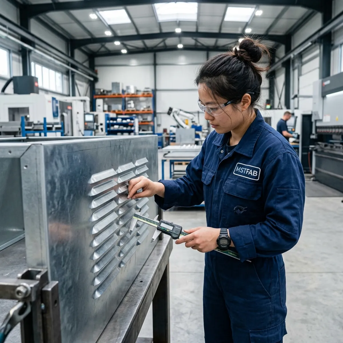
MSTFAB can fabricate
- Laser-cut vent and fan openings
- Formed louvers and perforated panels
- Filter frames, retainers and access covers
- Drip shields, baffles and reinforcement flanges
- PEM hardware, welding and powder coating
- Mechanical first-article inspection
The OEM or integrator controls
- Heat load, target temperature and airflow
- Fan, filter, guard and thermal component selection
- Pressure drop and internal air path
- Electrical wiring, controls and safety
- Final ingress, thermal and compliance testing
Start with the Ventilation Method
Louvers, perforations, fan cutouts and filter frames are not four artistic variations of the same hole. Each creates a different manufacturing and service problem.
Formed louvers
Need tooling-compatible length, pitch, depth, direction and edge clearance.
Fan openings
Remove panel structure and require a controlled hole pattern and support condition.
Filter frames
Need fit, retention, sealing land and a real removal path after installation.
The OEM should provide the mechanical envelope and functional requirement. The fabricator can then review whether the panel can be cut, formed, welded, coated and inspected consistently. “Add some ventilation” is a design mood, not a production release.

Free Area Is Not the Same as the Rectangle on CAD
A louver bank may occupy a large rectangular zone while its open area is much smaller. The formed blade, pitch, material thickness, mesh, filter and protective hood all affect the usable path. The buyer should define the required free area or approve the selected louver geometry rather than assume the outline equals airflow.
MSTFAB can measure blade length, pitch, opening and pattern location. We do not convert those dimensions into a guaranteed cabinet temperature. That requires the OEM’s thermal model or test with the final equipment, fan, filter and installation condition.
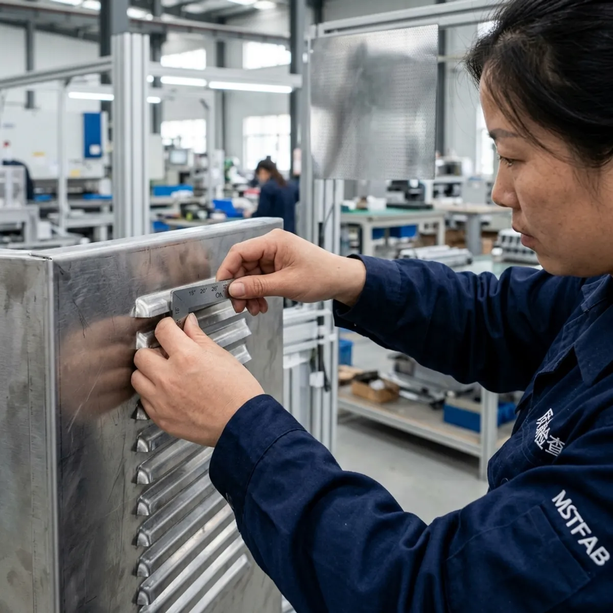
Louver Direction Must Match the Actual Installation
Most downward-facing louvers are intended to reduce direct entry from above, but the useful direction depends on the installed orientation and exposure. Rotate a panel during assembly and a sensible louver can become a small metal scoop.
Show the cabinet top, outside surface and airflow direction on the drawing. Use asymmetric features or clear orientation marks where a panel could be installed upside down. The factory should not have to identify “down” from a marketing render.
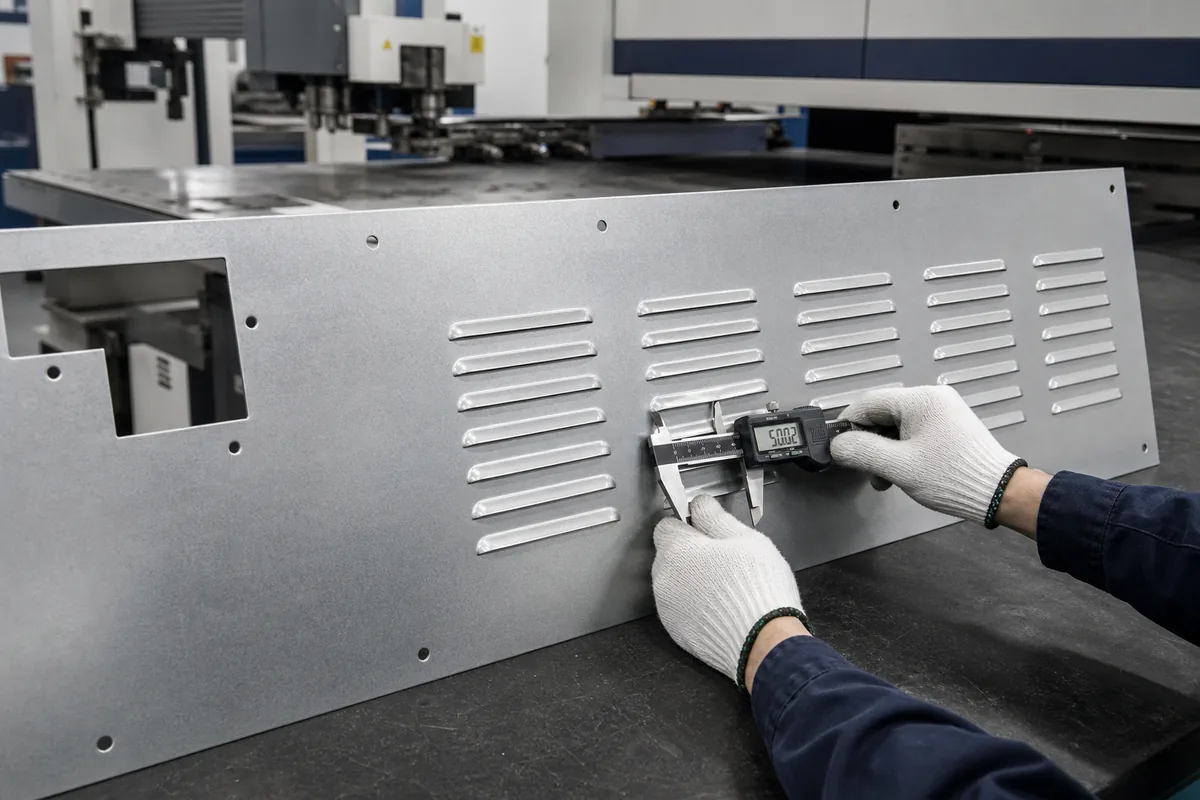
Keep Formed Louvers Away from Bend Lines
A louver formed too close to a return flange may distort during panel bending or interfere with tooling. The required clearance depends on louver depth, sheet thickness, flange height, bend radius, tool shape and forming sequence.
Share the full formed model, not only a flat DXF. The supplier should review whether the louver is punched before bending, whether the pattern weakens the bend zone and whether the finished blade remains inside the allowed envelope.
Drawing trap: the louver fits in flat view
That proves only that two outlines do not overlap on a screen. Press-brake tooling is three-dimensional and less impressed by optimism.
Dense Patterns and Large Cutouts Change Panel Stiffness
Rows of louvers interrupt the sheet and can make a tall side panel flexible. A large fan opening removes even more structure. Door handling, vibration, gasket compression and shipping loads may reveal the weakness long before airflow becomes the interesting problem.
Possible responses include return flanges, local frames, formed beads, thicker material or revised opening location. The OEM approves the structural requirement; MSTFAB can review practical fabrication options and measure the agreed result.
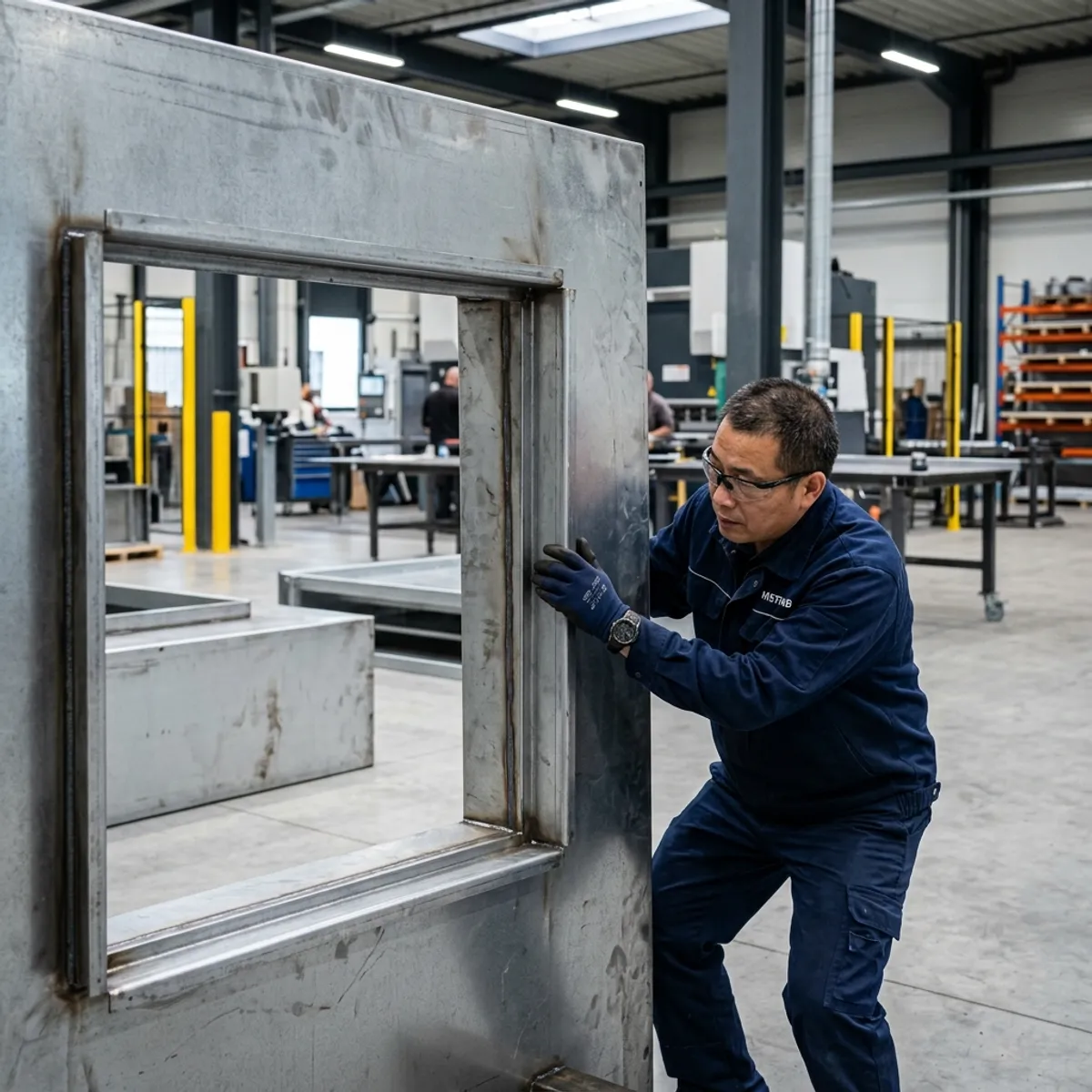
Fan Cutouts Need a Complete Mechanical Envelope
Provide the purchased fan or guard drawing with body size, cutout, hole pattern, fastener type, cable or connector keep-out, airflow direction and service space. If studs or PEM hardware are required, define edge distance and installation side.
Check internal interference with mounting plates, rails and wiring routes. A fan that fits the side panel but collides with the mounting plate is technically installed only in the most philosophical sense.

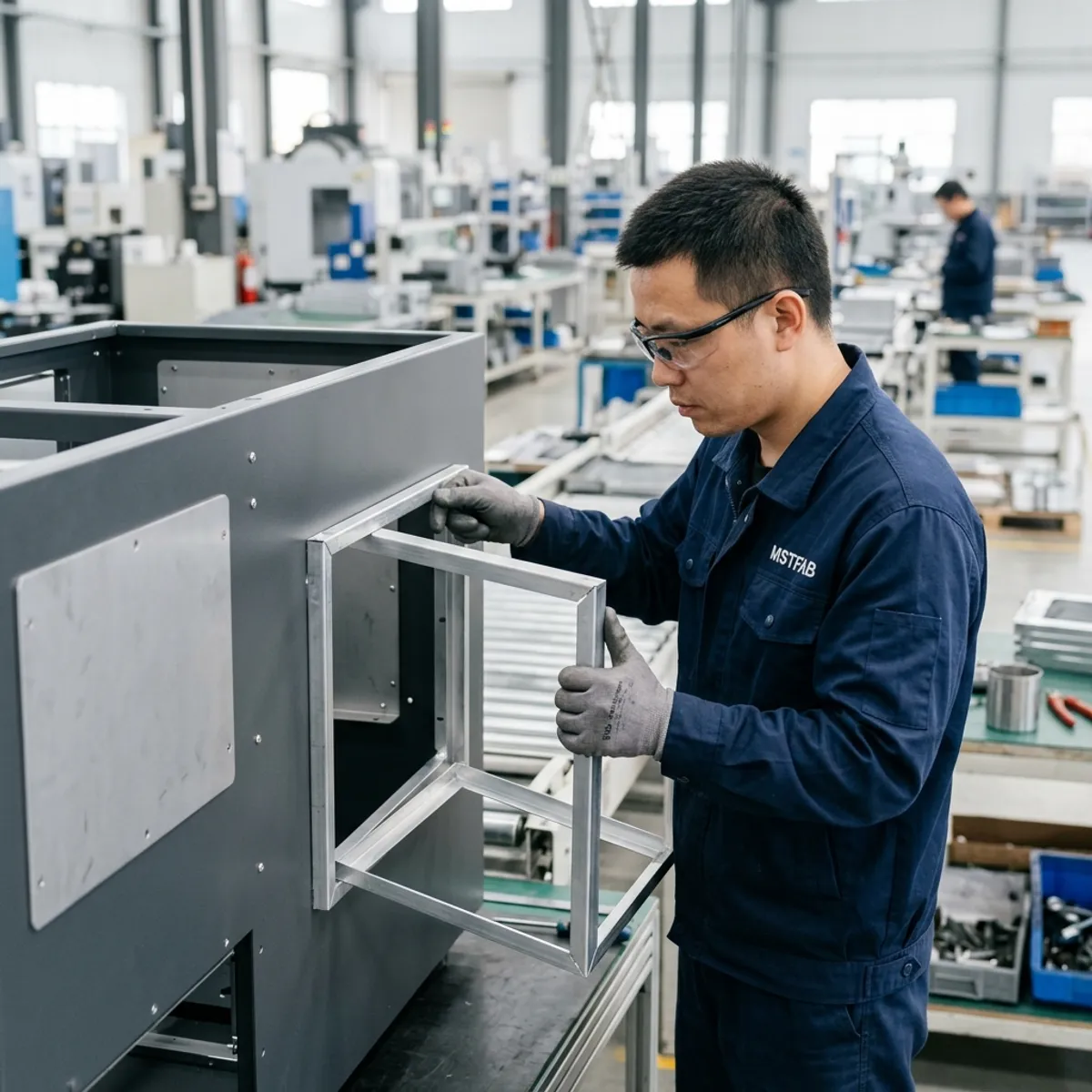
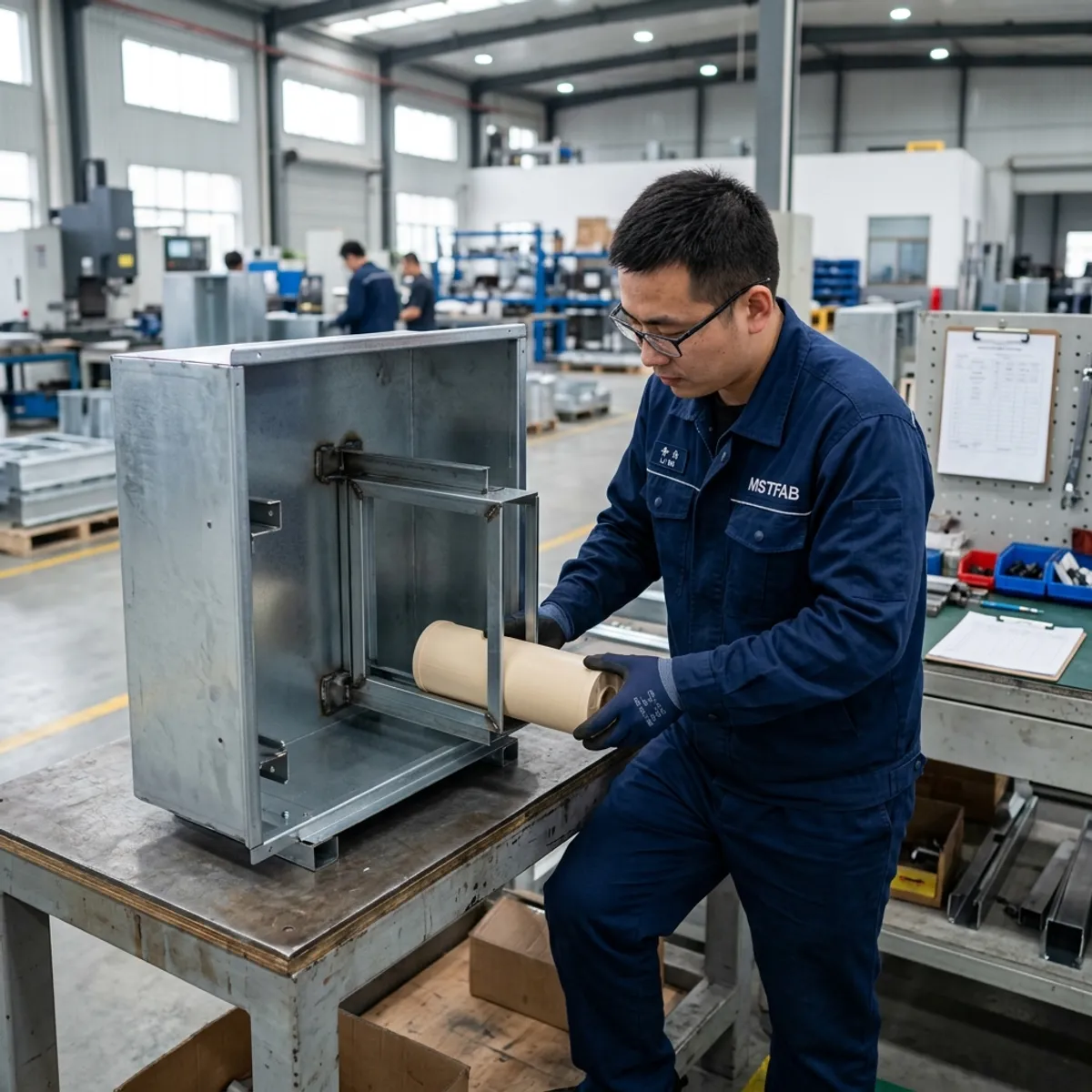
Filter Frames Must Be Replaceable in the Real Cabinet
A filter frame can fit perfectly during bench assembly and become impossible to remove after the cabinet is mounted beside a wall. State the removal direction, pull distance, grip clearance, retaining method and allowable frame play.
Use the actual purchased filter or an approved dummy for first-article fit. Define whether the frame is checked before or after coating and how the sealing land is inspected. The fabricator can verify fit and access; the OEM owns filter performance and maintenance interval.
Drip Shields and Baffles Need a Defined Liquid Path
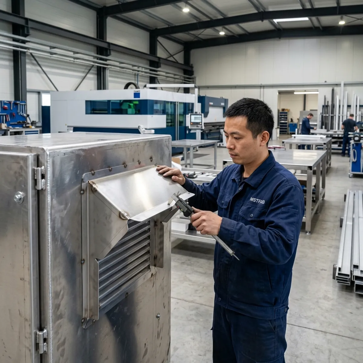
A hood above a louver can reduce direct line-of-sight exposure, but it also changes free area, pressure drop and service access. Define where incidental liquid should land and where it should leave the shell. Avoid seams, fasteners or brackets that create a puddle above the opening.
This geometry does not independently establish an IP or NEMA rating. IEC 60529 classifies degrees of protection provided by complete enclosures; the final assembly and specified test condition matter. The OEM should define the target and validation plan. For the adjacent geometry topic, see our machinery enclosure drip-path DFM guide.
Coating, Mesh and Hardware Change the Finished Interface
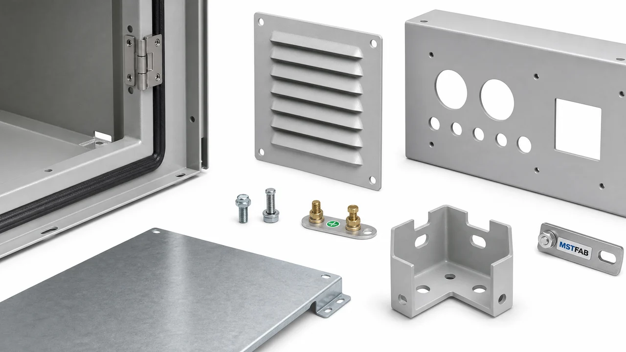
Powder coating adds thickness around frames, studs and sliding parts. Welded mesh can distort a thin panel. Adhesive-backed seals need a clean, flat land. Define masking, grounding areas, cosmetic class, acceptable sharpness and finished dimensions.
If mesh is supplied, specify material, wire or perforation pattern, attachment method and allowable edge condition. If it is buyer-installed, provide the keep-out and mounting features instead. MSTFAB should not guess which purchased component procurement will select next month.
First-Article Evidence Procurement Can Use
| Feature | Mechanical evidence | OEM responsibility |
|---|---|---|
| Louver pattern | Location, pitch, blade length, opening and direction | Approve airflow requirement and geometry |
| Fan opening | Cutout, hole pattern, flatness and hardware position | Select fan, guard and electrical integration |
| Filter frame | Finished fit, retention and removal-path demonstration | Approve filter performance and maintenance plan |
| Drip shield | Projection, overlap, drain direction and opening clearance | Define exposure and final ingress test |
| Panel stiffness | Flatness, reinforcement position and agreed physical check | Define load and acceptance criteria |
Evidence boundary
MSTFAB can manufacture and document drawing-controlled mechanical features. A dimensional report or filter-fit video does not prove final airflow, cooling capacity, dust performance or ingress protection. Those results depend on the complete assembled equipment and the OEM’s test method.
Primary-source context: the official IEC 60529 IP Code publication defines enclosure protection classification. The buyer should identify the applicable standard and acceptance plan.
RFQ Checklist
- STEP or STP enclosure assembly
- Controlled 2D drawings and revision
- Installed orientation and outside surface
- OEM thermal requirement and airflow direction
- Purchased fan, filter, guard and mesh data
- Louver length, pitch, depth and direction
- Required free area or approved pattern
- Fan cutout and mounting-hole pattern
- Hole-to-bend and edge clearances
- Panel stiffness and reinforcement requirement
- Filter removal direction and pull distance
- Drip shield, baffle and discharge direction
- PEM hardware and tool access
- Mesh attachment responsibility
- Coating, masking and finished-size notes
- FAI gauge, dummy parts and records
Frequently Asked Questions
Can MSTFAB calculate the required airflow?
No. The OEM or thermal engineer defines heat load, airflow and component performance. MSTFAB reviews and manufactures the corresponding sheet metal interfaces.
Are formed louvers better than perforated holes?
They solve different mechanical and exposure needs. The choice depends on required free area, direction, tooling, panel strength, appearance and the OEM’s final test plan.
Can a drip hood make the enclosure IP rated?
No. It can support a liquid-management design, but the target rating applies to the defined complete enclosure and test condition.
What should be checked on the first article?
Check pattern location, louver geometry, cutout and hole position, flatness, frame fit, removal path, reinforcement and the agreed finished condition.
Does MSTFAB supply the fan and filter?
Our standard scope is the empty custom sheet metal shell and mechanical interfaces. Purchased thermal or electrical components remain buyer-specified unless a quotation explicitly states otherwise.
Send the Ventilation Envelope with the Drawing
MSTFAB will review the empty shell for louver tooling, cutout geometry, frame fit, reinforcement, drip-path features, coating allowance and measurable first-article checks.
Engineering note: This guide covers build-to-print sheet metal fabrication. It does not replace thermal analysis, electrical design, environmental testing or finished-equipment certification.
 WeChat Contact
 WhatsApp Me Directly