A practical OEM guide to grounding studs, bonding pads, door contact lands and finish control on an empty galvanized distribution box shell.
The shell can support grounding and EMC. It cannot certify either one by itself.
A galvanized distribution box shell may include welded ground studs, controlled bare-metal pads, straight door returns and drawing-defined contact lands. Those are useful mechanical interfaces. They do not automatically create protective bonding, EMC performance or RoHS compliance for the finished equipment.
MSTFAB laser cuts, bends, welds and inspects the empty metal shell. The OEM or electrical integrator selects conductors, lugs, contact hardware, gaskets and electrical components, then validates the complete assembly.
One box, two clear responsibilities
Clear scope is not legal decoration. It prevents a mechanically correct enclosure from being sold as a finished electrical product.
MSTFAB can fabricate
- Empty galvanized enclosure bodies, doors and removable panels
- Laser-cut grounding-stud holes and mounting datums
- Welded studs, weld nuts, brackets and reinforcement
- Buyer-defined bare-metal or masked contact zones
- Door returns, frame lands and removable gland plates
- Mechanical FAI, dimensional records and export packing
Buyer or integrator owns
- Protective-earth and bonding architecture
- EMC analysis, contact hardware and validation
- Busbars, breakers, terminals, wiring and electronics
- Final continuity, safety and energized testing
- Finished-product RoHS assessment and declarations
- Completed equipment certification and market approval
Freeze the interfaces before the metal starts moving
Electrical intent
Define the protective bonding and EMC strategy. The shell factory should not invent conductor sizes, current paths or immunity targets.
Mechanical definition
Release stud coordinates, contact-zone size, door geometry, finish masking and CTQs in the drawing package.
Evidence boundary
Specify mechanical FAI and material or finish records separately from final electrical and EMC validation.
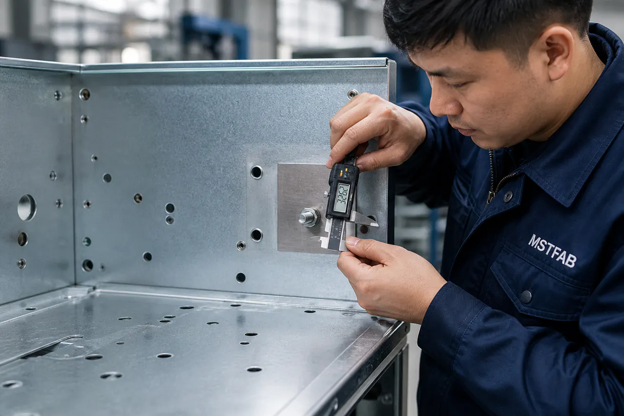
Where grounding and EMC interfaces can drift
Most failures are not dramatic. A stud moves a few millimeters, a masked pad becomes smaller after finishing, or a door return twists after welding. Each detail can be perfectly understandable in isolation and still stop downstream assembly.
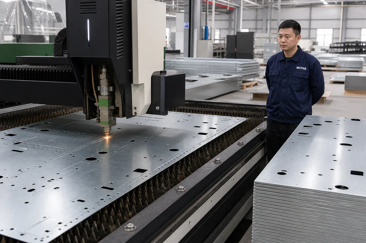
Laser cutting: locate the interface
Reference stud holes, connector openings and contact zones from stable functional datums. A cosmetic door gap should not locate the protective-earth stud.

CNC bending: protect the contact land
Door returns and frame flanges need realistic bend radii, tooling access and a sequence that preserves the buyer-defined mating geometry.
Buyer pain in plain language: a perfect flat blank can become an imperfect enclosure after bending and welding. Inspect the feature after the process that can move it.
A welded stud is a mechanical feature with electrical consequences
Provide the approved stud type, thread, material, finish, coordinates, weld method and required surrounding clearance. Also show the cable-lug and tool envelope when access is tight.
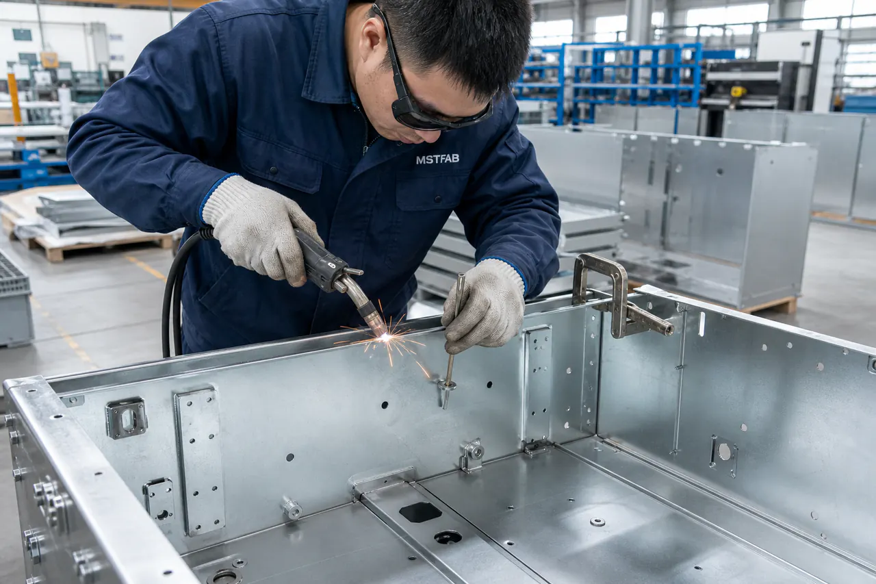
Welding can move the stud or distort thin sheet. The sensible CTQ is normally the stud location and surrounding shell geometry after welding, not only the laser-cut pilot hole before heat arrives.
MSTFAB can install the drawing-defined hardware and inspect its position. We do not choose the protective conductor or declare the final bonding path compliant.
Galvanized steel is conductive. The assembled enclosure is not automatically an EMC shield.

EMC performance depends on the complete design: apertures, seam continuity, door contact, penetrations, cable treatment, hardware and the electronics inside. The sheet material is only one input.
For the metal shell, useful DFM questions include whether the door return is straight, the frame land is continuous, the contact area remains accessible and welding has distorted the opening.
The OEM selects any conductive gasket or finger stock and defines compression or contact requirements. MSTFAB fabricates the approved geometry around it.
Keep chemistry evidence separate from electrical performance
RoHS restricts specified hazardous substances in covered electrical and electronic equipment. It does not certify a grounding stud, prove low contact resistance or demonstrate EMC performance.
For a galvanized shell, the purchasing package may need to identify the base material, zinc-coated route, passivation or conversion process, secondary finish, purchased hardware and supplier evidence. The responsible OEM determines how that evidence fits the finished product’s RoHS assessment.
A bare or masked contact zone also needs a controlled finished condition. State its dimensions, location, acceptable surface condition and protection during processing. Do not leave the finishing team to guess which shiny rectangle is electrically important.
For the wider documentation workflow, see the RoHS galvanized distribution box shell sourcing guide.
A trust table that connects claims to the actual empty shell
| Buyer check | Evidence to request | What it protects | Responsibility boundary |
|---|---|---|---|
| Drawing control | Part number, STEP, PDF and matching revision | Studs, cutouts and contact zones are built to one released baseline | Buyer releases; MSTFAB manufactures |
| Material and finish | Specified galvanized route and agreed supplier records | Prevents silent material or surface-process substitution | Buyer approves; MSTFAB controls purchased input |
| Laser cutting | Functional datum and cutout report where required | Protects grounding and mounting-hole position | MSTFAB mechanical scope |
| Welding | Fixture, weld sequence and post-weld dimensional checks | Protects stud location, frame squareness and door fit | MSTFAB mechanical scope |
| Finished FAI | Agreed CTQ report using the released revision | Catches coating, masking and final-geometry problems | MSTFAB measures agreed features |
| Electrical and EMC validation | OEM-approved test plan for the complete assembly | Confirms the finished product performs as intended | Buyer or qualified integrator |
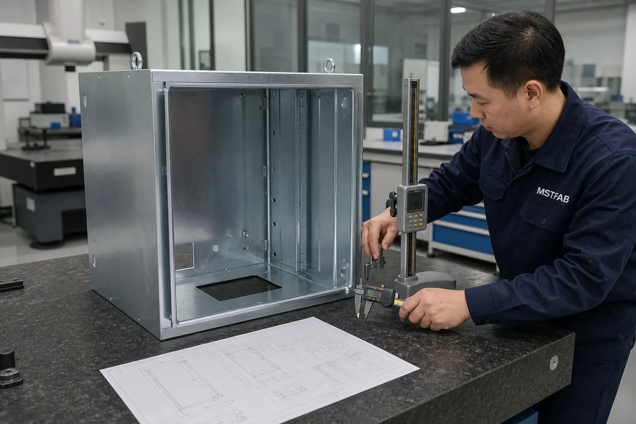
What MSTFAB actually does on this project
The production route follows the released drawing. Typical operations include DFM review, CNC laser cutting, CNC bending, hardware installation, sheet metal welding, specified finishing, dimensional inspection and export packaging.
We do not supply breakers, terminals, busbars, cable assemblies, electronic devices, wiring, programming or a finished distribution panel. There is no hidden electrical department behind the press brake.
Send enough information to price the real job
- STEP/STP assembly and controlled PDF
- Part number and revision
- Galvanized material route and thickness
- Finish and surface-process specification
- Grounding-stud type and coordinates
- Contact-zone size and masking boundary
- Door and frame contact geometry
- Buyer-selected hardware envelopes
- Weld and reinforcement callouts
- Critical-to-quality characteristics
- Mechanical FAI format
- Material or RoHS evidence required
- Prototype and production quantities
- Change-notification requirements
- Export packing requirements
Questions buyers ask before the PO
Does a galvanized steel box automatically provide protective grounding?
No. The metal shell can include buyer-defined studs and contact zones, but the OEM or integrator must design and validate the protective bonding path for the complete equipment.
Does galvanized steel automatically make the enclosure an EMC shield?
No. EMC performance depends on the complete assembly, including seams, doors, apertures, penetrations, cables, contact hardware and installed electronics.
Can MSTFAB weld grounding studs into the shell?
Yes. We can install drawing-defined welded studs, weld nuts, brackets and reinforcement, then inspect agreed mechanical characteristics after welding.
Should a bonding pad remain bare after finishing?
Only when the buyer-approved drawing requires it. Define the location, size, finished surface condition and protection method instead of relying on a workshop note.
Does RoHS prove grounding or EMC performance?
No. RoHS concerns restricted-substance obligations for covered electrical and electronic equipment. It does not validate electrical continuity or electromagnetic compatibility.
Does MSTFAB supply the complete electrical distribution box?
No. MSTFAB fabricates the empty sheet metal body, door, panels, brackets and mechanical interfaces. The buyer supplies and validates all electrical internals.
Primary references behind this guide
EU RoHS Directive
The official legal text defines restricted-substance obligations for covered electrical and electronic equipment. Read the directive.
IEC TR 61000-5-2
IEC installation and mitigation guidance covers earthing and cabling practices aimed at EMC. View the IEC reference.
IEC 60364-5-54
IEC guidance covers earthing arrangements and protective conductors for electrical installations. View the IEC reference.
Send the shell drawing, not just the compliance nouns
Share the STEP model, controlled PDF, galvanized material specification, grounding-stud details, contact zones, CTQs, quantities and mechanical FAI requirements. MSTFAB will review the metalwork from laser cutting through welding and finished inspection.
 WeChat Contact
 WhatsApp Me Directly