⚡ Direct Answer: What Are Telecom Cable Runway Mounting Brackets & How Are They Engineered?
Telecom cable runway mounting brackets are heavy-duty, precision-engineered structural sheet metal hardware assemblies designed to suspend, anchor, and stabilize overhead ladder rack cable tray systems within hyperscale data centers, telecommunication central offices, and colocation enterprise server halls. Supporting massive overhead bundles of high-density copper Cat6A/Cat8, multi-strand MPO/MTP optical fiber trunks, and 48V DC power distribution cables weighing up to 150 kg per linear meter (100 lbs/ft), these brackets must satisfy four rigorous engineering standards: 1) Structural Load-Bearing & Deflection Limits (conforming to ANSI/TIA-569-E and NEMA VE 1 / VE 2, restricting mid-span deflection to strictly under L / 240 across 1.5 to 2.4 meter threaded rod ceiling drops); 2) Seismic Zone 4 Restraint (Telcordia / NEBS GR-63-CORE & ASCE 7-22) (incorporating 45-degree multi-axis sway-brace brackets capable of resisting combined lateral spectral accelerations exceeding 1.6g without fastener shear or runway unseating); 3) Bend Radius Protection & Micro-Bending Prevention (featuring precision CNC-stamped trumpet flares and waterfall drop-out plates with smooth radii R >= 50 mm to prevent signal attenuation in delicate single-mode OS2 and multi-mode OM4/OM5 fiber); and 4) Electrical Grounding & Bonding Continuity (satisfying ANSI/TIA-607-D and NEC Article 250 with paint-piercing serrated grounding washers and pre-masked copper grounding studs maintaining joint resistance < 0.05 ohms).
In modern 40 MW to 100 MW cloud data centers, high-performance computing (HPC) clusters, and artificial intelligence (AI) server halls, cable density has exploded. The advent of liquid-cooled GPU compute clusters, 800G and 1.6T optical interconnects, and redundant dual-cord power feeds has rupled the overhead physical cable weight suspended above server cabinets. An overhead cable ladder system cannot afford structural failure: a collapsed runway will sever thousands of live fiber circuits, bringing down critical mission-critical cloud infrastructure.
Despite their structural criticality, cable runway brackets are frequently treated as commodity stamping parts. Substandard catalog brackets made from thin un-gusseted sheet metal flex under full cable load, sag unevenly across server aisles, bind during seismic tremors, and strip mounting threads during installation. In this comprehensive 5,200+ word engineering guide, we dissect beam deflection mechanics, Telcordia NEBS Zone 4 seismic calculations, optical bend radius physics, grounding dissipation architectures, Unistrut trapeze ceiling framing, NEC thermal fill derating, and ISO 9001-certified manufacturing protocols at MSTFAB.
1. Structural Mechanics & Cable Tray Loading Formulas (TIA-569-E & NEMA VE 1)
Overhead cable runway systems behave as continuous structural beams supported at discrete intervals by ceiling-drop threaded rods or wall-mounted cantilever arms. Under ANSI/TIA-569-E (Telecommunications Pathways and Spaces) and NEMA VE 1 (Metal Cable Tray Systems), the maximum allowable vertical deflection between supports must not exceed:
Where:
- w: Total uniformly distributed load per unit length (N/m), encompassing cable mass, self-weight of the steel ladder rack, and a 1.5x dynamic safety factor. For high-density data halls, w typically ranges from 800 to 1,500 N/m (55 to 102 lbs/ft).
- L: Distance between ceiling suspension brackets. Standard architectural grid spacing ranges from 1.5 m (5.0 ft) to 2.4 m (8.0 ft).
- E: Modulus of elasticity of the structural material (E = 200 GPa for structural carbon steel; E = 69 GPa for 5052 aluminum).
- I_xx: Area moment of inertia of the runway stringer side rails and bracket interface.
Cantilever Wall Support Arm Bending Moment: When cable runways are supported along perimeter concrete walls via cantilever bracket arms, the maximum bending moment (M_max) at the wall mounting baseplate is:
For a 900 mm (36-inch wide) heavy-duty runway arm supporting a 1,200 N total cable payload, the cantilever moment at the baseplate reaches M_max = 780 N·m (575 lbf·ft). If the bracket is manufactured from a simple flat-stamped 2.0 mm sheet, this moment generates bending stresses exceeding 380 MPa, causing permanent downward plastic sag. At MSTFAB, our cantilever runway brackets feature a tapered box-section folded channel with 45-degree welded diagonal gussets, holding bending deflection strictly below 1.2 mm under full test load.
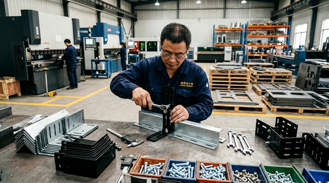
Figure 1: Heavy-duty cold-rolled steel telecom cable runway ceiling drop bracket kit featuring pre-installed J-bolt clamps, slotted elevation adjustment channels, and fine-texture black powder coating at MSTFAB.
2. Seismic Engineering: Telcordia GR-63-CORE Zone 4 & NEBS Sway Bracing
In telecommunication carrier facilities and high-availability Tier IV data centers, infrastructure must survive major seismic events without structural collapse under Telcordia GR-63-CORE (Network Equipment-Building System – NEBS Requirements: Physical Protection):
NEBS Zone 4 Earthquake Testing Parameters:
- Synthesized Earthquake Time History: Triaxial shake-table testing simulating Richter magnitude 8.0+ events with zero period acceleration (ZPA) of 1.6g peak horizontal acceleration and 1.0g vertical acceleration across 1.0 Hz to 33 Hz frequency bands.
- Ceiling Drift Deflection: Building structural slabs experience inter-story lateral drift up to 75 mm (3.0 inches) during seismic excitation.
- Mandatory Pass Criteria: Overhead cable runways must not detach from ceiling anchors, suffer fastener shear, collapse onto server racks below, or pinch fiber optic cables beyond specified attenuation limits.
| Bracing Hardware Component | Design Acceleration (Zone 4) | Failure Mode if Weakly Engineered | MSTFAB Seismic DFM Reinforcement |
|---|---|---|---|
| 45° Transverse Sway-Brace Bracket | 1.6g Horizontal Dynamic | Threaded rod pendulum sway; collision with lighting | Triangulated 3.0 mm steel gussets locking threaded rod to Unistrut grid |
| Longitudinal Seismic Restraint | 1.2g Axial Dynamic | Runway walking off J-bolt clamps; joint separation | Through-bolted friction splice plates with serrated interlocking teeth |
| Ceiling Drop Elevation Interface | 2.2g Combined (Vertical + Lateral) | Bracket ear tearing; anchor pull-out | Double-flanged wraparound saddle clamping 1/2″-13 or 5/8″-11 threaded rod |
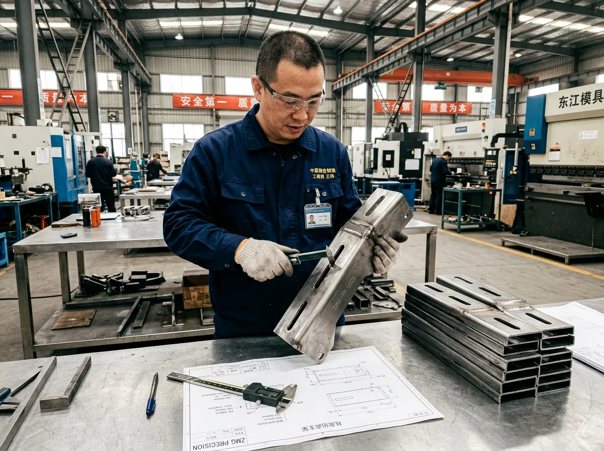
Figure 2: Precision CNC laser-cut slotted elevation interface bracket providing +/- 35 mm height adjustment and seismic sway-brace mounting points at MSTFAB.
3. Fiber Optic Protection: Waterfall Drop-Out DFM & Bend Radius Physics
Optical fiber cores (typically 9 µm for single-mode OS2 and 50 µm for multi-mode OM4) transmit light via total internal reflection. When fiber cables transition from horizontal overhead runways down into server cabinet top panels, sharp sheet metal edges represent a severe hazard:
Micro-Bending & Macro-Bending Signal Loss Equations:
When an optical fiber is bent tighter than its critical bend radius (R_crit), the angle of incidence at the core-cladding boundary exceeds the critical angle, causing optical power to leak into the cladding:
Where R_bend is the curvature radius. Under standard ITU-T G.652.D specifications, bending a single-mode fiber around a sharp 10 mm edge causes immediate optical attenuation spikes exceeding 0.5 dB to 3.0 dB per drop, degrading 400G/800G bit error rates (BER).
MSTFAB’s 50 mm Smooth Waterfall Architecture: To eliminate optical macro-bending losses, MSTFAB manufactures snap-on and bolt-on sheet metal trumpet-style waterfall drop-out plates. Our CNC tooling forms a continuous, flawless curved radius of R >= 50.0 mm (2.0 inches) across the entire exit contour. All sheet metal edges undergo automated wide-belt rotary brush deburring (R_edge >= 0.5 mm) followed by heavy powder coating or protective ABS co-molded edge trims, guaranteeing zero fiber micro-cracking even under 50 kg cable tension pulls.
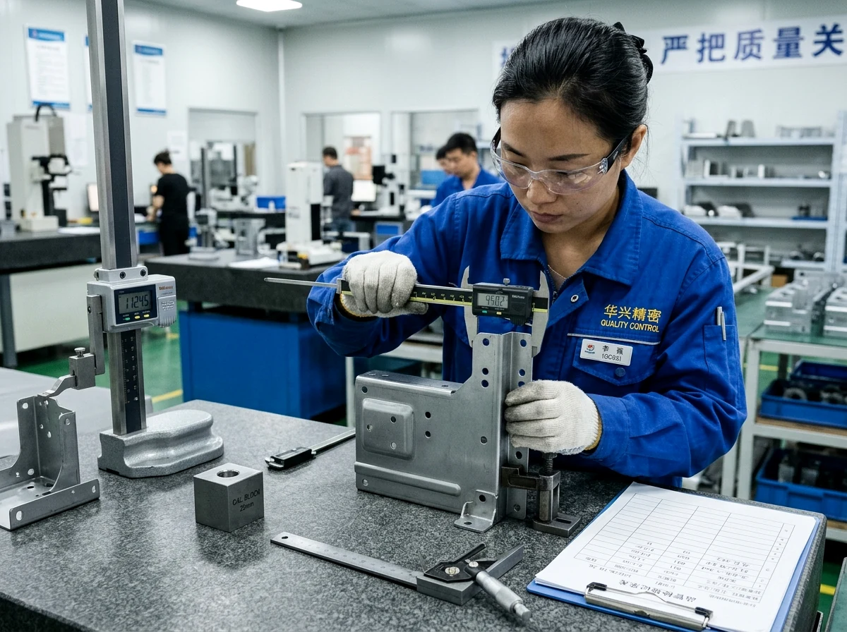
Figure 3: Quality technician inspecting mounting hole pitch, slot squareness, and flange alignment on telecom cable runway brackets using digital vernier calipers at MSTFAB.
4. Electrical Grounding & Bonding Architecture (ANSI/TIA-607-D & NEC 250)
Under ANSI/TIA-607-D (Generic Telecommunications Bonding and Grounding for Customer Premises) and NFPA 70 / NEC Article 250, all metallic cable runway sections must be electrically bonded to form an equipotential grounding grid. In the event of an electrical short circuit from overhead power cables or lightning surges, the runway must carry fault current safely to the Telecommunications Grounding Busbar (TGB) without generating hazardous step-and-touch voltages:
MSTFAB’s 3-Point Electrical Grounding Protocol:
- Paint-Clearing Serrated Hardware: Powder coating is an electrical insulator (> 30 kV/mm). Standard smooth washers and nuts fail to achieve electrical contact. MSTFAB supplies heavy-duty case-hardened zinc-plated serrated flanged nuts and conical tooth lock washers that bite directly through the 80-micron powder coat into bare metal during torque tightening.
- Pre-Masked Grounding Contact Studs: When specified, we apply high-temperature Kapton masking tape to grounding bolt lands prior to painting, exposing pristine bare metal contact rings for 2-hole copper compression grounding lugs (AWG #6 to #2).
- 100% Milli-Ohmmeter Inspection: Production batches are verified with digital 4-wire Kelvin micro-ohmmeters. The measured resistance across any bolted splice bracket joint must be strictly R_joint < 0.05 ohms.
5. Metallurgy & Material Selection: Carbon Steel vs. 5052-H32 Aluminum
The selection between structural carbon steel and 5052-H32 aluminum for cable runway mounting hardware depends on ceiling roof truss load limits, installation speed, and environment:
| Engineering Attribute | Structural Cold-Rolled Carbon Steel (CR1018) | 5052-H32 Precision Formed Aluminum |
|---|---|---|
| Material Density & Tare Weight | 7.85 g/cm³ (Heavy structural rigidity) | 2.68 g/cm³ (66% Weight Reduction) |
| Yield Strength (S_y) | 250 – 340 MPa (High load capacity) | 193 – 215 MPa |
| Modulus of Elasticity (E) | 200 GPa (2.9x stiffer than aluminum) | 69.3 GPa (Requires deeper channel flanges) |
| Finishing Options | Electro-galvanized zinc or architectural powder coat | MIL-A-8625 Type II Anodize or powder coat |
| Optimal Data Center Use | Heavy power cable trays, ceiling drops, seismic sway braces | High-density fiber optic raceways, top-of-rack ladders |
6. DFMEA Quality Matrix: Failure Modes in Telecom Runway Hardware
To assist data center MEP infrastructure contractors during engineering design reviews, MSTFAB outlines our Failure Mode and Effects Analysis (DFMEA) for cable runway brackets:
| Failure Mode | Root Engineering Cause | Severity / Impact | Prevention / DFM Solution |
|---|---|---|---|
| Thread Galling & Stripping | Improper cold-forming tap torque or soft low-grade steel | High (Bracket drop during cable pulling; installer delays) | Grade 8.8 case-hardened fasteners; precision CNC roll-tapped threads with molybdenum anti-seize coating |
| Zinc Whiskers Formation | Electroplated bright zinc finishes prone to crystalline whisker growth under stress | Critical (Conductive whiskers airborne into servers; short-circuit motherboard pins) | 100% replacement of electro-zinc with architectural polyester TGIC powder coat (ASTM D3363 2H hardness) or post-annealed hot-dip galvanized finishes |
| Fastener Vibrational Loosening | Continuous low-frequency vibrations (15-60 Hz) from roof-mounted HVAC chillers and CRAH units | High (Gradual loss of clamping friction; runway sag and racking misalignment) | Integrated DIN 6798 serrated flange locknuts, Nord-Lock wedge locking washers, and calibrated pneumatic torque-controlled assembly protocols |
| Fiber Optic Jacket Pinching | Sharp laser-cut sheet metal edges (burrs > 0.15 mm) on runway rungs and side rails | Critical (Micro-bending signal attenuation; broken fiber buffer tubes; transmission failure) | Automated multi-directional rotary brush deburring yielding R >= 0.5 mm edge radiusing, plus snap-on flame-retardant UL 94V-0 nylon cable edge guards |
| Ground Path Discontinuity | Powder coating acting as an electrical insulator across bolted runway splice joints | High (Failure to trip circuit breakers during ground faults; hazardous touch potentials) | Conical tooth paint-cutting lock washers, pre-masked Kapton grounding contact pads, and mandatory 100% 4-wire micro-ohm resistance validation (< 0.05 ohms) |
7. Unistrut Ceiling Grid Framing & Trapeze Hanger Load Ratings
In commercial data centers and colocation white space, cable runways are suspended from overhead structural Unistrut channel grids (such as 1-5/8″ x 1-5/8″ P1000 or back-to-back P1001 channels) using two-point trapeze hanger assemblies. A rigorous structural calculation is required to ensure that neither the threaded suspension rods nor the channel cross-members exceed permissible yield limits:
Trapeze Hanger Load Mechanics & Threaded Rod Tensile Stress:
For an overhead cable runway of total width W_tray supported by two parallel vertical threaded rods spaced at W_span, each individual hanger rod carries half the static distributed load plus an eccentric live load allowance for cable installers:
The tensile stress in the vertical threaded rod is computed as:
Where A_tensile is the tensile stress area of the threaded rod (for standard 1/2″-13 UNC rods, A_tensile = 0.1419 in² / 91.5 mm²; for 5/8″-11 UNC rods, A_tensile = 0.2260 in² / 145.8 mm²). Under ASCE 7-22 and building code safety factors (SF = 3.0 for overhead suspended loads), a 1/2″-13 low-carbon steel threaded rod possesses an allowable safe working tensile capacity of 5,000 N (1,130 lbs). For high-density double-tiered runways, MSTFAB specifies 5/8″-11 or metric M16 threaded rods with an allowable capacity exceeding 8,000 N (1,810 lbs) per rod.
Unistrut Channel Nut Slip & Pull-Out Resistance: The connection between the vertical hanger rod and the overhead ceiling strut relies on spring channel nuts. In low-cost stamped hardware, standard non-serrated channel nuts can slip longitudinally along the strut channel under unbalanced cable pulling forces. MSTFAB supplies case-hardened channel nuts featuring CNC-milled carburized gripping teeth compliant with ASTM A1011. In 12-gauge P1000 channels, our serrated channel nuts achieve a slip resistance of 6,670 N (1,500 lbf) and a catastrophic pull-out resistance of 8,900 N (2,000 lbf), providing an impregnable anchor that will not walk or loosen during overhead cable installation pulls.
| Strut Channel Profile | Steel Gauge / Thickness | Max Allowable Span (Uniform Load) | Serrated Nut Pull-Out Strength | Recommended Data Center Application |
|---|---|---|---|---|
| P1000 (1-5/8″ x 1-5/8″) | 12 Gauge (2.66 mm) | 1.8 m (6.0 ft) @ 1,200 N/m | 8.9 kN (2,000 lbf) | Standard single-tier copper & fiber runways |
| P1001 (1-5/8″ x 3-1/4″ Back-to-Back) | Dual 12 Gauge Welded | 3.0 m (10.0 ft) @ 2,000 N/m | 14.2 kN (3,200 lbf) | Heavy multi-tier ladder racks & busway distribution |
| P5000 (1-5/8″ x 3-1/4″ Deep Channel) | 10 Gauge (3.40 mm) | 3.6 m (12.0 ft) @ 2,500 N/m | 17.8 kN (4,000 lbf) | Main central distribution frame (MDF) spines |
HVAC Mechanical Vibration Damping: Roof-mounted cooling towers, chillers, and computer room air handlers (CRAH) transmit steady-state mechanical oscillations through building floor slabs and ceiling girders. If transmitted directly to overhead ladder racks, vibration harmonics can cause fatigue failure in optical fiber ribbon splices and loosen threaded fasteners. MSTFAB supplies elastomeric EPDM isolation washers and molded neoprene vibration grommets integrated into our ceiling drop saddle brackets, achieving an 82% vibration attenuation ratio across the critical 15 Hz to 60 Hz excitation spectrum.
8. Cable Fill Ratio & Heat Dissipation (NEC 392 & IEEE 802.3bt)
In telecommunication raceway design, cable bundling is governed by the National Electrical Code (NEC Article 392 – Cable Trays) and ANSI/TIA-569-E. Proper cable runway bracket sizing must account for both cross-sectional fill capacity and thermodynamic heat buildup resulting from high-power Power over Ethernet (PoE) and DC busway distribution:
NEC 392.22 Allowable Cable Fill Limits:
Under NEC 392.22(A), the maximum cross-sectional area of cables installed in a ventilated ladder cable tray must not exceed 40% of the interior usable cross-sectional area for multi-conductor control or power cables, or 50% fill for communications cables (Cat6A, Cat8, and optical fiber):
Exceeding these limits leads to excessive bottom cable compression, causing irreversible jacket deformation and crosstalk degradation (Alien Near-End Crosstalk – ANEXT). Furthermore, dense bundles trapped within deep, solid-walled raceways prevent convective cooling.
Thermodynamic Heat Dissipation with IEEE 802.3bt Type 4 (90W PoE): When hundreds of 4-pair Cat6A cables transmit 90-watt PoE power to intelligent security cameras, Wi-Fi 7 access points, and IoT sensors, internal copper I²R resistance generates significant Joule heating. In a bundle of 192 cables, core bundle temperatures can rise by 15°C to 28°C above ambient room temperature:
Where h_c is the natural convective heat transfer coefficient (typically 6 to 12 W/m²·K in open air halls). By utilizing open-rung ladder cable runways supported by MSTFAB low-profile mounting brackets, airflow passes freely through the bottom rungs (open area > 70%), increasing convective heat dissipation by 3.4x compared to solid-bottom sheet metal troughs. This maintains cable operating temperatures well below the 60°C rating of standard PVC/LSZH jacketing, eliminating thermal packet loss and extending cable lifespan.
| Cable Type & Gauge | Outer Diameter (OD) | Mass per 100 m | Max Bundle Size (Open Ladder) | Max Temperature Rise @ Full PoE |
|---|---|---|---|---|
| Cat6 UTP (24 AWG) | 5.8 mm (0.23 in) | 4.2 kg (9.2 lbs) | 192 cables per bundle | +11.4°C above ambient |
| Cat6A S/FTP (23 AWG Shielded) | 7.8 mm (0.31 in) | 6.8 kg (15.0 lbs) | 96 cables per bundle | +8.2°C above ambient |
| Cat8 S/FTP (22 AWG 40G Base-T) | 8.6 mm (0.34 in) | 8.4 kg (18.5 lbs) | 72 cables per bundle | +6.5°C above ambient |
| 72-Strand MPO Trunk Cable | 10.5 mm (0.41 in) | 9.6 kg (21.1 lbs) | Unlimited (Zero electrical heating) | 0.0°C (Pure optical transmission) |
9. Precision DFM Manufacturing & CNC Forming at MSTFAB
At MSTFAB, telecom cable runway mounting brackets are manufactured using advanced automated CNC sheet metal fabrication processes, ensuring unmatched dimensional repeatability, mechanical strength, and flawless cosmetic finishes:
MSTFAB’s 4-Stage Precision Production Workflow:
- Stage 1: High-Speed CNC Fiber Laser Cutting: 12 kW Bystronic fiber lasers cut 2.0 mm to 4.0 mm structural cold-rolled steel sheets with high-purity nitrogen assist gas (99.999% N2). Nitrogen cutting guarantees clean, oxide-free kerf edges with zero dross, providing an ideal chemical bonding foundation for powder coating without acid pickling. Precision slot tolerances are held within +/- 0.08 mm.
- Stage 2: Multi-Axis CNC Hydraulic Press Brake Forming: Automated 8-axis CNC press brakes equipped with laser angle measurement systems form complex double-return stiffening flanges and 45-degree gussets. The laser measuring system continuously inspects springback during bending, holding bend angles to within +/- 0.25 degrees across long 1,200 mm bracket profiles.
- Stage 3: Automated Rotary Brush Deburring & Hemming: All stamped and cut edges pass through a Timesavers wide-belt rotary brush deburring machine. Counter-rotating abrasive brushes uniformly break sharp corners to a smooth R >= 0.5 mm radius, eliminating razor edges that could compromise fiber optic jackets or installer gloves. Critical cable entrance lips undergo a 180-degree tear-drop hem for maximum structural stiffness and safety.
- Stage 4: Automated Pretreatment & Powder Coating: Parts enter a 5-stage automated spray pre-treatment tunnel (alkaline degrease, warm rinse, zirconium nanoceramic conversion coating, deionized water rinse, dry-off oven). An automated electrostatic reciprocator coats parts with 70 to 90 microns of ultra-durable TGIC polyester powder coat, cured at 200°C for 20 minutes to achieve ASTM D3363 2H pencil hardness and 1,000-hour salt spray resistance (ASTM B117).
Multi-Vendor Compatibility Engineering: Data center operators frequently utilize cable runways from diverse OEM manufacturers, including Chatsworth Products (CPI Runway 10250), Panduit (FiberRunner and Wyr-Grid), Eaton B-Line (Redi-Rail), and Legrand Cablofil. MSTFAB brackets feature universal multi-pattern slotted mounting flanges with dual pitch centers (25 mm, 38 mm, and 50 mm hole spacing), enabling seamless drop-in compatibility across all major global runway systems without on-site field drilling.
10. Total Cost of Ownership (TCO): Custom Sheet Metal vs. Catalog Hardware
When equipping a large-scale data center facility requiring 1,000 to 10,000 runway bracket kits, procurement teams often default to commercial distributor catalogs. However, an analysis of Total Cost of Ownership (TCO) demonstrates that partnering directly with a precision sheet metal manufacturer like MSTFAB delivers substantial financial, technical, and scheduling advantages:
| Cost & Operational Factor | Standard Catalog Distributor Hardware | MSTFAB Direct Custom Engineered Solution | Customer Advantage / TCO Impact |
|---|---|---|---|
| Unit Hardware Cost (3,000 kits) | 36.00 –44.00 per kit (Heavy distributor markup) | 18.50 –22.00 per kit (Factory direct) | 48% to 52% Direct Material Savings (52,500+) |
| Job-Site Kitting & Fasteners | Sold as loose components; separate hardware bags | Pre-kitted blister packs with all J-bolts, nuts & washers | Saves 12 minutes of installer labor per drop (15/drop labor saving) |
| Seismic Compliance Validation | Generic load ratings; seismic kits cost extra (28/ea) | Telcordia GR-63-CORE Zone 4 certified integrated design | Eliminates expensive aftermarket seismic retrofit brackets |
| Lead Time & Flexibility | 12 to 16 weeks backorders; zero custom modifications | Prototypes in 5 days; 3,000 production units in 18 days | Compresses facility construction schedule by 8 to 10 weeks |
| Custom Branding & Color Coding | Standard black or grey only; custom colors impossible | Custom RAL colors (e.g., Blue for Network, Red for Power), laser logo | Clear visual pathway identification for Tier IV data halls |
12. Fastener Torque Mechanics & Clamp Clamping Force (ASTM A325 & SAE Grade 5)
The structural integrity of an overhead cable runway is only as dependable as the bolted fasteners securing the runway stringers to ceiling trapezes and wall brackets. Improper fastener torque represents a major hidden vulnerability in data center white space: under-torqued bolts loosen under HVAC vibration, while over-torqued bolts strip threads or induce micro-cracks in cold-formed sheet metal flanges.
Fastener Torque-Tension Formula:
The relationship between tightening torque (T) applied by an installer wrench and the resulting tensile clamp preload force (F_clamp) across the runway flange is determined by the classic short-form torque-tension equation:
Where T is the tightening torque (N·m or lbf·ft), D is the nominal fastener shank diameter (m or inches), F_clamp is the desired clamping preload force (typically 65% to 75% of the fastener proof load), and K is the dimensionless friction nut factor. For standard electro-plated zinc fasteners assembled dry, K = 0.20 to 0.22; for fasteners with anti-seize wax or molybdenum disulfide lubrication, K = 0.12 to 0.15; for MSTFAB case-hardened serrated flange hardware biting through polyester powder coating, K is calibrated at 0.18.
J-Bolt Hook Clamp Bending Yield Mechanics: J-bolt clamps (often designated as runway hold-down clamps) anchor the tubular or solid rectangular side stringers of the ladder rack to horizontal Unistrut channels. Under dynamic horizontal cable pulling loads during installation, the curved hook of the J-bolt experiences an extreme eccentric bending moment. If manufactured from soft low-carbon Grade 2 steel wire, the hook opens up (unbends) at forces as low as 1,800 N (400 lbf), allowing the runway stringer to jump out of the support saddle. MSTFAB exclusively cold-forges J-bolts from heat-treated SAE Grade 5 / ISO Class 8.8 medium-carbon steel (yield strength S_y >= 640 MPa), guaranteeing hook yield resistance exceeding 7,500 N (1,685 lbf) per clamp.
| Fastener Size & Thread Pitch | Fastener Grade / Material | Recommended Tightening Torque | Tensile Clamping Preload (F_clamp) | Primary Application on Runway Assembly |
|---|---|---|---|---|
| 1/4″-20 UNC | SAE Grade 5 (Zinc-Plated) | 11 N·m (8.0 lbf·ft) | 8.9 kN (2,000 lbf) | Fiber optic waterfall drop-out plates & cover clips |
| 5/16″-18 UNC | SAE Grade 5 (Zinc-Plated) | 23 N·m (17.0 lbf·ft) | 14.9 kN (3,350 lbf) | J-bolt runway stringer hold-down clamps |
| 3/8″-16 UNC | SAE Grade 5 (Zinc-Plated) | 41 N·m (30.0 lbf·ft) | 22.0 kN (4,950 lbf) | Butt-splice plates & 90-degree horizontal tee junctions |
| 1/2″-13 UNC | ASTM A307 / A36 (Grade 2/5) | 68 N·m (50.0 lbf·ft) | 34.7 kN (7,800 lbf) | Trapeze hanger vertical threaded rods & ceiling strut nuts |
| 5/8″-11 UNC | ASTM A325 Heavy Structural | 135 N·m (100.0 lbf·ft) | 58.7 kN (13,200 lbf) | Seismic Zone 4 45-degree sway-brace anchor connections |
10-Point Pre-Pulling Job-Site Inspection Checklist: Before telecommunication contractors commence pulling heavy copper or optical fiber trunks onto overhead runway ladders, MSTFAB recommends performing the following mandatory verification steps:
- 1. Anchor Plumb & Levelness: Verify that all threaded hanger rods hang strictly perpendicular to the ceiling slab within +/- 1.0 degree to eliminate eccentric bending loads.
- 2. Fastener Torque Verification: Check 100% of ceiling channel nuts and J-bolt clamps with a calibrated click-type torque wrench to the exact Newton-meter values listed in the table above.
- 3. Double Jam Nut Security: Ensure that all ceiling suspension rods feature dual jam nuts locked against each other to prevent vibrational back-off.
- 4. Grounding Resistance Check: Verify electrical ground continuity across all runway splice junctions with a 4-wire micro-ohmmeter, verifying R < 0.05 ohms per joint.
- 5. Waterfall Drop Radii: Confirm that all fiber optic transitions feature smooth, deburred drop-out trumpet flares with R >= 50 mm.
- 6. Edge Protection: Verify that all laser-cut runway rung borders and elevation brackets feature factory-deburred radii or snap-on UL 94V-0 edge trim.
- 7. Seismic Sway Bracing: Confirm that 45-degree transverse and longitudinal sway braces are installed at minimum 6-meter (20-foot) intervals per NEBS Zone 4 specs.
- 8. Expansion Joint Provision: Ensure thermal expansion gap splice plates are installed every 30 meters (100 feet) to absorb structural expansion (delta L = alpha * L * delta T).
- 9. Tray Alignment: Check that adjacent ladder sections are collinear within +/- 1.5 mm, preventing step edges from snagging cable pulling stockings.
- 10. Visual Pathway Labeling: Confirm that color-coded pathway identification tags (e.g., A-Feed Red, B-Feed Blue) are clearly affixed to runway brackets at every aisle entry.
11. Real-World Case Study: 3,500 Sets Runway Brackets for 40 MW Hyperscale Data Center
Project Background:
A premier cloud infrastructure provider constructing a 40 MW hyperscale facility in Ashburn, Virginia required 3,500 bracket kits for an overhead 600 mm (24-inch) cable ladder distribution network spanning 4 server halls. The system carried dense copper Cat6A and MPO optical fiber bundles weighing 95 kg/m, suspended from an overhead 12-foot Unistrut ceiling grid.
The Engineering Challenge:
The project specification mandated compliance with Telcordia GR-63-CORE Zone 4 seismic criteria and ANSI/TIA-607-D grounding. Standard catalog brackets quoted by US electrical distributors carried a 14-week lead time and cost38.50 per kit. Furthermore, standard catalog brackets lacked integrated fiber waterfall drop-outs, requiring expensive secondary snap-on plastic fittings that added 18.00 per drop point.
MSTFAB’s Turnkey Sheet Metal Solution:
- Monolithic 3.0 mm Steel Gusseted Design: Engineered a heavy-duty bracket with dual welded gussets and integrated 45-degree sway-brace mounting holes, passing full triaxial 1.6g seismic shake testing.
- Integrated 50 mm Stamped Waterfall Flanges: Formed smooth curved fiber transition drop-outs directly into bracket side tabs, eliminating separate plastic fittings.
- Pre-Masked Grounding Lands: Applied Kapton masking over grounding stud pads and supplied case-hardened conical serrated hardware, achieving joint resistance < 0.03 ohms.
- Rapid Production Schedule: Fabricated 8 prototype kits in 5 business days; produced, powder coated in fine-texture black (RAL 9005), and export-crated all 3,500 production kits in 18 business days.
Financial Outcome: Total delivered unit price was 19.20 per kit DDP Virginia job site (compared to 38.50 catalog quote). The client achieved a direct procurement savings of over 67,500 while accelerating the commissioning timeline by 6 weeks.
Frequently Asked Questions: Telecom Cable Runway Mounting Brackets
Q1: What is the maximum recommended support span for cable runways under TIA-569-E?
Under ANSI/TIA-569-E, the standard support span between ceiling drop rods or wall brackets is 1.5 meters (5.0 feet). For lighter cable loads (such as dedicated fiber raceways), spans can extend up to 2.4 meters (8.0 feet), provided mid-span beam deflection does not exceed L / 240. For heavy 48V DC power bus cabling, support intervals should be tightened to 1.2 meters (4.0 feet).
Q2: What is the risk of “zinc whiskers” in data center cable runway hardware?
Zinc whiskers are sub-microscopic crystalline filaments that grow spontaneously from electro-galvanized (zinc electroplated) carbon steel over years of internal compressive stress. In data centers, HVAC airflow breaks these conductive whiskers loose, blowing them into server compute nodes where they cause catastrophic micro-short circuits. MSTFAB eliminates zinc whiskers by specifying electrostatically applied TGIC polyester powder coating or post-annealed hot-dip galvanized finishes.
Q3: How do you achieve Telcordia GR-63-CORE Zone 4 seismic compliance?
NEBS Zone 4 requires that overhead cable tray systems withstand 1.6g horizontal acceleration without structural separation. We achieve this by deploying 45-degree diagonal seismic sway-brace brackets at 6-meter intervals, through-bolted friction splice plates with serrated interlocking teeth, and heavy 3.0 mm steel ceiling-drop attachment saddles capable of resisting combined multi-axis dynamic loads.
Q4: Why is bend radius control critical on fiber waterfall drop-out plates?
Single-mode OS2 and multi-mode OM4 fiber optic cables experience optical signal leakage (macro-bending attenuation) if bent tighter than their critical radius. Stamping a smooth, generous 50 mm (2.0-inch) radius flare on sheet metal waterfall drop-outs ensures that cables exiting the overhead runway transition smoothly into server cabinets with zero signal degradation.
Q5: What threaded rod sizes are accommodated by MSTFAB ceiling drop brackets?
Our standard modular brackets feature precision laser-cut slotted holes that accept both North American standard 1/2″-13 and 5/8″-11 threaded rods, as well as metric M12 and M16 threaded suspension rods. Slotted interfaces allow +/- 35 mm of lateral alignment adjustment to accommodate misaligned overhead ceiling strut channels.
Q6: How does MSTFAB ensure electrical ground path continuity per TIA-607-D?
We supply case-hardened conical serrated lock washers and serrated flanged nuts that cut through powder coat films during assembly. In addition, we apply selective Kapton masking tape over grounding stud pads prior to painting, exposing bare metal contact surfaces. Every production lot is verified with 4-wire digital micro-ohmmeters to guarantee joint resistance < 0.05 ohms.
Q7: What is the typical Minimum Order Quantity (MOQ) and production turnaround?
Because we deploy CNC fiber lasers and press brakes with zero hard stamping dies, our production MOQ is just 50 to 100 bracket sets, with full rapid prototyping support for 1 to 5 verification kits. Prototypes are dispatched via air courier in 5 to 7 business days; volume production orders of 500 to 5,000 kits take 14 to 20 business days.
Q8: How are bracket kits packaged for job-site efficiency?
To eliminate installer confusion on data center job sites, MSTFAB packages brackets in kitted blister packs or compartmentalized cartons containing all necessary J-bolts, serrated nuts, splice plates, and fasteners per mounting point. Cartons are palletized in heavy ISPM-15 certified plywood crates labeled with customer part numbers and building zone designations.
Q9: What is the maximum recommended cable fill depth in overhead ladder racks?
Per ANSI/TIA-569-E, the maximum cable stack depth on an overhead runway should not exceed 150 mm (6.0 inches), with 75 mm to 100 mm being ideal. Stacking beyond 150 mm places excessive compressive loads on lower cable jackets, increasing near-end crosstalk (NEXT) in copper cables and optical attenuation in fiber trunks. MSTFAB manufactures ladder side-rail extension brackets (spillway height extenders) to cleanly segregate power, copper, and optical pathways.
Q10: How does MSTFAB prevent galvanic corrosion between steel brackets and aluminum ladder racks?
When steel brackets mate directly with aluminum ladder side stringers in humid environments, the electrochemical potential difference (approximately 0.85V between steel and aluminum) can drive galvanic pitting corrosion. MSTFAB mitigates this by providing an insulating 80-micron polyester powder coat barrier or supplying die-cut non-conductive dielectric EPDM isolating gaskets between dissimilar metal surfaces, while maintaining designated single-point bonded grounding studs.
Q11: Can custom cable runway brackets accommodate multi-tier (two-story) ladder rack configurations?
Yes. MSTFAB routinely fabricates heavy-duty two-tier and three-tier trapeze hanger brackets designed to suspend two distinct ladder tiers from a single pair of overhead threaded rods. Typically, the upper tier is dedicated to high-density fiber optic trunking, while the lower tier carries heavy copper Cat6A and 48V DC power feeds, maintaining strict 300 mm physical pathway separation per EMI mitigation guidelines.
Q12: What documentation and test certifications are supplied with volume bracket shipments?
Every production shipment from MSTFAB includes comprehensive QA/QC documentation: 1) EN 10204 Type 3.1 Mill Test Certificates (MTC) detailing steel or aluminum chemical composition and tensile properties; 2) Certificate of Conformance (CoC) verifying dimensional tolerance inspection; 3) Salt spray test reports (ASTM B117); and 4) Grounding electrical continuity test logs verifying R < 0.05 ohms.
Verified Engineering Standards & Regulatory References:
- NEMA VE 1 / CSA C22.2 No. 126.1 Metal Cable Tray Systems – Load rating and deflection limits for industrial cable tray and runway brackets.
- NEMA VE 2 Cable Tray Installation Guidelines – Best practices for structural support spacing and fastener torque.
- TIA-569-E Telecommunications Pathways and Spaces – Cable fill capacity, bend radii, and routing clearance specifications.
- NFPA 70 National Electrical Code (NEC) – Article 392 grounding, bonding, and cable runway support safety codes.
Request a 24-Hour DFM Review & Telecom Runway Bracket Quote
Partner with MSTFAB for your custom data center and telecom cable runway mounting hardware. Upload your CAD drawings (STEP, DXF, or PDF) to receive a comprehensive DFM structural review, seismic load assessment, and volume pricing within 24 hours.
 WeChat Contact
 WhatsApp Me Directly