How do design engineers manage tolerance stack-up between 2D laser cutting and 3D CNC press brake bending?
Managing tolerance stack-up requires recognizing the fundamental accuracy disparity: 2D fiber laser cutting holds hole-to-hole pitch within ±0.05 mm, whereas 3D press brake air bending introduces ±0.25 mm flange length variance and ±0.3° to ±0.5° angular springback per bend. To prevent assembly binding, engineers must: (1) dimension all features baseline from functional datums rather than chain-dimensioning consecutive bends, (2) calibrate empirical K-factors to account for sheet thickness roll variations (±0.05 mm), (3) maintain hole-to-bend spacing ≥ 2.5t + r, and (4) incorporate slotted clearance holes (±1.0 mm) on mating brackets to absorb cumulative statistical stack-up.
1. The Precision Disparity: 2D Flat Laser vs. 3D Formed Reality
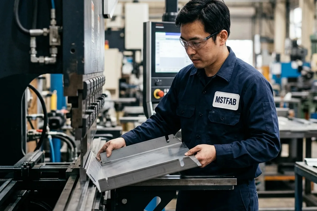
Modern 3D CAD modeling software treats sheet metal as a perfect, mathematically uniform solid. In CAD space, an enclosure door with five consecutive 90° bends drops effortlessly onto a cabinet frame with zero clearance issues. However, when transitioning to the factory floor, a profound precision gap emerges:
A CNC fiber laser cuts flat 2D profiles with extreme positioning accuracy—often achieving repeatability within ±0.03 mm to ±0.05 mm. But the instant that flat blank is placed between the punch and die of a CNC press brake, it enters the realm of plastic mechanical deformation. Material thickness tolerances, tensile strength variations between mill heats, grain direction orientation, tooling wear, and elastic springback compound at every single bend line.

2. The Physics of Tolerance Dispersion in Sheet Metal Forming
To design parts that assemble without reaming or forcing, engineers must understand the four primary sources of forming variance:

- Sheet Thickness Mill Variations: Commercial sheet metal standards (e.g., ASTM A568 / EN 10131) permit thickness variations of ±0.05 mm to ±0.10 mm across a single coil. Because bend deduction depends directly on material thickness, a sheet that is 0.08 mm thicker than nominal will bend tighter and produce longer flanges.
- Elastic Springback: When the press brake punch retracts, the bent sheet partially springs back (typically 1.5° to 2.5° for mild steel, and 3° to 6° for stainless steel). While CNC press brakes compensate by over-bending, slight variations in material yield strength cause angle variations of ±0.3° to ±0.5°. Across a 150 mm flange, an angular error of 0.5° translates to 1.3 mm of linear edge displacement.
- Rolling Grain Direction: Bending parallel to the sheet rolling direction produces lower bend resistance and higher springback than bending perpendicular (transverse) to the grain. In nested parts oriented at different angles on a laser cutting sheet, bend angles will vary unless compensated per part.
- Backgauge Positioning: The press brake backgauge stops against a physical sheet edge. If that edge was deburred aggressively or deformed by a previous bend, the backgauge datum shifts by ±0.10 mm.

3. Chain Dimensioning vs. Baseline Dimensioning
The single greatest drawing mistake committed by mechanical engineers is chain dimensioning (dimensioning feature B from feature A, feature C from feature B, and feature D from feature C across multiple formed flanges).
In a chain of four consecutive bends, each with an independent tolerance of ±0.25 mm, the worst-case arithmetic tolerance stack-up at the final flange reaches ±1.0 mm. Mounting holes placed on the first and last flanges will completely fail to align with a rigid mating frame.
The Baseline Solution: All critical functional features—especially mounting holes, connector cutouts, and mating datum surfaces—must be dimensioned from a single primary functional datum (such as the base mounting floor). By dimensioning baseline, the tolerance of any feature depends only on its direct distance to the datum, preventing compounding errors across intermediate bends.
4. Cutout Proximity to Bend Lines
When sheet metal bends around a die radius, the material inside the inner bend radius undergoes compressive strain, while the outer radius experiences severe tensile stretching. This plastic deformation zone extends outward from the bend tangent line by roughly 2.0 to 2.5 times the material thickness.
If a laser-cut hole or connector slot is positioned inside this deformation zone, the material flow pulls the hole out of round, bowing the edge into an egg shape and causing mounting fasteners to bind.
- Minimum Hole-to-Bend Rule: Maintain a minimum distance from the edge of any hole to the bend tangent line: d ≥ 2.5t + r.
- Relief Cutouts: If a cutout must extend through the bend line, design a rectangular or teardrop relief notch extending past the bend radius to isolate the cutout edge from plastic deformation.

5. Hardware Insertion, Welding & Finishing Compensation
Downstream assembly processes further alter finished part dimensions. Designers must account for secondary operations during the initial laser/bending layout:

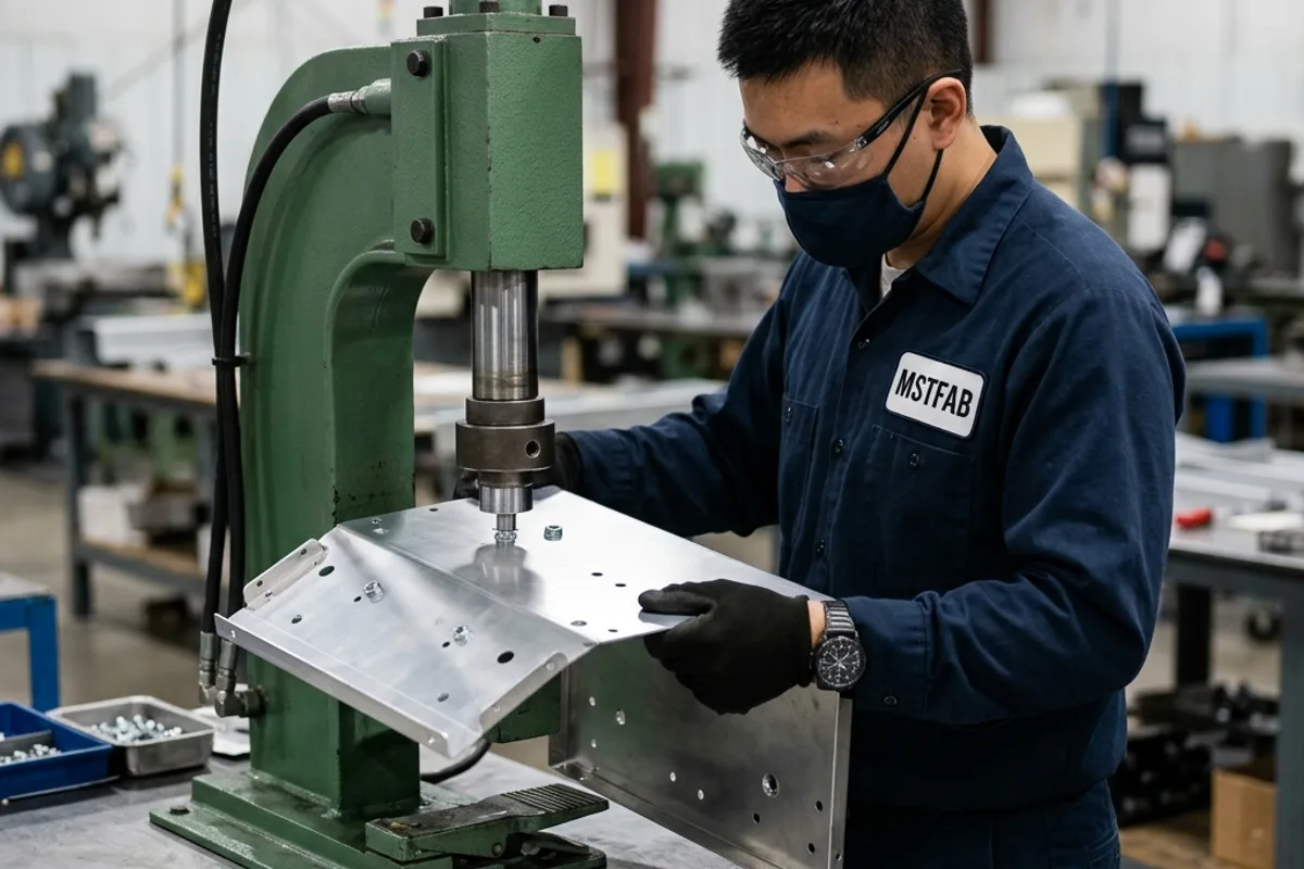
- Self-Clinching PEM Hardware: Pressing fasteners into flat blanks prior to bending provides full punch clearance. However, clinch nuts placed within 3.0× material thickness of a bend line will deform the hole or interfere with the V-die shoulder.
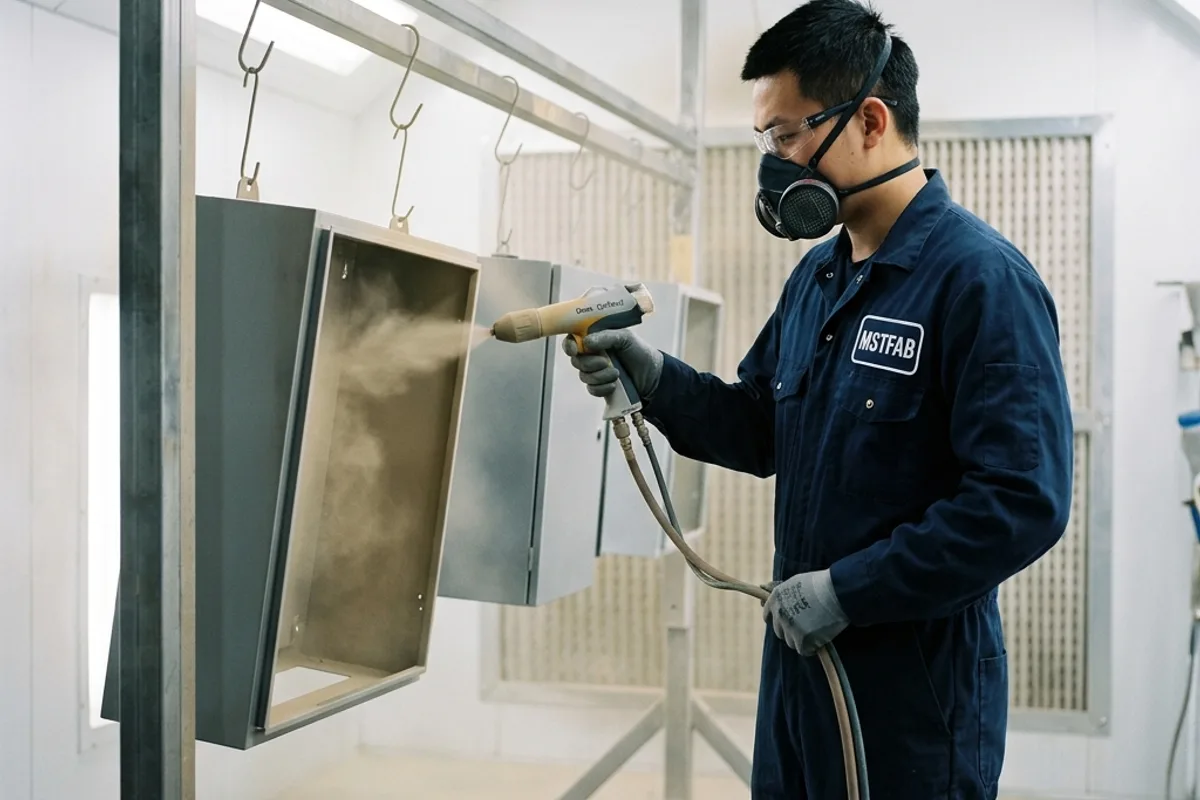
- Coating Thickness Allowance: Architectural powder coating adds 75 μm to 120 μm (0.075 mm to 0.12 mm) of dry film thickness to every surface. On slip-fit telescoping covers or hinge pins, uncompensated powder coat can consume the entire design clearance, resulting in severe binding.
6. Tolerance Stack-Up Standard Matrix & Mitigation Rules
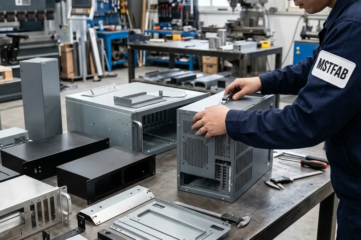
MSTFAB benchmarks manufacturing tolerances against international standards to ensure repeatable assembly:
| Feature Dimension | Manufacturing Stage | Standard Tolerance | Precision Tolerance (MSTFAB) | DFM Mitigation Strategy |
|---|---|---|---|---|
| Laser Cut Hole Pitch | 2D Flat Cutting | ±0.10 mm | ±0.05 mm | Keep on same plane; laser center-punch |
| Single Flange Length | 1-Bend Press Brake | ±0.35 mm | ±0.20 mm | Backgauge directly against formed edge |
| Bend Angle Accuracy | Press Brake Air Bend | ±0.75° | ±0.25° | Real-time laser angle tracking & dynamic crowning |
| Multi-Bend Envelope (3+ Bends) | Formed U-Channel | ±0.80 mm | ±0.40 mm | Baseline dimensioning from primary datum floor |
| Welded Frame Squareness | TIG / MIG Assembly | Δ ≤ 1.5 mm | Δ ≤ 0.5 mm | 3D modular fixture tables & tab-slot locators |
| Mating Fastener Alignment | Final Assembly | ±0.20 mm clearance | Slotted ±1.0 mm | Specify floating clinch nuts (PEM AC/AS) |
Eliminate Enclosure Tolerance Stack-Up Issues Today
MSTFAB bridges the gap between 2D laser cutting and 3D CNC press brake forming. Send us your CAD models for complete tolerance stack-up analysis, K-factor calibration, and precision prototype verification.
 WeChat Contact
 WhatsApp Me Directly