How do advanced sheet metal fabricators eliminate welding warpage and ensure squareness in heavy-duty welded frames?
Preventing welding warpage requires combining DFM self-fixturing tab-and-slot geometry (laser-cut to ±0.05 mm repeatability), rigid clamping on precision 3D modular welding tables, low-heat-input pulsed GMAW/FCAW welding, strictly balanced skip-welding sequences that equalize thermal contraction across neutral axes, post-weld hydraulic straightening or thermal flame stress relief, and final coordinate measuring machine (CMM) or 3D laser tracker inspection guaranteeing overall squareness and mounting pad coplanarity within ±0.5 mm over a 2000 mm span.
1. The Engineering Challenge: Welding Warpage in Welded Metal Frames
Heavy-duty sheet metal frames and tubular chassis serve as the structural skeletons for automation systems, semiconductor capital equipment, large medical imagers, battery energy storage systems (BESS), and outdoor power distribution skids. These frames must support heavy internal mechanical sub-assemblies while maintaining precise mounting coplanarity and diagonal squareness.
However, welding is an intensely localized thermal process. When molten weld metal cools from its solidification temperature (~1500° C for steel) to ambient temperature, it undergoes volumetric thermal shrinkage (~1.5% to 2.0%). Because the surrounding cooler metal resists this contraction, massive residual stresses develop—frequently exceeding the yield strength of the material. The result is angular distortion, longitudinal bow, and torsional twist that causes mounting bolt holes to misalign and enclosure doors to bind.
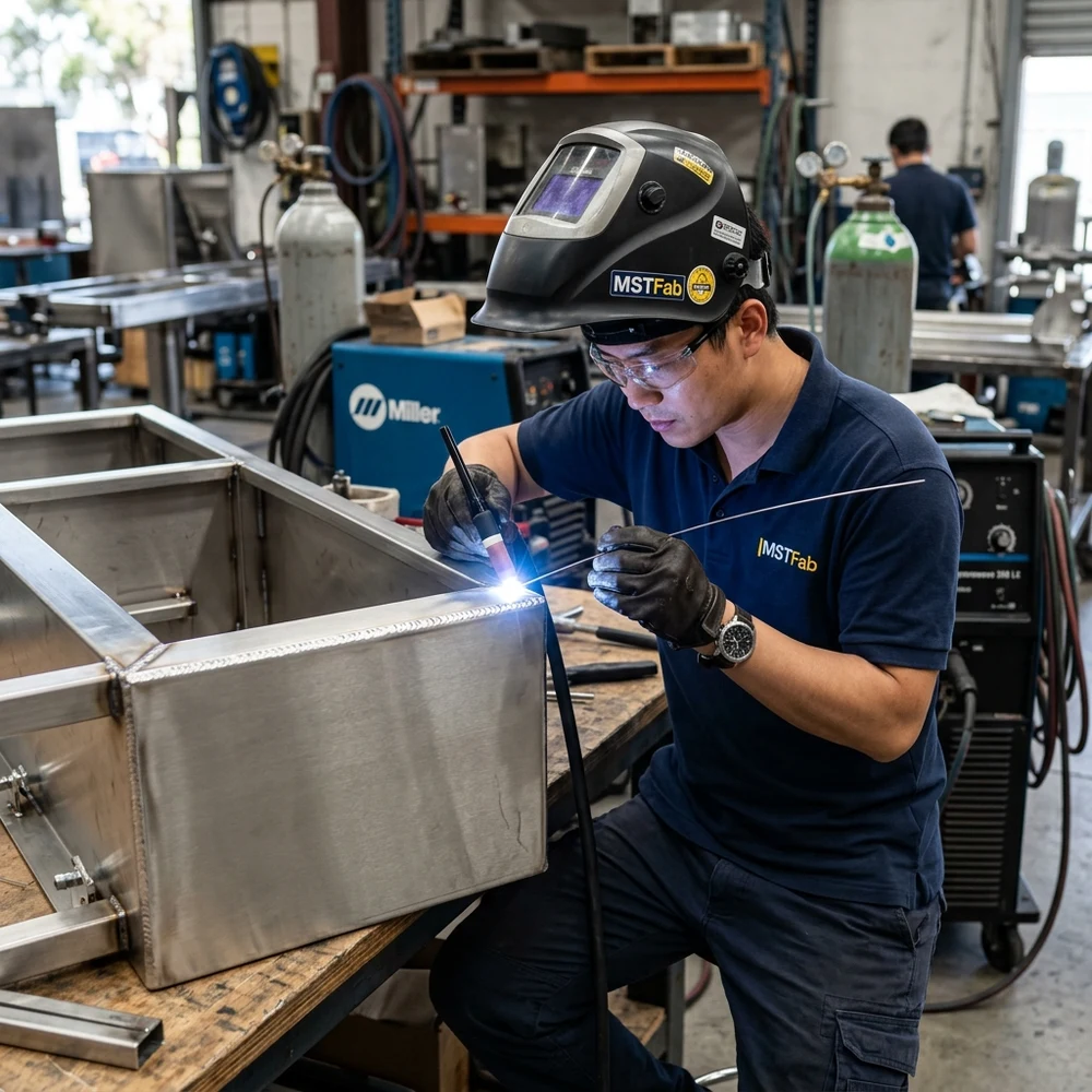
2. DFM for Distortion Control: Self-Fixturing Tab-and-Slot Geometry
The most effective strategy for preventing weld warpage occurs during the CAD design phase, before any metal is cut. Traditional frame manufacturing relied on manual tape measurement, loose butt joints, and heavy reliance on welder judgment—leading to cumulative tolerance stacking.
MSTFAB implements interlocking tab-and-slot architecture across custom frame weldments:
- Precision Laser-Cut Locating Tabs: Formed sheet metal channels and internal structural ribs are designed with laser-cut interlocking tabs and mating mortise slots held to ±0.05 mm positional tolerance.
- Self-Squaring Fit: Components snap together in three dimensions, enforcing mechanical squareness and establishing rigid datum references prior to arc strike. This eliminates human assembly error and slashes fit-up labor by up to 60%.
- Minimized Weld Volume: Designing tabs to carry primary mechanical shear loads allows weld sizes to be engineered down to the minimum necessary for structural retention. Smaller weld fillets introduce significantly less total heat input, reducing shrinkage forces proportionately.
3. Physics of Weld Shrinkage & Symmetrical Sequencing
Weld distortion manifests in three primary geometric modes: transverse shrinkage (contraction perpendicular to the weld seam), longitudinal shrinkage (contraction along the length of the weld), and angular distortion (unequal shrinkage between the weld face and root, pulling flanges out of square).
To counteract these contraction vectors, MSTFAB welders enforce strict sequencing rules:
- Balanced Symmetrical Welding: Welds are deposited symmetrically around the neutral axis of the frame profile. If a fillet weld is placed on the outer flange, an opposing weld must be deposited simultaneously or immediately afterward on the interior flange to neutralize bending moments.
- Back-Step & Skip Welding: Instead of depositing a single continuous 1000 mm weld bead from left to right, the weld is divided into short 100 mm segments welded in a back-step sequence (welding segment 2 back toward segment 1, segment 3 toward segment 2). This breaks up continuous longitudinal heat build-up and limits localized thermal expansion.
- Pre-Cambering / Intentional Preset: For frames known to bow in a specific direction under weld contraction, components are mechanically clamped with a deliberate reverse pre-camber (e.g., 2.0 mm reverse deflection). When the weld cools and contracts, it pulls the assembly back into nominal dead-flat alignment.
4. Precision Tooling: 3D Modular Clamping Fixtures
Welding heavy frames on flat concrete shop floors is a recipe for catastrophic warpage. MSTFAB utilizes precision Siegmund and Demmeler 3D modular welding fixture systems. These heavy cast-alloy/tool-steel tables feature precision CNC-drilled 28 mm bore grids on 100 mm centers, with surface flatness certified within ±0.05 mm over the entire table surface.
Frames are locked down using high-strength hydraulic and mechanical toggle clamps, rigid angle blocks, and eccentric datum stops. The frame remains clamped under rigid constraint during tacking, root pass welding, and final filler passes, and is allowed to cool below 100° C before clamp release. This rigid restraint forces the cooling weld metal to yield plastically, preventing elastic springback and structural warping.
5. Post-Weld Stress Relief & Precision Pad Machining
For ultra-critical machinery bases requiring sub-millimeter mounting coplanarity (e.g., linear guide rails, robotic transfer tracks, ballscrew bearing mounts), welding alone cannot guarantee sub-0.1 mm tolerances. MSTFAB provides two secondary operations to deliver extreme precision:
- Vibratory or Thermal Stress Relief: Welded frames are subjected to controlled furnace stress relief (heating to 580° C–620° C with controlled ramp and soak cycles) or sub-resonant vibratory stress relief (VSR). This relieves internal locked-in residual stresses without degrading material mechanical properties, preventing long-term dimensional drift during field operation.
- Post-Weld CNC Gantry Machining: Rather than attempting to maintain tight machining tolerances through the high heat of welding, thick mounting pads and datum bosses are welded in place with 2.0–3.0 mm of excess machining stock. After welding and stress relief, the entire frame is transferred to a 5-axis CNC gantry milling center. The machine faces all mounting pads and bores all locating dowel holes in a single setup, guaranteeing absolute coplanarity within ±0.05 mm across multi-meter spans.
6. Quality Inspection & Tolerancing Standard Matrix
Every fabricated frame undergoes comprehensive dimensional and structural verification against international standards:
| Geometric Parameter | Standard Specification | Inspection Equipment | MSTFAB Standard Tolerance |
|---|---|---|---|
| Overall Frame Length / Width | ISO 2768-m / ISO 13920 Class B | Laser rangefinder / calibrated steel tape | ±0.8 mm (up to 2000 mm span) |
| Diagonal Squareness | Corner-to-corner delta | Faro 3D Laser Tracker / Vernier trammels | Δ ≤ 1.0 mm across 2500 mm diagonal |
| Mounting Face Coplanarity (As-Welded) | Planar flatness deviation | Precision granite flat & feeler gauges | ≤ 0.8 mm over 1500 mm surface |
| Mounting Face Coplanarity (CNC Milled) | Post-machined datum planes | Portable CMM articulated arm / Dial indicator | ≤ 0.05 mm across all machined pads |
| Weld Joint Integrity | AWS D1.1 / ISO 5817 Level B | Visual (VT) + Magnetic Particle (MT) | 100% full fusion; zero cracks or lack of penetration |
| Paint / Coating Adhesion | ASTM D3359 Cross-Hatch / Positector | Coating thickness gauge & cross-cut tape test | 80–120 μm DFT; Class 5B zero detachment |
Tired of Welded Frames That Arrive Warped and Out of Square?
MSTFAB engineers precision welded frames utilizing tab-and-slot self-fixturing, heavy 3D modular clamping tables, AWS D1.1 certified robotic and manual welding, and post-weld CNC gantry machining. Guaranteed dead-flat mounting surfaces and flawless assembly fit.
 WeChat Contact
 WhatsApp Me Directly