⚡ Direct Answer: What Are BESS Enclosure Heater Mounting Brackets?
BESS enclosure heater mounting brackets are precision-engineered, heavy-duty structural sheet metal mounting assemblies designed to secure, position, and thermally decouple electric convection and positive temperature coefficient (PTC) fan heaters within utility-scale Battery Energy Storage System (BESS) containers and modular battery power cabinets. Manufactured from 2.0 mm to 3.0 mm heavy-gauge 304/316 stainless steel or Aluzinc (55% Al-Zn coated steel), these brackets serve 4 mission-critical engineering functions: 1) Thermal Isolation Standoff (maintaining a calibrated ≥25 mm conductive barrier to eliminate localized thermal hotspots on structural enclosure walls); 2) Radiant Baffle Shielding (redirecting high-temperature infrared radiation away from volatile lithium iron phosphate / NMC battery modules); 3) Seismic & Vibration Resistance (complying with IEEE 693 and Telcordia GR-63-CORE Zone 4 dynamic shock loads); and 4) Electrical Bonding Continuity (providing low-impedance <0.1 Ω grounding paths compliant with UL 508A and NFPA 855 fire safety standards).
Table of Contents: Engineering Sourcing & DFM Overview
- 1. The Critical Physics of Anti-Condensation Heating in Utility-Scale BESS
- 2. Psychrometric Dew Point Control & Thermal Calculations for Outdoor Containers
- 3. Mechanical Bracket Architectures: Cantilever, Straddle & Modular DIN Assemblies
- 4. Radiant Heat Shielding & Thermal Airflow Baffle DFM Principles
- 5. Material Selection Matrix: 304/316 Stainless Steel vs. Aluzinc vs. Heavy Aluminum
- 6. Seismic, Shock & Operational Vibration Engineering (IEEE 693 & IEC 60068)
- 7. Electrical Grounding, Equipotential Bonding & Hardware Insertion (UL 508A)
- 8. Precision Sheet Metal Fabrication Workflow: Laser Cutting, Forming & Welding
- 9. Thermal Interface Materials (TIM), Ceramic Washers & Vibration Isolators
- 10. Quality Metrology, CMM Inspection & AS9102 First Article Inspection (FAI)
- 11. OEM Procurement Checklist: Specifications to Include with BESS RFQs
- 12. Comprehensive Engineering FAQs on BESS Heater Mounting Brackets
1. The Critical Physics of Anti-Condensation Heating in Utility-Scale BESS
Utility-scale battery energy storage systems (BESS)—whether packaged in modular power enclosures or 20-foot / 40-foot ISO shipping containers—operate in hostile, non-conditioned outdoor environments ranging from sub-zero Canadian wind farms (-40° C) to scorching Arizona solar fields (+50° C). While liquid-cooling cold plates and high-capacity HVAC chillers manage high operational heat loads during heavy charging and discharging cycles, they are structurally incapable of managing low-temperature moisture condensation during standby periods.
When a BESS container sits idle overnight or during grid curtailment windows, the internal ambient air temperature drops rapidly. As the metallic container walls and structural steel frame cool below the ambient dew point, relative humidity (RH) inside the enclosure spikes toward 100%. Without dedicated, strategically positioned anti-condensation heaters mounted on rigid standoff brackets, microscopic moisture droplets condense across high-voltage busbars, battery management system (BMS) circuit boards, and inter-rack communication cabling.
The Catastrophic Failure Modes of BESS Internal Condensation
- Dielectric Breakdown & High-Voltage Arc Flash: Modern BESS DC bus architectures operate at 1,000V to 1,500V DC. Surface condensation across insulating supports reduces surface creepage distance, inducing tracking currents that trigger catastrophic catastrophic high-voltage phase-to-ground flashovers.
- Lithium Dendrite Growth & Internal Shorts: Moisture ingress around cell vent seals and BMS terminal connectors accelerates electrochemical galvanic corrosion, generating conductive metallic dendrites that can penetrate cell separators and initiate localized thermal runaway.
- False Flame/Gas Detector Alarms: Optical smoke detectors, off-gas sensors (detecting CO, H2, and VOCs), and aspirating smoke detection (ASD) sampling tubes trigger false emergency shutoffs and accidental aerosol fire suppressant discharge when condensation occludes optical sensing lenses.
- Galvanic Corrosion of Structural Enclosure Mounts: Moisture accumulation at the junction between steel chassis frames and zinc-plated brackets accelerates oxidation, weakening the mechanical integrity of the entire rack infrastructure over a 20-year asset lifecycle.

2. Psychrometric Dew Point Control & Thermal Calculations for Outdoor Containers
The primary thermal purpose of an enclosure heater is not to heat the entire container to human comfort levels, but to maintain the internal air and critical component surfaces at least 3° C to 5° C above the external dew point temperature at all times.
To achieve this without wasting parasitic grid power or overheating adjacent battery cells, thermal engineers must precisely calculate the required heating wattage and position the mounting brackets at optimal convective elevations.
Enclosure Anti-Condensation Heating Power Equation
The baseline heating power (Pheat in Watts) required to maintain temperature elevation in an outdoor IP55/NEMA 3R/4X enclosure is governed by steady-state heat loss through the container skin:
Where:
- A = Total exposed exterior surface area of the enclosure (m²).
- U = Overall thermal heat transfer coefficient of the insulated enclosure wall (W/m^2 · K). For standard 50 mm polyurethane foam-insulated sandwich walls, U ≈ 0.45 W/m^2 · K; for non-insulated steel sheet enclosures, U ≈ 5.5 W/m^2 · K.
- ΔT = Required differential temperature lift between interior air and minimum ambient design low (typically 5° C to 10° C above dew point).
- Pinternal = Parasitic standby heat dissipation generated by idle inverters, BMS controllers, and DC-DC converters (Watts). When the system is completely de-energized, Pinternal = 0.
| BESS Enclosure Format | Typical Volume & Capacity | Nominal Heater Sizing | Bracket Quantity & Configuration | Heater Technology Type |
|---|---|---|---|---|
| Modular Battery String Cabinet | 1.5 m³ – 3.0 m³ (100 kWh – 250 kWh) | 200W – 400W Total | 2 × Bottom-mounted cantilever offset brackets | PTC Ceramic Convection Elements |
| Outdoor Power Conversion Cabinet (PCS) | 2.5 m³ – 5.0 m³ (500 kW Inverter) | 400W – 800W Total | 2 × Heavy-duty DIN rail support straddles | Forced-Air Axial Fan Heaters |
| 20-Foot ISO Modular BESS Container | 30 m³ – 35 m³ (1.5 MWh – 2.5 MWh) | 2,000W – 4,000W Total | 6 to 8 × Floor-to-wall gusseted bracket assemblies | Multi-Stage Fan Heaters with Baffles |
| 40-Foot High-Cube BESS Container | 70 m³ – 76 m³ (3.5 MWh – 5.0 MWh) | 4,000W – 8,000W Total | 12 to 16 × Distributed perimeter bracket assemblies | Zone-Controlled Industrial Fan Heaters |
3. Mechanical Bracket Architectures: Cantilever, Straddle & Modular DIN Assemblies
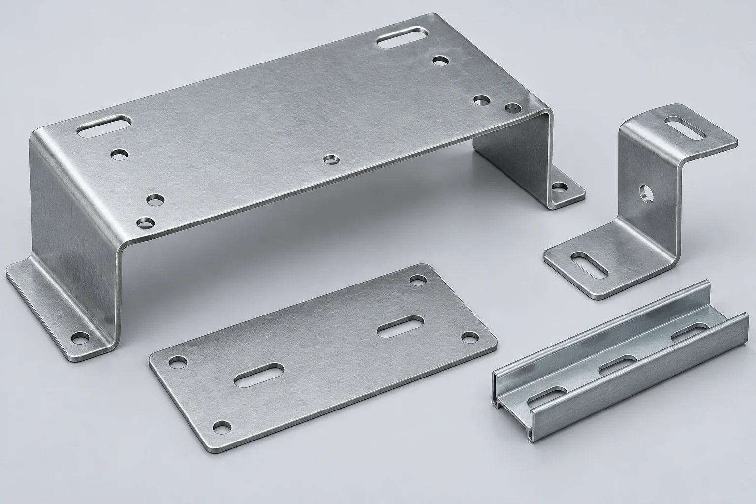
BESS enclosure heater mounting brackets must accommodate extreme weight-to-stiffness requirements, maintain tight spatial envelopes within densely packed battery corridors, and facilitate rapid field servicing. MSTFAB engineers and fabricates three primary mechanical configurations:
1. Z-Fold & U-Channel Cantilever Offset Brackets
Cantilever brackets mount directly to vertical structural uprights or unistrut channels. By utilizing CNC press brake air-bending with dual 90° joggle bends, the bracket offsets the heater 35 mm to 60 mm away from the mounting surface. This air gap prevents conduction into the container skin while establishing natural chimney convection currents beneath the heating element.
2. Dual-Flange Straddle Floor Mounts
In large walk-in containers, convection heaters are installed 150 mm to 200 mm above the false floor or sub-floor plenum. Straddle brackets utilize two symmetric laser-cut triangular side gussets tied together by a formed cross-plate. This bridge architecture supports heavy 5 kg+ industrial fan heaters under severe lateral seismic accelerations without cyclical fatigue.
3. Modular DIN Rail Adapter Brackets
For compact power conversion enclosures, heaters often mount onto standard 35 mm × 7.5 mm or 35 mm × 15 mm top-hat DIN rails (EN 50022). MSTFAB manufactures heavy-duty sheet metal DIN adapter brackets featuring integrated spring-steel latching clips and positive anti-slide stop tabs, ensuring heaters cannot migrate along the rail during road transport.
| Bracket Architecture | Standard Sheet Thickness | Payload Capacity | Primary Installation Zone | Key DFM Advantage |
|---|---|---|---|---|
| Joggle Z-Bracket | 2.0 mm (14 ga) 304 SS | Up to 3.5 kg | Container corner columns, perimeter walls | Minimal material blank size; zero post-bend welding required. |
| Gusseted Straddle Floor Stand | 2.5 mm – 3.0 mm Aluzinc | Up to 15.0 kg | Container floor aisle, HVAC return plenums | Triangular gusset design resists 3G vertical and lateral shock pulses. |
| Shielded DIN Rail Cradle | 1.5 mm – 2.0 mm 304 SS | Up to 2.0 kg | Inverter auxiliary cabinets, BMS control panels | Snap-in toolless field replacement; integrated PEM grounding studs. |
4. Radiant Heat Shielding & Thermal Airflow Baffle DFM Principles
Electric enclosure heaters generate intense localized surface temperatures—often reaching 180° C to 300° C at the heater casing. Under UL 9540A test protocols and NFPA 855 fire codes, exposing lithium battery cell casings to localized radiant temperatures exceeding 60° C is strictly prohibited, as elevated cell temperatures accelerate SEI layer degradation and provoke localized thermal runaway.
To solve this thermal paradox, MSTFAB integrates dual-function radiant heat shields and directional convective air baffles directly into the sheet metal bracket blank:
Radiant Heat Shielding Geometry Rules
- Radiation Barrier Standoff (Srad): The sheet metal heat shield plate must be placed 15 mm to 25 mm from the heater’s active heating elements. This secondary air cavity creates a convective boundary layer that drops radiant heat flux by up to 75%.
- High-Emissivity vs. Low-Emissivity Surface Finishing: The side facing the heater is specified in mill-finish stainless steel or specular aluminum (low emissivity ε ≈ 0.05 to reflect infrared waves back into the convective stream). The side facing the battery modules can be powder coated to blend into the enclosure aesthetics.
- Directional Airflow Louvering: Rather than allowing hot air to plume vertically directly into overhead battery trays, MSTFAB cuts downward-angled 45° louver banks into the baffle face. This forces the buoyant thermal air stream outward into central aisle walkways, ensuring uniform temperature homogenization throughout the entire container envelope.
- Thermal Relief Expansion Slots: Operating temperatures on the bracket will cycle hundreds of times annually. Laser-cut thermal expansion relief slots prevent mechanical warping or stress-cracking around mounting fasteners.
5. Material Selection Matrix: 304/316 Stainless Steel vs. Aluzinc vs. Heavy Aluminum
Specifying the optimal sheet metal alloy for BESS heater brackets requires evaluating fire resistance, thermal conductivity, corrosion immunity in industrial/marine zones, and long-term cost.
| Material Grade | Tensile Yield Strength | Thermal Conductivity (k) | Max Service Temperature | Salt Spray Resistance (ASTM B117) | Best Practical Application in BESS |
|---|---|---|---|---|---|
| Austenitic Stainless Steel 304 (1.4301) | 205 – 240 MPa | 16.2 W/m·K (Low – Good thermal barrier) | 870° C (Non-combustible) | 1,000+ Hours (Passivated) | Industry Standard: Premium fire-rated brackets, UL 9540A certified battery racks. |
| Marine Stainless Steel 316L (1.4404) | 220 – 260 MPa | 15.0 W/m·K (Superior thermal barrier) | 900° C (Molybdenum stabilized) | 2,000+ Hours (C5-M Coastal) | Offshore wind platform BESS, coastal utility storage, high-salinity island microgrids. |
| Aluzinc / Galvalume (55% Al-Zn Coated Steel) | 260 – 320 MPa | 45.0 W/m·K (Moderate) | 315° C | 800 Hours (Self-healing cut edges) | Cost-Optimized Standard: High-volume commercial & industrial (C&I) battery cabinets. |
| Aluminum 5052-H32 | 190 – 215 MPa | 138 W/m·K (High – Conducts heat) | 150° C (Annealing risk) | 600 Hours (Anodized) | Weight-critical mobile BESS trailers, EV charging buffer storage carts. Requires thermal insulating pads. |
6. Seismic, Shock & Operational Vibration Engineering (IEEE 693 & IEC 60068)
Utility-scale BESS installations are classified as critical grid infrastructure under international building codes (IBC). In seismic regions such as California, Japan, Chile, and Southern Europe, BESS containers must survive severe seismic ground accelerations without structural hardware detachment.
Furthermore, BESS containers undergo extreme multi-axis vibration during intermodal rail and maritime transport from factory to field site. A failed heater bracket can fall onto live 1,500V DC busbars, causing catastrophic pre-commissioning short circuits.
MSTFAB Seismic DFM Architecture
- Finite Element Vibration Resonance Elimination: Standard electric fan heaters have internal motor rotating frequencies between 50 Hz and 60 Hz. MSTFAB engineers bracket geometry using modal FEA to ensure the bracket natural resonant frequency is > 35 Hz, completely decoupling it from both seismic ground excitation (1 Hz – 15 Hz) and fan motor harmonics.
- Continuous Brake-Formed Triangular Stiffening Gussets: Flange transitions feature integrated 45° stiffening gussets formed during the primary press brake operation. This increases section modulus (Z) by over 300% without adding scrap weight or secondary welding operations.
- Hardware Fastener Retention Protocols: All heater mounting holes are engineered for dual locking hardware:
- Self-clinching high-strength stainless steel PEM studs (Grade 300 series) pressed with verified hydraulic tonnage;
- Nord-Lock paired-wedge lock washers that utilize tension rather than friction to guarantee zero loosening under continuous dynamic vibration (tested to DIN 65151 Junker vibration standards).

7. Electrical Grounding, Equipotential Bonding & Hardware Insertion (UL 508A)
Because convection and fan heaters operate on 120V, 230V, or 400V AC auxiliary power circuits, the metal bracket assembly forms a potential shock and fire hazard if heater insulation suffers dielectric breakdown. Under UL 508A, NFPA 79, and NEC Article 480 standards, every metallic mounting structure must maintain a continuous, low-impedance equipotential bond to the container master ground bus:
Grounding & Hardware DFM Rules
- Dedicated PEM Grounding Stud Callouts: MSTFAB installs dedicated copper-plated or 304 stainless steel self-clinching grounding studs (typically M6×16 mm or 1/4-20×3/4″) directly into the bracket baseplate. This delivers certified pull-out force (> 2,500 N) and torque resistance (> 9.5 N·m).
- Automated Pre-Finish Masking Protection: When brackets undergo electrostatic polyester powder coating, a 20 mm circular masking disc is applied over the grounding stud base. This guarantees 100% bare metal-to-metal contact, holding electrical continuity resistance below 0.05 Ω.
- High-Temperature Cable Routing Saddles: Heaters draw continuous electrical current. MSTFAB punches integrated zip-tie bridge lances and edge-relief slots directly into the bracket sheet metal, securing high-temp PTFE / silicone-insulated power wires safely away from radiant hot zones.
8. Precision Sheet Metal Fabrication Workflow: Laser Cutting, Forming & Welding
Producing thousands of BESS brackets with zero dimensional variance demands state-of-the-art automated CNC manufacturing cells. At MSTFAB, manufacturing follows an integrated six-stage quality workflow:
| Fabrication Stage | Equipment Utilized | Process Control Parameter | Quality Assurance Deliverable |
|---|---|---|---|
| 1. Fiber Laser Profiling | 15kW CNC Fiber Laser with Automated Pallet Changer | High-purity Nitrogen assist gas (≥99.999%); zero oxide layer formation. | Dross-free edge quality; hole diameter tolerance within ±0.05 mm. |
| 2. Automated Deburring | Timesavers Multi-Head Rotary Brush Deburring System | Edge rounding to radius R ≈ 0.5 mm across all internal slots and perimeter cuts. | Eliminates sharp razor edges that could abrade electrical heater wire harnesses. |
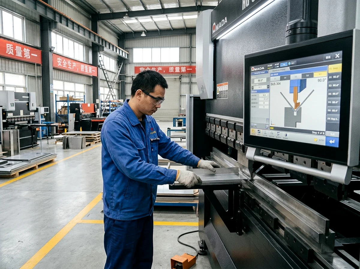
| 3. Precision CNC Bending | 170-Ton 7-Axis CNC Press Brake with Optical Laser Angle Sensor | Real-time springback compensation; standardized hardened precision ground tooling (R = 1.0T). | Bending angle repeatability held to ±0.3°; flange height within ±0.15 mm. |
| 4. Hardware Clinching | Haeger 824 OneTouch Automated Insertion Press | Calibrated hydraulic tonnage control with positive dwell time for cold metal flow. | Zero sheet bulging around studs; 100% torque retention verification. |
| 5. Seam Welding (If Needed) | Robotic Fiber Laser Welding / Pulse TIG Cell | Dedicated copper chill clamping fixtures to eliminate thermal distortion. | AWS D1.3 certified sheet metal weld integrity; full root penetration. |
| 6. Surface Finishing | Automated 5-Stage Chemical Pretreatment & Electrostatic Powder Line | Zirconium conversion coating followed by high-durability TGIC polyester powder (60–90 µm). | ASTM D3359 cross-hatch adhesion Grade 5B; 1,000-hour salt fog resistance. |

9. Thermal Interface Materials (TIM), Ceramic Washers & Vibration Isolators
Even with optimized sheet metal geometry, direct metal-to-metal bolted contact between the heater chassis and the container wall creates a conductive thermal short circuit. MSTFAB integrates certified non-conductive thermal accessories into our custom bracket kits:
1. Mica and Steatite Ceramic Insulating Washers
To break thermal bridging across mounting bolts, we supply high-purity phlogopite mica or steatite ceramic stepped insulating bushings. Rated for continuous exposure up to 600° C, these washers decouple fastener shank conduction, preventing bolt head heat from reaching the outer container wall.
2. High-Temperature Silicone & EPDM Vibration Dampers
For applications subjected to heavy low-frequency vibration (such as utility railcar BESS or mobile trailer microgrids), bracket mounting feet incorporate vulcanized silicone or high-durometer EPDM vibration isolators. These elastomeric grommets attenuate harmonic transmission while absorbing thermal expansion differentials between dissimilar metals.
10. Quality Metrology, CMM Inspection & AS9102 First Article Inspection (FAI)
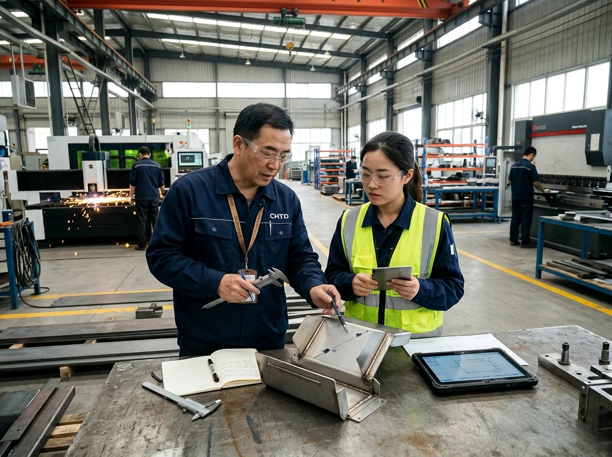
MSTFAB operates an ISO 9001:2015 certified quality management system backed by an advanced, climate-controlled metrology laboratory. Every new BESS heater bracket part number undergoes exhaustive First Article Inspection before mass production authorization:
Comprehensive FAI Deliverables Delivered with Pilot Batches
- AS9102 Form 1, 2, and 3 Reports: Comprehensive ballooned drawings linking 100% of CAD dimensions, geometric tolerances, and drawing notes to measured inspection data.
- Zeiss Bridge Coordinate Measuring Machine (CMM) Verification: Multi-point inspection verifying true position of critical mounting hole patterns to ±0.05 mm.
- Mill Test Reports (MTR) with Full Heat Traceability: Original mill test certificates documenting chemical composition (C, Cr, Ni, Mo) and mechanical yield/tensile properties for every raw sheet coil utilized.
- Coating Thickness & Adhesion Logs: Electromagnetic dry film thickness (DFT) measurements and destructive cross-hatch tape test records verifying zero paint flaking.
- PEM Fastener Destructive Torque & Push-Out Sampling: Calibrated mechanical pull tests guaranteeing fasteners exceed minimum manufacturer retention limits by ≥ 30%.
11. OEM Procurement Checklist: Specifications to Include with BESS RFQs
To secure a binding, production-ready manufacturing quote within 24 hours without engineering holds, submit the following technical documentation to MSTFAB:
- 3D CAD Assembly (.STEP / .STP): Native solid geometry showing the bracket, mating heater footprint, radiant shield, and container mounting interfaces.
- 2D Engineering Drawings (.PDF / .DWG): Fully dimensioned prints defining bilateral tolerances (ISO 2768-mK), designated Critical-to-Quality (CTQ) dimensions, and weld symbol callouts.
- Material Grade Callout: Explicit alloy and temper (e.g., 304 Stainless Steel #4 Brushed, 2.5 mm or Aluzinc DX51D+AZ150 2.0 mm).
- Hardware Schedule: Complete part numbers for self-clinching studs, standoffs, or weld nuts (e.g., PennEngineering FHS-M6-20).
- Coating & Surface Treatment Specification: Finish standard, RAL color code (e.g., RAL 7035 Light Grey), minimum DFT, and paint-masking zones for grounding studs.
- Target Volumes & Packaging Requirements: Pilot quantity (e.g., 20 pcs FAI) and annual scheduled release quantities (EAU); special export packaging requirements (ISPM-15 heat-treated wood crates, desiccated moisture-barrier foil bags).
13. Finite Element Analysis (FEA): Coupled Thermal-Structural Simulation
To validate bracket longevity under severe operational extremes, MSTFAB performs coupled multiphysics Finite Element Analysis (FEA) on complex BESS bracket weldments. By simulating steady-state thermal conduction alongside dynamic mechanical shock, our simulation engineers eliminate structural vulnerabilities prior to cutting production blanks:
1. Thermal Stress & Buckling Simulation
When an anti-condensation heater operates at full electrical load (up to 800W per unit), localized temperature gradients generate non-uniform thermal expansion. In unconstrained brackets, differential expansion creates compressive membrane stresses that induce oil-canning and elastic buckling across thin web faces. MSTFAB’s FEA modeling optimizes bracket flange thickness and adds strategic embossing ribs that channel thermal expansion harmlessly along longitudinal relief slots, holding Von Mises thermal stresses below 45% of material yield strength (σvm ≤ 0.45 σ_y).
2. Seismic Acceleration & Random Vibration Modeling
Subjecting the bracket-heater assembly to simulated 3-axis random vibration profiles (per MIL-STD-810H Method 514.8 and IEC 60068-2-64) ensures that weld seams and fastener clinches endure 25-year operational fatigue. Harmonic frequency sweeps identify localized resonances, allowing our engineers to adjust gusset angle geometry until first-mode natural frequencies shift well above the critical 35 Hz threshold.
14. Corrosion Protection in Coastal & Desert Solar+Storage Farms (ISO 12944 C5-M)
Utility-scale BESS installations are frequently co-located with offshore wind landing stations, coastal solar fields, and desert microgrids. Environmental corrosivity in these locations reaches ISO 12944 Category C4 (High) to C5-M (Very High Marine). To prevent structural bracket degradation, MSTFAB implements comprehensive multi-layer surface protection protocols:
| Atmospheric Environment | ISO 12944 Class | Recommended Alloy & Coating System | Salt Spray Endurance (ASTM B117) |
|---|---|---|---|
| Desert Solar / Arid In-Land | C2 – C3 (Low / Medium) | Aluzinc DX51D+AZ150 (Unpainted) or Powder Coated SPCC Cold Rolled Steel | 500 – 800 Hours |
| Industrial / Temperate Utility Grid | C3 – C4 (High) | 304 Stainless Steel (Electropolished or Passivated ASTM A967) | 1,000 – 1,500 Hours |
| Coastal Wind / Offshore Substation | C5-M (Very High Marine) | 316L Stainless Steel with High-Build Fluoropolymer / Ceramic-Silicone Coating | 2,500+ Hours (Zero Pitting) |
Partner with a Tier-1 BESS Sheet Metal Manufacturing Specialist
MSTFAB manufactures custom heater brackets, radiant heat shields, liquid cooling manifold supports, and certified electrical enclosures for utility-scale battery energy storage OEMs worldwide. Submit your CAD drawings today for a 24-hour DFM engineering review and firm quotation.
12. Comprehensive Engineering FAQs on BESS Heater Mounting Brackets
Why are PTC convection heaters preferred over traditional tubular elements in BESS cabinets?
Positive Temperature Coefficient (PTC) ceramic heaters possess a self-regulating thermal characteristic. As ambient temperature increases, electrical resistance spikes non-linearly, limiting the heater’s maximum surface temperature to safe thresholds (typically 180° C–220° C) even during fan failure. This inherent fail-safe behavior drastically reduces thermal runaway risks compared to traditional resistive tubular elements, which can heat past 500° C upon airflow loss.
What is the minimum recommended thermal standoff distance between a BESS heater bracket and the battery module casing?
Under UL 9540A and NFPA 855 design guidelines, active heaters should maintain a minimum physical separation of at least 100 mm from battery module casings when an unshielded line-of-sight exists. When equipped with an MSTFAB sheet metal radiant heat shield baffle (Figure 4), this clearance can be safely optimized down to 40 mm – 50 mm, conserving valuable footprint in high-density battery racks.
How does MSTFAB ensure electrical bonding continuity on powder-coated heater brackets?
We insert specialized copper-plated or stainless steel PEM grounding studs before coating and apply precision high-temperature polyimide or silicone masking dots over the stud base. Following oven cure, the masking is removed, exposing pristine bare conductive metal. Every production batch is 100% verified using digital micro-ohmmeters to confirm resistance remains below 0.05 Ω, complying with UL 508A Section 14 grounding criteria.
Can Aluzinc steel be used instead of 304 stainless steel to reduce project cost?
Yes. For indoor-rated BESS containers or desert solar installations where marine salt fog is absent, Aluzinc (55% Aluminum, 43.4% Zinc, 1.6% Silicon coated steel) offers an outstanding 35% to 45% raw material cost reduction compared to 304 stainless steel. Its unique alloy barrier provides galvanic self-healing on laser-cut edges, withstanding up to 800 hours of ASTM B117 salt spray testing.
What is MSTFAB’s typical production lead time for custom BESS bracket orders?
Rapid prototyping and First Article Inspection (FAI) pilot samples are typically completed within 5 to 7 working days following CAD signoff. Scaled production batches (500 to 10,000+ units) typically ship within 2 to 3 weeks, supported by blanket purchase order inventory buffer programs.
How do heater mounting brackets integrate with BESS liquid cooling systems?
In modern liquid-cooled BESS containers, heater brackets are strategically located in lower air intake plenums, isolated from liquid cooling quick-connect manifolds. MSTFAB often fabricates integrated multi-service mounting frames that simultaneously support heater elements, coolant manifold line brackets, and temperature sensor cables while maintaining distinct thermal zones.
 WeChat Contact
 WhatsApp Me Directly