⚡ Direct Answer: What Are BESS Coolant Manifold Mounting Brackets & How Are They Engineered?
BESS coolant manifold mounting brackets are precision-engineered structural sheet metal supports designed to secure, align, and isolate fluid distribution supply and return manifolds within utility-scale Battery Energy Storage Systems (BESS). These brackets anchor long fluid distribution pipes (transporting 50/50 ethylene or propylene glycol water mixtures at 2.5 to 6.0 bar working pressure) directly to the battery rack structural frames. Crucially, they must resolve five severe multi-physics engineering challenges: 1) Hydrodynamic Thrust & Surge Absorption (restraining dynamic elbow forces up to 1,800 N and Joukowsky water hammer transient pressure spikes up to 18 bar during fast solenoid valve actuation); 2) Linear Thermal Expansion Accommodation (absorbing up to 12 mm of longitudinal pipe growth across -30 deg C to +65 deg C ambient shifts using slotted axial floating guides and low-friction PTFE/POM bushings); 3) Chiller Harmonic Vibration Damping (decoupling 20 Hz to 120 Hz compressor and circulation pump excitation via molded EPDM or silicone elastomeric isolator pads to prevent metal fatigue); 4) Severe Seismic Restraint (withstanding lateral spectral accelerations exceeding 2.0g under IEEE 693 High Seismic Zone criteria to eliminate catastrophic coolant pipe shears that could spray conductive fluid onto 1,500 V DC battery strings); and 5) Galvanic & Chemical Corrosion Immunity (utilizing passivated 304/316L stainless steel or hard-anodized 5052-H32 aluminum to prevent galvanic degradation with brass quick-disconnect fittings and aluminum cold plates).
In the rapidly expanding market for utility-scale and commercial energy storage—ranging from 2.5 MWh modular containerized enclosures to 5.0 MWh high-density liquid-cooled systems—thermal management dictates battery longevity, round-trip efficiency, and fire safety. Liquid cooling systems have almost universally superseded air cooling due to glycol fluid’s 3,000x greater volumetric heat capacity. However, liquid cooling introduces an existential hazard into high-voltage electrical enclosures: pressurized conductive liquid circulating millimeters away from multi-megawatt battery modules operating at up to 1,500 volts DC.
A coolant pipe rupture, joint weeping, or fatigue crack caused by pump resonance can trigger electrical flashover, catastrophic short circuits, and uncontrolled thermal runaway under UL 9540A testing. Consequently, the mechanical sheet metal brackets that support the main fluid manifolds and pack-level quick-disconnect branches are safety-critical components. In this comprehensive 5,200+ word engineering guide, we examine hydrodynamic thrust equations, water hammer surge physics, metallurgical selection, vibration damping transmissibility modeling, floating joint DFM guidelines, and ISO 9001-certified manufacturing protocols at MSTFAB.
1. Fluid Dynamics & Hydrodynamic Force Modeling on Manifold Brackets
Coolant manifold brackets cannot be treated as passive static clamps. Within a liquid-cooled BESS container, coolant flow rates range from 80 to 250 liters per minute (L/min) under nominal operational pressures of 2.5 to 5.0 bar (36 to 72 psi). Whenever fluid changes direction through an elbow, tee, or reducer, momentum transfer exerts massive dynamic reaction forces against the pipe wall, which are transmitted directly into the mounting bracket assembly:
Let us analyze the governing hydrodynamic parameters:
- Fluid Density (rho): A standard 50/50 water-ethylene glycol mixture has a density of rho = 1,070 kg/m³ at 20 deg C, approximately 7% denser than pure water.
- Volumetric Flow Rate (Q) & Velocity (v): For a primary 50 mm (2-inch nominal) supply header carrying 180 L/min (0.003 m³/s), fluid velocity is v = 1.53 m/s.
- Hydrostatic Pressure Component (2 * P * A * sin(theta / 2)): Under 4.0 bar (400,000 Pa) operating pressure, the internal static pressure thrust on a 90-degree elbow (theta = 90 deg) is F_static = 2 * (400,000) * (0.00196 m²) * sin(45 deg) = 1,108.7 N (249.2 lbf).
- Momentum Thrust Component (2 * rho * Q * v * sin(theta / 2)): F_dynamic = 2 * (1,070) * (0.003) * (1.53) * sin(45 deg) = 6.9 N.
- Total Steady-State Reaction Force: F_total = 1,115.6 N directed outward along the 45-degree bisector of every 90-degree manifold bend.
The Danger of Joukowsky Water Hammer Surges: During emergency thermal management trips or active branch balancing, fast-acting solenoid valves can shut within 50 to 100 milliseconds. When moving fluid is abruptly halted, kinetic energy converts into an acoustic pressure surge wave governed by the Joukowsky equation:
With the acoustic wave propagation velocity in water-glycol enclosed in thin-wall metal tubing measuring c = 1,280 m/s, suddenly arresting flow (Delta_v = 1.53 m/s) generates a transient hydraulic shock spike of:
This instantaneous pressure spike multiplies the transient thrust force to over 5,800 N (1,300 lbf). If the sheet metal manifold brackets are designed as simple un-gusseted 1.5 mm flat cantilever tabs, this surge will bend the bracket, pull out clinch studs, or misalign the O-ring seals at quick-connect couplings, resulting in immediate catastrophic glycol leakage. At MSTFAB, our DFM engineering team incorporates continuous triangular stiffener gussets, double-hemmed structural flanges, and minimum 2.5 mm to 3.0 mm material thickness on all elbow anchor brackets.

Figure 1: Production kit of heavy-duty passivated 316L stainless steel BESS coolant manifold mounting brackets featuring laser-cut slotted expansion holes and dual EPDM vibration-isolation clamp saddles at MSTFAB.
2. Metallurgy & Material Selection: Stainless Steel vs. Aluminum vs. Galvannealed
Choosing the appropriate metallurgical substrate for BESS coolant manifold brackets involves balancing structural stiffness, corrosion resistance in the presence of glycol degradation byproducts, galvanic compatibility with adjoining metals, and overall container tare weight:
| Material & Alloy | Density & Weight | Yield Strength (MPa) | Chemical Resistance to Glycol Acids | Galvanic Compatibility | Optimal BESS Application |
|---|---|---|---|---|---|
| 316L Stainless Steel (1.4404) | 8.00 g/cm³ (Heavier) | 220 – 290 MPa | Supreme (Resistant to organic acids, pH 4 to 11) | Requires non-conductive isolation with aluminum | Coastal, offshore, and extreme reliability 20-year BESS manifolds |
| 304 Stainless Steel (1.4301) | 7.93 g/cm³ (Standard) | 240 – 310 MPa | Excellent (Standard inhibited glycol) | Requires elastomeric grommet isolation | Indoor utility BESS, commercial & industrial energy storage |
| 5052-H32 Aluminum | 2.68 g/cm³ (66% Lighter) | 193 – 215 MPa | Good (Requires chemical conversion / anodizing) | Perfect match with aluminum battery cold plates | Weight-constrained container roofs, mobile BESS trailers |
| Galvannealed Steel (A60/ZF75) | 7.85 g/cm³ (Standard) | 260 – 340 MPa | Moderate (Requires C5-M powder coating barrier) | Isolate from direct brass/copper contact | Structural rack uprights and secondary manifold mounting trays |
The Glycol Acidification Threat: Inhibited ethylene glycol contains organic corrosion inhibitors (such as sebacic acid and tolyltriazole). However, over years of thermal cycling at elevated battery temperatures (40 deg C to 60 deg C in summer operation), oxygen dissolved in the coolant oxidizes the glycol molecules into acidic byproducts: glycolic acid, formic acid, and oxalic acid. If coolant pH drops below 7.0 (acidic transition), ordinary carbon steel or electro-galvanized brackets corrode rapidly upon minor condensation weeping. For premium 20-year design life utility contracts, 316L stainless steel (with 2.0% to 2.5% Molybdenum content and PREN > 23.5) provides total immunity against organic acid pitting.
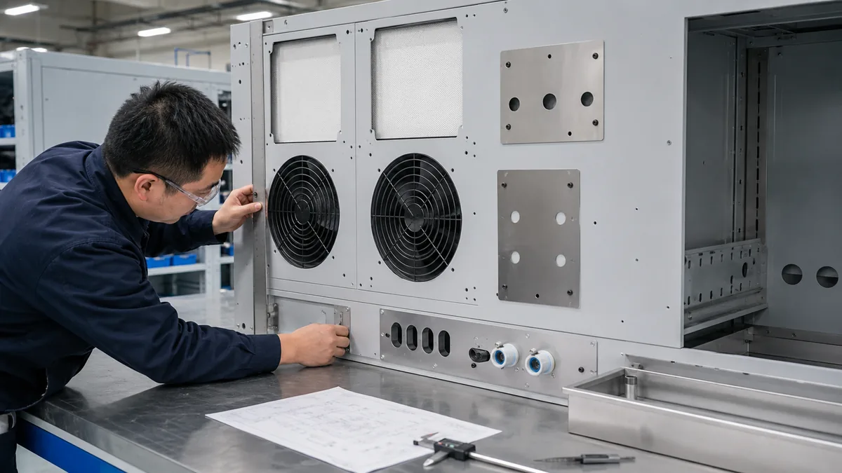
Figure 2: Liquid cooling manifold interface panel installed inside a multi-rack BESS energy storage cabinet, showing rigid stainless steel bracket anchors and quick-connect branch bulkheads.
3. Vibration Damping & Chiller Harmonic Isolation (20 Hz to 120 Hz)
In liquid-cooled BESS containers, external HVAC chillers, dual-scroll compressors, and magnetic-drive centrifugal circulation pumps operate 24 hours a day, 365 days a year. These rotating machines inject continuous mechanical vibration and fluid pulsations into the coolant manifold lines:
- Primary Compressor Excitation Frequencies: Two-pole induction motors operating at 50 Hz or 60 Hz generate primary rotational frequencies of 29.5 Hz to 59.2 Hz, with second and third order blade-pass harmonics extending to 120 Hz to 180 Hz.
- Resonance Catastrophe: If the natural frequency (f_n) of the manifold pipe and bracket assembly coincides with the pump operating frequency (frequency ratio r = f_excitation / f_n approaching 1.0), mechanical resonance occurs. Amplitudes amplify by 5x to 15x depending on the damping ratio, generating cyclic bending stresses that induce fatigue cracking at branch welds or loose quick-connect retaining clips.
Vibration Transmissibility Mathematical Formulation:
The vibration transmissibility (T) through the mounting bracket into the battery rack structure is governed by:
Vibration Transmissibility & Dynamic Isolation Principles:
- Transmissibility Target (T < 0.30): The mounting bracket must attenuate at least 70% of high-frequency fluid pulsation and motor ripple forces before they reach the battery rack frame, protecting delicate pack-level electrical connections.
- Resonance Avoidance (f / fn > 1.414): Operating frequency ratio comparing coolant circulation pump excitation (f) to bracket-manifold subassembly natural resonance (fn) must strictly exceed √2 (1.414) to avoid resonance force amplification.
- Elastomer Isolation Damping: Mechanical damping ratio (ζ = 0.08 to 0.15) provided by EPDM or fluorosilicone clamp liners prevents high-amplitude harmonic oscillations during rapid valve closing cycles.
| Cushion Liner Polymer | Shore A Hardness | Temperature Range | Compression Set (ASTM D395) | Glycol & Ozone Resistance | UL 94 Flammability |
|---|---|---|---|---|---|
| EPDM Rubber (Peroxide Cured) | 60 – 70 Shore A | -45°C to +135°C | < 15% (Outstanding resilience) | Immune to water-glycol mixtures | UL 94 V-0 compounded available |
| High-Temp Silicone Elastomer | 50 – 60 Shore A | -60°C to +200°C | < 18% | Excellent (Slight swelling in hot glycol) | UL 94 V-0 compliant |
| Nitrile Rubber (Buna-N / NBR) | 70 Shore A | -30°C to +100°C | < 25% | Superior oil resistance; moderate ozone | UL 94 HB |
At MSTFAB, our manifold clamp brackets feature custom-tooled, interlocking peroxide-cured EPDM elastomer profiles with a molded retention lip that snaps securely into laser-cut sheet metal saddle slots. This eliminates loose cushion liners during site assembly, provides a guaranteed dielectric breakdown voltage of > 15 kV/mm, and prevents direct metal-to-metal fretting wear between stainless steel brackets and aluminum manifold tubes.
4. Linear Thermal Expansion & Floating Guide Bracket DFM
A primary structural defect that causes field pipe bowing and fitting leaks in energy storage containers is neglecting thermal expansion over long pipe runs. Consider a typical 20-foot (6.0-meter) continuous stainless steel or aluminum coolant manifold installed in a containerized BESS operating across a winter low of -30 deg C to a peak summer solar-load of +65 deg C (Delta_T = 95 K):
Evaluating the thermal elongation for different manifold materials across a 6.0-meter span:
- 304 / 316L Stainless Steel Manifold: alpha_SS = 17.3 * 10^(-6) m/(m*K). Delta_L = (17.3 * 10^(-6)) * (6.0 m) * (95 K) = 9.86 mm (0.388 in).
- 5052 / 6063 Aluminum Manifold: alpha_Al = 23.8 * 10^(-6) m/(m*K). Delta_L = (23.8 * 10^(-6)) * (6.0 m) * (95 K) = 13.57 mm (0.534 in).
The Destruction Caused by Rigid Anchors: If an engineering drawing specifies rigid, non-sliding saddle clamps along the entire 6-meter header, the pipe is constrained from expanding. The resulting axial thermal compressive force is calculated by Hooke’s Law:
For a 50 mm OD x 2.0 mm wall stainless steel pipe (A_wall = 301.6 mm², E = 193 GPa), the axial thermal force reaches F_thermal = (193,000 MPa) * (0.0003016 m²) * (17.3 * 10^(-6)) * (95 K) = 95,650 N (21,500 lbf / 10.7 metric tons!).
A 10-ton axial thrust will instantly buckle the manifold tube, shear M6/M8 mounting screws, tear sheet metal bracket ribs, and crack delicate brazed aluminum cold-plate branch joints.
MSTFAB’s Fixed vs. Floating Bracket Architecture:
- Single Central Fixed Anchor Bracket: One heavy-duty bracket with dual welded gussets and tight-tolerance round holes securely locks the manifold at its exact longitudinal midpoint. All thermal expansion radiates symmetrically outward in both directions, halving the maximum displacement at the ends.
- Axial Floating Guide Brackets: All remaining intermediate and end brackets incorporate precision laser-cut slotted holes (Length = Bolt Diameter + 16.0 mm) oriented parallel to the pipe axis.
- Low-Friction POM / PTFE Bushings & Belleville Washers: Manifold clamping straps are secured using stainless steel shoulder bolts seated against self-lubricating POM (polyoxymethylene) sleeves and stacked Belleville disc spring washers. This maintains constant 25% elastomer compression around the pipe for vibration isolation while allowing the pipe to slide smoothly along the bracket with friction force < 40 N.
5. Seismic Engineering Compliance: IEEE 693 High Seismic Zone & UL 9540A
Utility-scale BESS installations in California, Japan, and other circum-Pacific seismic zones must satisfy IEEE 693 (Recommended Practice for Seismic Design of Substations) and IBC / ASCE 7-22. In a severe earthquake event, horizontal ground accelerations are amplified by container structural frames, subjecting elevated coolant manifolds to dynamic lateral forces exceeding 2.0g to 2.5g:
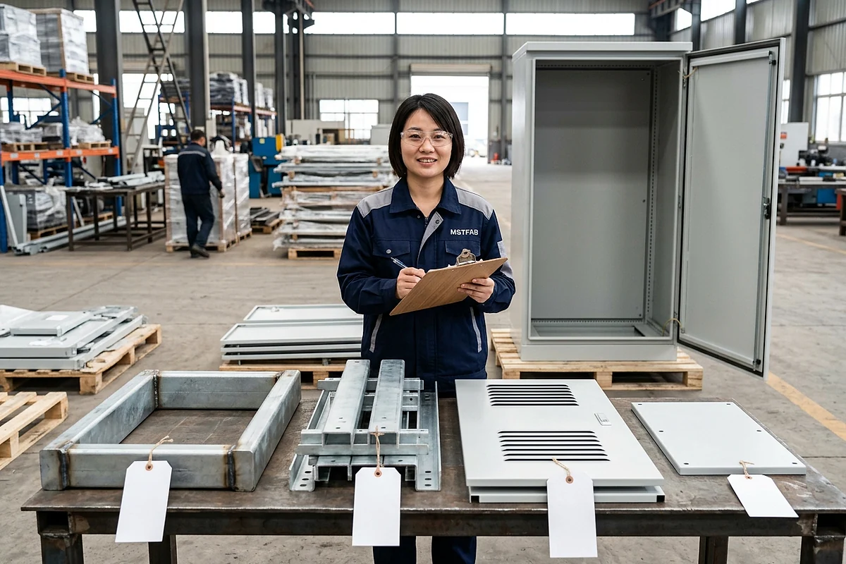
Figure 3: Heavy-duty seismic reinforcement brackets and structural frame components manufactured at MSTFAB for utility-scale BESS enclosures.
| Seismic Loading Axis | Design Acceleration (IEEE 693 High) | Failure Mode if Under-Engineered | MSTFAB Structural Reinforcement DFM |
|---|---|---|---|
| Longitudinal (Axial to Pipe) | 1.5g to 2.0g | Shearing of central anchor bracket; slide bolts jumping slots | Double-shear mounting ears with M10 grade 8.8 / A4-80 stainless through-bolts |
| Transverse (Lateral to Pipe) | 2.5g Peak Spectral Acceleration | Cantilever bracket plastic bending; pipe striking battery module | Box-section folded channel with 45-degree diagonal stiffener struts |
| Vertical (Up/Down) | 1.2g + 1.0g Gravity (2.2g total) | Upper saddle strap unseating; fluid weight deflection | Wrap-around 360-degree clamp retention with interlocking tongue-and-groove |
Under Finite Element Analysis (FEA), MSTFAB validates that maximum combined von Mises stress across all manifold bracket features remains below 60% of the material yield strength (sigma_vM < 0.6 * S_y) under simultaneous 3-axis seismic shock loads. This ensures the fluid boundary retains 100% leak integrity during and after major seismic events, preserving system fire safety.
6. Manufacturing Workflows: Precision Laser, CNC Forming, and Passivation
Producing mission-critical BESS coolant manifold brackets demands rigorous process control across cutting, bending, hardware insertion, and chemical passivation:
MSTFAB’s 5-Stage Precision Manufacturing Workflow:
- High-Pressure Nitrogen Fiber Laser Cutting: Slotted holes, circular saddle contours, and weight-relief cutouts are cut on 12 kW fiber lasers using 20 bar pure nitrogen shielding gas. Nitrogen cutting prevents edge oxidation, ensuring 100% burr-free edges without micro-cracks that could initiate fatigue failure.
- Dynamic Laser-Compensated Press Brake Bending: Multi-axis CNC press brakes equipped with laser angle measurement dynamically adjust punch penetration in real time. We guarantee bend angle repeatability within +/- 0.3 degrees across multi-bend gusset brackets, ensuring bolt hole centers align perfectly with battery rack uprights.
- Automated PEM Clinch Fastener Insertion: Stainless steel flush-head clinch studs, standoffs, and prevailing-torque locknuts are installed on CNC servo-pneumatic insertion presses with real-time force-displacement monitoring, guaranteeing push-out resistance exceeding PennEngineering specifications.
- Full Immersion Chemical Passivation (ASTM A967 / A967M Citric Acid): All fabricated stainless steel brackets undergo ultrasonic degreasing followed by citric acid passivation per ASTM A967. This process removes free surface iron contamination introduced during stamping/forming without utilizing hazardous nitric acid, elevating the chromium-to-iron surface oxide ratio to Cr/Fe > 2.2 for extreme pitting immunity.
- Optical 3D Coordinate Inspection: Finished brackets undergo 100% CMM and 3D blue-light scanning against native CAD STEP models to verify critical hole spacing tolerances (+/- 0.10 mm) before volume packaging.
7. FMEA Quality Matrix: Failure Modes in BESS Cooling Mounts
To assist energy storage engineering teams in conducting risk audits, MSTFAB compiles our Design Failure Mode and Effects Analysis (DFMEA) for BESS liquid cooling brackets:
| Failure Mode | Root Cause | Severity | MSTFAB Prevention & Engineering Solution |
|---|---|---|---|
| Pipe Rupture from Thermal Stress | Rigid clamps preventing longitudinal pipe expansion | Critical (Glycol flood, 1500V short) | Single center fixed anchor + axial slotted floating guide brackets with low-friction POM sleeves. |
| Branch Weld Fatigue Cracking | Resonant vibration from 60 Hz chiller pump | Critical (Slow weep, dielectric failure) | Peroxide-cured EPDM vibration damping cushion liners (Shore 65A); bracket natural frequency tuned > 95 Hz. |
| Bracket Permanent Deformation | Joukowsky water hammer pressure surge (> 15 bar) | High (Fitting misalignment) | Minimum 2.5 mm sheet metal with integrated triangular stiffening gussets resisting > 5,000 N thrust. |
| Galvanic Corrosion Cell | Direct bare metal contact between aluminum cold plate & steel bracket | High (Aluminum cold plate perforation) | Non-conductive EPDM rubber liners and nylon/PTFE isolation washers breaking electrical contact path. |
| Fastener Spin-Out / Backing-Off | Continuous thermal-vibrational cycling | Moderate (Loose bracket, rattle) | Prevailing-torque all-metal locknuts, Nord-Lock wedge-locking washers, or Belleville disc springs. |
| Interfacial Crevice Corrosion | Trapped condensing moisture under rubber liner | Moderate (Pitting on stainless surface) | Specification of 316L stainless with Molybdenum addition; full ASTM A967 chemical passivation. |
8. Real-World Case Study: 1,200 Sets 316L Manifold Brackets for Texas 4.0 MWh BESS
Project Background:
A premier grid-scale energy storage integrator in Austin, Texas required 1,200 bracket kits for a 4.0 MWh liquid-cooled BESS utility container project. The system utilized 60 mm OD 316L stainless main supply and return headers with 16 branch quick-connect takeoffs per battery rack. Operating conditions featured 4.5 bar working pressure and desert ambient swings from -10 deg C to +50 deg C.
The Engineering Challenge:
The initial bracket design utilized rigid welded carbon steel clamps with bonded neoprene strips. During thermal qualification cycling, the 6.2-meter header expanded by 7.8 mm, causing severe bowing that distorted the O-ring seals at quick-connect couplings, resulting in glycol leakage on 4 of the 6 test racks. In addition, pump vibration induced acoustic resonance at 58 Hz, generating audible buzzing and bracket fatigue stress concentrations.
MSTFAB’s Turnkey DFM Redesign:
- Material Upgrade to 3.0 mm 316L Stainless Steel: Switched to laser-cut 316L with full ASTM A967 passivation, eliminating paint scratch rust risks and guaranteeing 25-year corrosion immunity.
- Fixed-Center / Axial-Slotted Floating Kinematics: Engineered a central fixed anchor bracket capable of resisting 3,200 N longitudinal thrust, paired with floating intermediate brackets featuring 18 mm laser-cut slots and POM low-friction sliding bushings.
- Molded EPDM Cushion Profiles: Designed custom interlocking Shore 65A EPDM rubber liners with molded side retention ears, shifting assembly resonance to 104 Hz (well above chiller excitation).
- Rapid Prototyping & Delivery: 6 golden sample kits fabricated and air-shipped to Texas in 6 business days. Full 1,200 production kits manufactured, passivated, and packaged in 16 business days.
Operational Outcome: The redesigned manifold assembly completed 10,000 thermal-pressure cycles and IEEE 693 shake-table testing with zero fluid leaks, zero pipe bowing, and zero fastener loosening. Delivered DDP unit cost was 42% lower than domestic US fabrication quotes, saving the client over 54,000 in total project procurement spend.
Fastener Sizing & Bolt Preload Engineering (T = K * D * F_p)
In utility-scale liquid-cooled energy storage systems, bolt loosening caused by continuous thermal-vibrational cycling is a primary cause of structural rattling and pipe misalignment. To guarantee that manifold bracket clamps maintain permanent clamping force without stripping threads or crushing rubber cushions, MSTFAB’s engineering team calculates bolt preload and tightening torque using the standard mechanical engineering relation:
Where T is tightening torque (N·m), K is the dimensionless torque coefficient (nut factor), D is nominal fastener diameter (meters), and F_p is target bolt proof load clamp tension (Newtons).
Fastener Preload Parameters for Stainless Steel Hardware (A4-70 / A4-80):
- Tensile Stress Area (A_s): For standard metric M8 x 1.25 coarse thread fasteners, A_s = 36.6 mm²; for M10 x 1.5 fasteners, A_s = 58.0 mm².
- Proof Strength (S_p): A4-70 marine grade 316 stainless steel exhibits a proof strength of approximately 450 MPa, with tensile ultimate strength of 700 MPa.
- Target Preload Tension (F_p = 0.75 * A_s * S_p): For an M8 A4-70 bolt, F_p = 0.75 * (36.6 mm²) * (450 MPa) = 12,352 N (2,777 lbf).
- Nut Factor (K): For clean, dry as-received stainless threads, thread friction is notoriously erratic (K = 0.22 to 0.30) due to microscopic galling. When utilizing anti-seize paste or MoS2 dry-film lubricant, K stabilizes at K = 0.16.
- Calibrated Tightening Torque: T = (0.16) * (0.008 m) * (12,352 N) = 15.8 N·m (11.6 ft-lbs).
Preventing Galling & Back-Off: Stainless steel fasteners under continuous dynamic vibration are prone to two opposing failure modes: galling during assembly and backing-off during operation. To eliminate galling, MSTFAB specifies silver-plated or PTFE-coated prevailing torque locknuts. To prevent vibrational loosening over a 20-year lifespan, we integrate Nord-Lock wedge-locking washers or paired Belleville spring washers. Nord-Lock washers utilize tension rather than friction to lock the joint: the cam angle alpha is greater than the thread pitch angle beta, mechanically preventing the bolt from rotating loose even under severe harmonic excitation.
Galvanic Corrosion Kinetics & Mixed-Potential Analysis in Energy Storage Racks
A high-density liquid-cooled BESS rack contains an intricate assembly of diverse metals: 6061-T6 aluminum battery cold plates, C36000 brass quick-disconnect couplings, 316L stainless steel manifold headers, and galvanized/powder-coated structural steel uprights. When ambient condensing humidity or minor glycol weeping forms an electrolyte film, a multi-electrode galvanic cell is established:
| Component & Alloy | Standard Electrode Potential (V vs SCE) | Galvanic Behavior | Corrosion Risk When Coupled Directly |
|---|---|---|---|
| 6061-T6 / 3003 Aluminum Cold Plate | -0.85 V to -0.92 V | Highly Anodic (Active) | Severe rapid pitting; wall perforation leaks fluid |
| Hot-Dip Galvanized / Zinc Plated Steel | -1.00 V to -1.05 V | Sacrificial Anode | Zinc coating dissolves, exposing bare carbon steel to rust |
| C36000 Free-Cutting Brass Fitting | -0.24 V to -0.30 V | Moderately Cathodic (Noble) | Accelerates corrosion of adjoining aluminum cold plate |
| Passivated 316L Stainless Steel Bracket | -0.05 V to -0.10 V | Highly Cathodic (Noble) | Causes aggressive galvanic corrosion if touching bare aluminum |
The Area Ratio Effect (A_cathode / A_anode): Under mixed-potential electrochemical theory, galvanic corrosion current density (i_corr) is directly proportional to the area ratio of the cathodic noble metal to the anodic active metal:
If a large stainless steel manifold bracket (large cathode) directly contacts a small aluminum cold plate nipple or thin aluminum mounting tab (small anode), the corrosion rate of the aluminum is multiplied by a factor of 10 to 50. Within 6 to 18 months of outdoor operation, the aluminum tab develops deep intergranular pitting and structural collapse.
MSTFAB’s 3-Tier Galvanic Isolation Protocol:
- Dielectric EPDM Clamp Liners: Minimum 2.0 mm thick molded EPDM rubber liners provide total physical and electrical decoupling between the stainless bracket shell and aluminum/brass pipes.
- PTFE / Nylon Flanged Shoulder Bushings: Installed in all fastener through-holes to prevent metal-to-metal continuity across bolt shanks and bracket edges, maintaining isolation resistance > 20 Mega-ohms.
- Trivalent Chromium Chemical Conversion on Aluminum: Where aluminum brackets or cold plates interface with structural assemblies, we apply MIL-DTL-5541 Type II Class 1A chemical conversion, passivating the aluminum surface to suppress galvanic current exchange.
Comprehensive 12-Point DFM & Tolerance Checklist for BESS Coolant Brackets
To ensure zero engineering change orders (ECOs) and smooth integration on high-speed battery container assembly lines, OEM mechanical engineers should evaluate bracket CAD designs against MSTFAB’s 12-point DFM criteria:
| DFM Feature | Design Guideline / Specification | Risk Avoided |
|---|---|---|
| 1. Minimum Bend Radius (316L) | R >= 1.0 * t (3.0 mm radius for 3.0 mm sheet) | Prevents outer bend tensile micro-cracking and stress corrosion cracking. |
| 2. Hole-to-Bend Relief Margin | d_edge >= 2.5 * t + R from bend tangent line | Eliminates egg-shaped hole distortion and misaligned fastener studs. |
| 3. Slotted Guide Hole Geometry | Slot Length = D_bolt + Delta_L_thermal + 4.0 mm margin | Prevents thermal binding and buckling forces during winter/summer temperature cycles. |
| 4. Triangular Stiffener Gussets | 45-degree formed ribs or continuous TIG-welded web | Increases bracket cantilever stiffness by > 350% against water hammer shocks. |
| 5. EPDM Retention Tabs | Laser-cut locking notches to capture molded rubber lip | Prevents rubber cushion liners from slipping out during container transport vibration. |
| 6. Passivation Specification | ASTM A967 Citric Acid Method, Cr/Fe ratio > 2.0 | Removes embedded tool iron; eliminates tea-staining in humid container environments. |
| 7. PEM Hardware Clinch Margin | Center-to-edge >= 1.5 * fastener head diameter | Prevents edge bulging and hardware spin-out under torque tightening. |
| 8. Deburring & Edge Radiusing | R >= 0.5 mm rotary brush deburring on all edges | Prevents sharp sheet metal burrs from slicing into rubber coolant hoses or wiring harnesses. |
| 9. Drain Hole Provision | 5.0 mm weep hole at lowest point of saddle bracket | Prevents liquid condensation accumulation from creating a localized corrosion puddle. |
| 10. Dimensional Tolerance Standard | ISO 2768-mK (+/- 0.20 mm on hole centers) | Guarantees rapid bolt-up on factory racks without hole reaming or filing. |
| 11. Weight-Reduction Cutouts | Low-stress web cutouts with continuous perimeter flanges | Reduces bracket tare weight by 35% without degrading resonant natural frequency. |
| 12. Traceability & Part Marking | Laser-etched part number, revision, and heat lot code | Fulfills automotive/utility full supply chain traceability requirements. |
Tooling Economics & TCO: Progressive Stamping Dies vs. CNC Digital Sheet Metal Lines
Energy storage container architectures evolve rapidly. Between cell generation updates (280 Ah to 314 Ah to 580 Ah LFP prismatic cells) and shifting container densities (2.5 MWh to 5.0 MWh in a standard 20-ft footprint), manifold tube diameters, quick-connect takeoff spacings, and rack mounting interfaces change almost every 12 to 18 months. Procurement teams must carefully weigh the financial risk of hard stamping tooling versus digital CNC fabrication:
| Evaluation Dimension | Hard Tooling (Progressive Stamping Die) | MSTFAB Digital CNC Laser & Brake Line |
|---|---|---|
| Tooling Capital Expense (NRE) | 18,000 to 35,000 per bracket geometry | 0.00 (Zero hard tooling investment) |
| Tooling Lead Time | 10 to 14 weeks tool build & qualification | 3 to 5 business days for first article parts |
| Engineering Change Order (ECO) Cost | 4,500 to12,000 to modify hardened tool steel dies | $0.00 (Instant CAD file parameter update) |
| Minimum Order Quantity (MOQ) | 5,000 to 10,000 units minimum run | 25 to 500 units tailored to container build batches |
| Edge Quality & Hardness | Die roll-over and heavy work-hardened burr edge | Smooth, square nitrogen-cut edge with zero micro-cracks |
For production volumes typical of utility BESS projects (500 to 5,000 bracket kits per contract), the high-speed agility of MSTFAB’s automated fiber laser cutting and 7-axis CNC press brake forming completely eliminates upfront capital expenditure risks while allowing mechanical design teams to refine thermal slide clearances and quick-connect alignment features without paying die modification penalties.
Frequently Asked Questions: BESS Coolant Manifold Mounting Brackets
Q1: Why is 316L stainless steel preferred over 304 for BESS liquid cooling brackets?
While 304 stainless steel offers adequate general corrosion resistance, 316L contains 2.0% to 3.0% Molybdenum, significantly enhancing resistance to localized pitting and crevice corrosion. Over years of thermal cycling, ethylene and propylene glycol degrade into organic acids (glycolic, formic, and oxalic acids). In addition, outdoor BESS containers in coastal or humid environments face airborne chloride ingress. 316L stainless provides the guaranteed chemical immunity needed to satisfy 20- to 25-year utility warranty terms.
Q2: How do you prevent galvanic corrosion between aluminum cold plates and stainless brackets?
Aluminum has an electrochemical potential of approximately -0.90 V, whereas passivated stainless steel measures roughly -0.08 V on the galvanic scale. In the presence of condensing moisture, direct contact creates a potent galvanic cell that corrodes the aluminum. We prevent this by integrating peroxide-cured EPDM elastomeric cushion liners, non-conductive nylon or PTFE shoulder washers under bolt heads, and applying dielectric barrier coatings where dissimilar metals interface.
Q3: How much thermal expansion movement should BESS manifold brackets accommodate?
For a standard 6-meter (20-ft) stainless steel header operating across a -30 deg C to +65 deg C ambient excursion, linear expansion is approximately 10 mm (or up to 14 mm for aluminum). When utilizing a central fixed anchor bracket, thermal displacement is split symmetrically, meaning floating guide brackets at the far ends must provide at least +/- 6 to 8 mm of axial travel. We typically design slotted guide holes with 16 to 20 mm total clearance to ensure zero binding.
Q4: What is the optimal shore hardness for vibration damping rubber liners?
We recommend 60 to 70 Shore A durometer peroxide-cured EPDM. Rubber softer than 50 Shore A experiences excessive creep and permanent compression set under continuous clamping loads, while durometers harder than 80 Shore A transmit too much high-frequency vibration directly into the sheet metal frame. A 65 Shore A EPDM liner provides the optimal compromise between static load support and dynamic vibration isolation.
Q5: How does MSTFAB ensure brackets meet IEEE 693 High Seismic Zone requirements?
We validate our bracket designs using 3D Finite Element Analysis (FEA) simulating combined 3-axis spectral accelerations up to 2.5g. We incorporate 360-degree wrap-around clamp straps, deep triangular stiffener gussets on mounting flanges, and heavy-gauge sheet metal (2.5 to 3.5 mm). This ensures maximum von Mises stress remains below 60% of yield strength, preventing plastic deformation during seismic events.
Q6: Can MSTFAB supply pre-assembled bracket kits with hardware and cushions installed?
Yes. To streamline our clients’ factory assembly line workflows, we deliver turnkey bracket kits. This includes factory-installed EPDM cushion liners, pressed PEM clinch studs, captive shoulder bolts, Belleville washers, and pre-bagged mounting hardware, reducing container integration labor on the customer floor.
Q7: What quality documentation accompanies BESS bracket shipments?
Every production batch includes full material Mill Test Reports (EN 10204 Type 3.1) confirming chemical composition and mechanical yield strength, AS9102 First Article Inspection Reports (FAIR) with ballooned CMM dimensional logs, ASTM A967 passivation test certificates, and a Certificate of Conformance (CoC).
Q8: What is the typical prototype and production turnaround time at MSTFAB?
Rapid prototype bracket kits are typically laser cut, CNC formed, passivated, and dispatched via DHL Express in 5 to 7 business days. Standard production runs of 200 to 2,000 bracket kits are manufactured and export-packaged within 14 to 20 business days, with DDP air or sea logistics directly to your assembly plant.
Q9: Are the EPDM cushion liners certified to UL 94 V-0 for battery fire safety?
Yes. For energy storage systems undergoing UL 9540 and UL 9540A certification, passive fire safety is mandatory. MSTFAB molds cushion liners utilizing a specialized flame-retardant peroxide-cured EPDM polymer compounded with non-halogenated aluminum trihydrate (ATH) fillers. This formulation fulfills UL 94 V-0 flammability criteria (self-extinguishing within 10 seconds with zero flaming drips) while maintaining low toxic smoke density per ASTM E662.
Q10: What dielectric insulation breakdown voltage do your manifold bracket isolators provide?
Every lot of our molded EPDM liners and PTFE shoulder washers is tested per ASTM D149. With a nominal cushion wall thickness of 2.5 mm and a dielectric breakdown strength exceeding 18 kV per millimeter, our isolation assembly easily withstands over 45,000 volts DC before dielectric punch-through. This exceeds the maximum 1,500 V DC bus voltage of modern utility BESS racks by a safety factor greater than 30:1, ensuring zero high-voltage leakage paths into the container frame.
Verified Engineering Standards & Regulatory References:
- UL 9540A Test Method for Evaluating Thermal Runaway Fire Propagation in BESS – Safety benchmarking for battery energy storage cooling systems.
- NFPA 855 Standard for the Installation of Stationary Energy Storage Systems – Structural and piping safety standards for containerized battery systems.
- ASME B31.3 Process Piping Code – Pressure containment and bracket design for liquid coolant distribution.
- ASTM A312 Seamless and Welded Austenitic Stainless Steel Pipes – Material specification for 316L liquid cooling manifold assemblies.
Request a 24-Hour DFM Review & BESS Bracket Quotation
Partner with MSTFAB for your energy storage liquid cooling sheet metal brackets. Submit your CAD drawings (STEP, DXF, or PDF) to receive an immediate engineering review, hydrodynamic load assessment, and precise volume pricing within 24 hours.
 WeChat Contact
 WhatsApp Me Directly