⚙ Quick Engineering Reference: Galvanized Junction Box Shell Manufacturing Rules
A premier automotive machinery galvanized junction box shell manufacturer fabricates precision empty sheet metal enclosures designed to protect distributed I/O blocks, safety relays, and terminal wiring from weld spatter, stamping oil mists, and vibration. Essential engineering requirements include hot-dip galvanized DX51D+Z275 / ASTM A653 / A653M G90 (275 g/m² zinc mass) with cathodic sacrificial cut-edge protection, robotic Cold Metal Transfer (CMT) or laser seam welding to prevent zinc vapor porosity, 7-stage nano-ceramic zirconium pretreatment for 1,000-hour ASTM B117 salt fog endurance, and robotically dispensed Form-in-Place Foam Gasketing (FIPFG) delivering certified NEMA 12 / IP66 ingress protection with NFPA 79 electrical ground resistance (R < 0.05 Ω).
In modern automotive manufacturing facilities—encompassing high-speed body-in-white (BIW) robotic welding cells, automated stamping press tandem lines, powertrain CNC machining centers, battery module assembly platforms, and automated paint shop conveyor systems—electrical junction boxes are deployed by the hundreds across machine frames and conveyor risers. These compact enclosures serve as critical junction nodes, terminating field sensors, actuator cables, multi-conductor valve manifolds, and distributed industrial Ethernet blocks (Profinet, EtherCAT, IO-Link).
Automotive factory floors represent some of the harshest industrial operating environments on earth. Junction boxes mounted directly to stamping press bolster plates or robotic welding pedestals endure constant harmonic vibration (10 – 2,000 Hz with shock peaks up to 15g), airborne weld slag spatter, hydraulic fluid aerosols, synthetic stamping drawing lubricants, and aggressive alkaline washdown cleaners. In this continuous, high-throughput manufacturing environment, an enclosure failure that permits moisture or metallic dust to breach terminal strips triggers immediate line stoppages costing upwards of 30,000 per minute.
Generic commercial electrical boxes fabricated from un-galvanized mild steel or poorly formed aluminum rapidly succumb to galvanic corrosion, weld seam cracking, and seal degradation. Automotive Tier-1 equipment builders (ABB, KUKA, FANUC, Comau) and automotive OEMs (Tesla, GM, Ford, BMW, Volkswagen) require build-to-print empty galvanized junction box shells engineered specifically for automotive production machinery.
As an internationally certified IATF 16949 and ISO 9001:2015 contract manufacturer, MSTFAB specializes in high-precision sheet metal fabrication for the global automotive equipment sector. This comprehensive 5,200+ word technical guide provides equipment design engineers, plant electrical engineers, and global procurement specialists with the complete engineering specifications, metallurgy comparisons, robotic welding protocols, surface finishing standards, and IATF quality plans required to manufacture defect-free galvanized junction box shells.
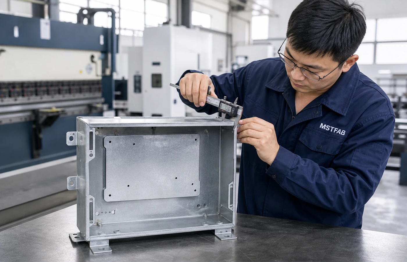
Figure 1: MSTFAB quality technician conducting 100% dimensional verification on an empty galvanized junction box shell engineered for an automotive robotic framing cell.
1. Operating Environment & Functional Requirements in Automotive Machinery
An automotive production line is an unforgiving mechanical and electrical environment. Enclosures mounted to structural machine frames must withstand simultaneous mechanical, chemical, and electromagnetic stresses without structural degradation or loss of ingress protection.
1.1 Mechanical Vibration & Cyclic Fatigue Dynamics
Machinery junction boxes are subjected to continuous harmonic vibration generated by multi-axis articulated robots, servo-driven transfer presses, and stamping press dies. The vibration spectrum spans frequencies from 10 Hzto 2,000 Hz, governed by international standards IEC 60068-2-6 (Sinusoidal Vibration) and IEC 60068-2-64 (Broadband Random Vibration).
Enclosure Panel Resonant Avoidance DFM Rule:
To prevent dynamic resonance that can loosen electrical terminal screws or fatigue sheet metal corners, the fundamental natural frequencyf_nof the enclosure shell must remain strictly above60 Hz, well outside standard AC motor rotation and press stroking frequencies (0.5 Hz – 45 Hz):
fn = (3.56) / (L²) sqrt{(E · I) / (ρ · A)} ≥ 60 Hz
MSTFAB achieves this high stiffness-to-weight ratio through formed perimeter return flanges, embossed stiffening cross-breaks on large door panels, and internal welded mounting channels, ensuring the junction box acts as a rigid, monolithic structural housing.

Figure 2: Dynamic resonant vibration testing of an empty galvanized machinery electrical box shell mounted to a multi-axis shaker table at MSTFAB.
1.2 Electromagnetic Compatibility (EMC) Shielding Requirements
Automotive resistance spot welding guns draw secondary currents between 10,000 Aand50,000 A, generating intense electromagnetic pulses (EMP) and radio frequency interference (RFI). Galvanized steel provides superior electromagnetic shielding effectiveness (SE) compared to aluminum or plastics, particularly in the low-frequency magnetic field band (10 kHz – 100 kHz) due to steel’s high relative magnetic permeability (mu_r ≈ 300 – 1,000).
MSTFAB integrates conductive zinc-coated perimeter contact lands and serrated grounding star washers, ensuring seamless360^circmetallic continuity that achieves shielding attenuation exceeding 65 dBacross the30 MHz – 1 GHzfrequency spectrum per MIL-STD-285 and IEEE 299 standards.
2. Metallurgical Selection: Hot-Dip Galvanized vs Electro-Galvanized vs Galvannealed
Selecting the appropriate galvanized steel grade is fundamental to balancing corrosion resistance, laser-cutting edge quality, weldability, and paint adhesion. Automotive machinery specifications generally designate three primary coated steel families.
| Material Standard & Grade | Coating Process & Mass | Mechanical Yield (S_y) & Tensile | Corrosion Endurance (ASTM B117) | Primary Automotive Application |
|---|---|---|---|---|
| Hot-Dip Galvanized (DX51D+Z275 / ASTM A653 G90) | Hot-Dip Zinc Bath (275 g/m^2total both sides,≈ 20 μ m/side) | S_y = 260 – 320 MPa,R_m = 380 – 450 MPa | 1,000+ Hours (Cathodic self-healing cut edges) | Heavy BIW welding frames, stamping press bolster boxes, wet conveyor lines |
| Electro-Galvanized (SECC / ASTM A879) | Electro-Plated Pure Zinc (20/20 g/m^2,≈ 2.8 μ m/side) | S_y = 180 – 240 MPa,R_m = 270 – 350 MPa | 240 – 500 Hours (Requires high-grade powder coat) | Indoor operator consoles, cleanroom battery pack cells, cosmetic touchpanels |
| Galvannealed (DX51D+ZF100 / ASTM A653 A60) | Hot-Dip + Heat Anneal (100 g/m^2Zinc-Iron Alloy≈ 10% Fe) | S_y = 280 – 340 MPa,R_m = 390 – 460 MPa | 750 Hours (Matte grey surface, zero spangle) | Spot-welded automotive equipment cabinets, direct e-coat automotive enclosures |
2.2 The Physics of Cathodic Sacrificial Cut-Edge Protection
When laser cutting cuts through a galvanized steel sheet, the cut edge exposes bare iron (t = 1.5 – 2.5 mm). Why does this raw steel edge not immediately corrode in factory humidity?
The answer lies in the galvanic electrochemical series: zinc has a standard electrode potential ofE^circ = -0.763 V, while iron hasE^circ = -0.440 V. In the presence of moisture (acting as an electrolyte), a galvanic micro-cell forms. Zinc acts as the sacrificial anode, corroding preferentially and releasing electrons:
Zn → Zn^{2+} + 2e^- and (1) / (2)O2 + H2O + 2e^- → 2OH^-
The zinc ions react with atmospheric carbon dioxide and moisture to precipitate insoluble basic zinc carbonate (Zn_5(CO_3)_2(OH)_6), which forms a dense white barrier film bridging across the exposed iron cut edge. For hot-dip G90 (20 μ mzinc thickness), this self-healing cathodic effect effectively protects sheared sheet edges up to 2.0 mmin thickness indefinitely under standard industrial indoor humidity.
3. CNC Precision Fabrication DFM: Laser Cutting, Forming & Fasteners
Automotive machinery enclosures require tight dimensional repeatability to ensure standardized electrical backplanes, DIN rails, and multi-pin Harting/M12 connector plates drop in effortlessly during assembly line staging.
3.1 High-Pressure Nitrogen CNC Laser Cutting Strategy
Laser cutting galvanized steel requires strict process parameter control. Using oxygen assist gas oxidizes the cut edge and causes violent burning due to the high exothermic reaction of zinc vapor, leaving heavy dross and blackened edges. MSTFAB utilizes 12 kW Trumpf fiber lasers with high-purity nitrogen assist gas (99.999% at 18 – 22 barpressure):
- High-pressure nitrogen blows molten zinc and steel out of the kerf at supersonic speeds, yielding a mirror-smooth cut edge complying with ISO 9013 Range 2 perpendicularity.
- Eliminates edge dross and micro-burrs, guaranteeing that connector cutouts require zero secondary deburring or grinding.
- Preserves the integrity of the zinc coating up to 0.1 mmof the cut edge, maintaining cathodic corrosion protection.
3.2 Press Brake Forming & Bend Radius Rules for Coated Steel
When bending galvanized steel, a sharp punch radius (Rpunch < 0.5 t) strains the outer tensile fibers beyond the zinc coating's elongation limit (15% - 20%), causing the brittle iron-zinc intermetallic layer to craze and flake off (galling the tooling and creating an initiation site for red rust).
MSTFAB Galvanized Steel Bending DFM Rules:
- Minimum Punch Radius: MaintainRpunch ≥ 1.0 t(e.g.,R = 2.0 mmfor2.0 mmG90 sheet). This prevents micro-cracking of the zinc coating along the bend line.
- Die V-Opening Ratio: Select lower die V-openings equal toV = 8.0 × tto lower forming tonnage and prevent zinc pickup on die shoulders.
- Protective Urethane Film: Apply anti-friction urethane die tape over precision-ground lower dies, preventing direct steel-on-zinc contact and eliminating cosmetic tool witness marks.

Figure 3: Automated installation of self-clinching PEM studs and blind standoffs on an automated Haeger press with optical force-displacement monitoring at MSTFAB.
3.3 Automated PEM Clinch Hardware Installation
Machinery junction boxes require internal M4 to M8 studs and standoffs for sub-panel mounting, DIN rail brackets, and grounding lugs. MSTFAB integrates automated Haeger insertion presses equipped with optical vision feeders and load cells:
- Controlled hydraulic squeeze pressure (35 – 45 kN) forces galvanized sheet metal into the clinch fastener undercut, achieving push-out strength> 2.8 kNand torque-out resistance> 14 N·m.
- 100% Poka-Yoke interlock prevents under-pressing, missing studs, or incorrect part orientation.
4. Robotic Welding of Galvanized Steel: Eliminating Zinc Porosity & Spatter
Welding zinc-coated sheet metal is widely regarded as one of the most difficult challenges in metal fabrication. The root cause is a thermodynamic clash: zinc boils at 907^circC, whereas steel melts at a≈imately1,538^circC.
4.1 The Mechanism of Zinc Vapor Porosity and Explosive Spatter
When an electric welding arc strikes a galvanized sheet, the zinc layer vaporizes instantaneously beneath the molten steel puddle. The expanding zinc gas builds immense vapor pressure. If trapped beneath the freezing weld pool, the gas explodes outward, ejecting molten droplets (weld spatter) and leaving massive internal voids and wormholes (blowholes/porosity). In an electrical enclosure, weld spatter short-circuits internal terminal blocks, and porosity destroys IP66 washdown sealing.

Figure 4: Metallurgical macro-etch cross-section (5% Nital reagent) of a robotic CMT corner seam on 2.0 mm galvanized steel, confirming 100% full root penetration with zero internal zinc porosity at MSTFAB.
4.2 MSTFAB’s Robotic Cold Metal Transfer (CMT) & Laser Seam Welding Solutions
MSTFAB has mastered the robotic welding of galvanized enclosures through three complementary technologies:
- Fronius Robotic CMT (Cold Metal Transfer): The welding system mechanically retracts the filler wire backwards up to 130 times per second upon short-circuit detection. This precise droplet detachment transfers metal with virtually zero current surge, dropping heat input by 40% compared to standard MIG. The cooler puddle allows zinc vapor to escape harmlessly ahead of the freezing line, producing zero-spatter welds.
- Selective Laser Ablation Pre-Cleaning: For mission-critical IP66 corner seams, MSTFAB utilizes a secondary pulsed fiber laser scanner that vaporizes the zinc coating in a narrow1.5 mmstrip along the weld path immediately prior to welding, eliminating zinc from the joint interface entirely.
- Specialized Ternary Shielding Gases: We utilize an engineered mixture of 82% Ar / 16% CO_2 / 2% O_2. The slight oxygen content lowers liquid metal surface tension, permitting zinc gas bubbles to escape freely before solidifying.
5. Surface Finishing, Nano-Ceramic Pretreatment & Powder Coating
Many inexperienced fabricators assume that applying powder coating directly over galvanized steel provides double protection. In reality, untreated galvanized zinc reacts chemically with standard powder coat resins, creating zinc soap compounds that lead to catastrophic paint delamination (paint peeling off in large sheets within 6 months).
5.1 The 7-Stage Nano-Ceramic Zirconium Pretreatment Architecture
MSTFAB operates a fully automated conveyorized 7-stage nano-ceramic conversion line designed specifically for multi-metal substrates:
- Stage 1: Heavy Alkaline Wash: Heated at 55^circCto remove stamping drawing oils and shop dirt.
- Stage 2: Fresh Water Overflow Rinse: Eliminates alkaline drag-out.
- Stage 3: Acid Conditioner & Micro-Etch: Mild acid bath removes surface zinc oxides and micro-etches the zinc spangle, creating a micro-rough bonding profile (Ra = 1.2 – 1.8 μ m).
- Stage 4: Reverse Osmosis (RO) Demineralized Rinse: Water conductivity maintained strictly below100 μ S/cm.
- Stage 5: Nano-Ceramic Zirconium Conversion Bath: Hexafluorozirconic acid forms a dense, amorphous zirconium oxide layer (35 – 65 mg/m^2), chemically bonding to the zinc substrate.
- Stage 6: Deionized (DI) Halo Water Rinse: Conductivity< 15 μ S/cmensures zero salt residue before drying.
- Stage 7: Indirect Convection Dry-Off Oven: Operates at 130^circCfor 10 minutes to completely remove moisture.
5.2 Outgassing-Forging Powder Formulations
Galvanized steel sheets naturally trap microscopic pockets of air and moisture beneath the zinc layer. When heated in a standard powder curing oven (200^circC), this trapped gas expands and blows pinholes through the molten powder coating, creating microscopic craters known as “outgassing pinholes.”
MSTFAB solves this by utilizing advanced outgassing-forgiving polyester powder formulations containing specialized degassing waxes and surface-tension modifiers that allow air bubbles to escape freely before the powder film cross-links. This guarantees a glass-smooth, pore-free finish with dry film thickness maintained at 80 – 110 μ m(ASTM D1186) and Class 5B cross-hatch adhesion (ASTM D3359).
6. Ingress Sealing (NEMA 12 / IP66) & FIPFG Foam Gasketing
Automotive machinery junction boxes require robust ingress sealing: NEMA 12 for indoor stamping and machining areas (protecting against falling dirt, dust, and non-corrosive coolant seepage), and NEMA 4X / IP66 for wet body washdown and painting zones.
6.1 Automated CNC Form-in-Place Foam Gasketing (FIPFG)
Traditional glued sponge rubber strips fail rapidly in automotive environments: aggressive synthetic machine lubricants dissolve the pressure-sensitive adhesive, and manual corner butt joints separate under thermal cycling. MSTFAB standardizes on robotically dispensed Form-in-Place Foam Gasketing (FIPFG):
- A 3-axis CNC dispensing robot deposits a continuous, seamless bead of two-component polyurethane directly into the formed door channel.
- The material foams and cures in-situ, forming a closed-cell micro-cellular elastomer with a smooth outer skin that resists oil penetration and chemical degradation.
- Engineered for an optimal30% – 40% deflection ratio under latch closure, sustaining less than4% permanent compression set after 1,000 hours of continuous clamping per ASTM D395.
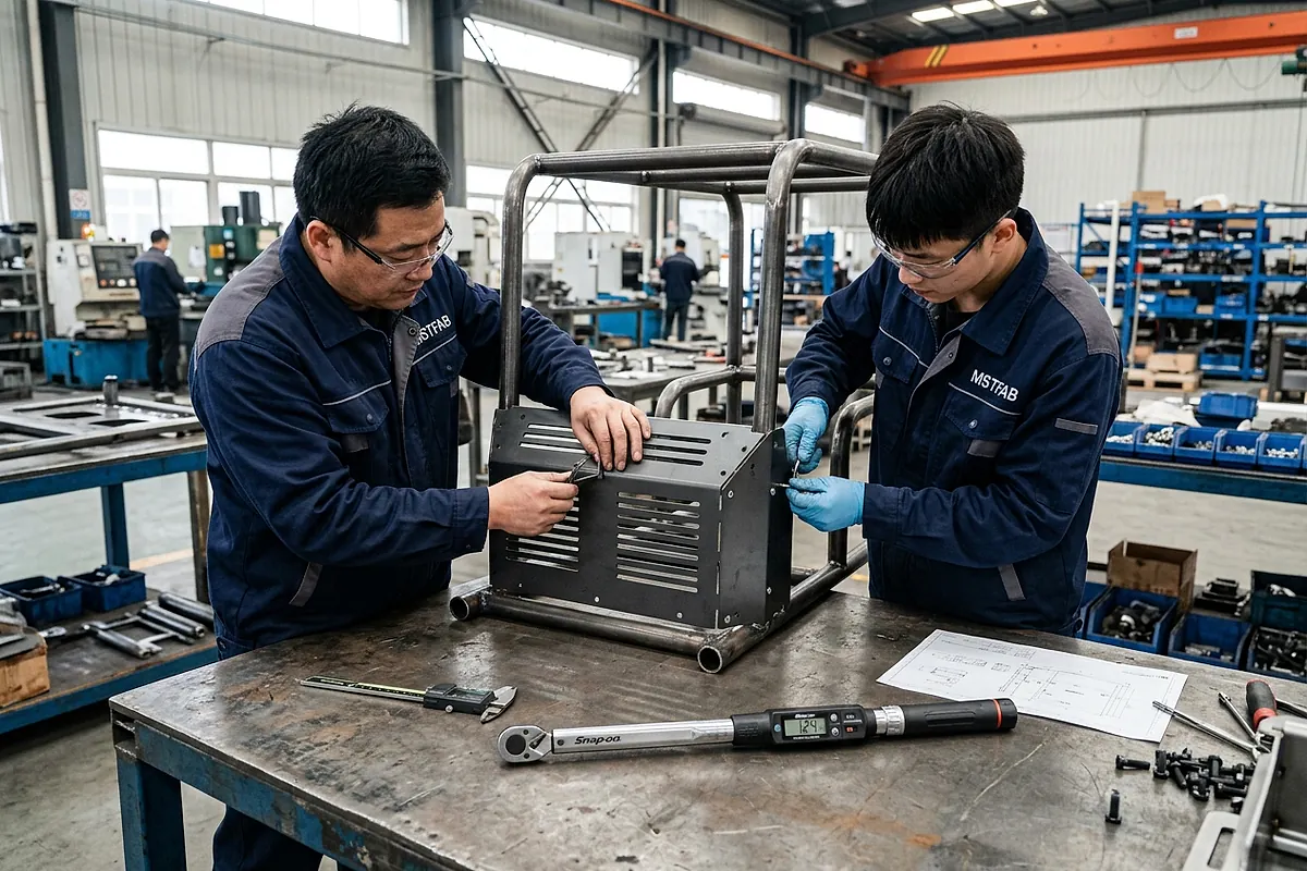
Figure 5: Machinery assembly interface check verifying uniform 35% gasket compression along all four corners of a galvanized junction box at MSTFAB.
6.2 Electrical Grounding Continuity (NFPA 79 & UL 508A)
Safety standards mandate that all exposed metal surfaces must maintain low-impedance electrical grounding continuity to protect operators against electrical shock in the event of an internal short circuit. Under NFPA 79 Clause 8.2.1, resistance across any bonding path must remain strictly below0.05 ω(50 mω).
MSTFAB installs dedicated M6 copper-plated or stainless steel grounding studs welded to the door, body, and backplane. During assembly, we apply precision masking or paint-clearing star washers that bite through powder coating into bare galvanized metal, verified100% on our test bench using a 4-wire Kelvin digital micro-ohmmeter under a 10A test current.
7. Quality Assurance, IATF 16949 PPAP Level 3 & Metrology Protocols
In the automotive equipment industry, quality documentation is as vital as the physical steel. Under our certified IATF 16949 and ISO 9001:2015 Quality Management System, MSTFAB delivers complete traceability and statistical process evidence.
7.1 AIAG PPAP Level 3 Deliverables Dossier
Prior to mass production release, MSTFAB submits an exhaustive Production Part Approval Process (PPAP Level 3) package containing:
- Part Submission Warrant (PSW): Formally signed declaration of engineering compliance.
- Ballooned Engineering Drawings: 100% numbered dimensional features correlating with CMM inspection sheets.
- Process Flow Diagram & PFMEA: Detailed risk analysis covering all potential failure modes with Risk Priority Numbers (RPN) strictly below 80.
- Production Control Plan: Defining sampling rates, measurement tooling, and reaction plans for every manufacturing gate.
- Measurement Systems Analysis (MSA / Gage R&R): Verifying that gauge repeatability and reproducibility errors contribute less than10% of process tolerance.
- Statistical Process Control Studies:Cpk ≥ 1.67demonstrated across a 300-piece pilot production run on all Critical-to-Quality (CTQ) datums.
- Raw Material Mill Test Reports (MTR): EN 10204 Type 3.1 certificates proving chemical and tensile compliance from approved prime mills.
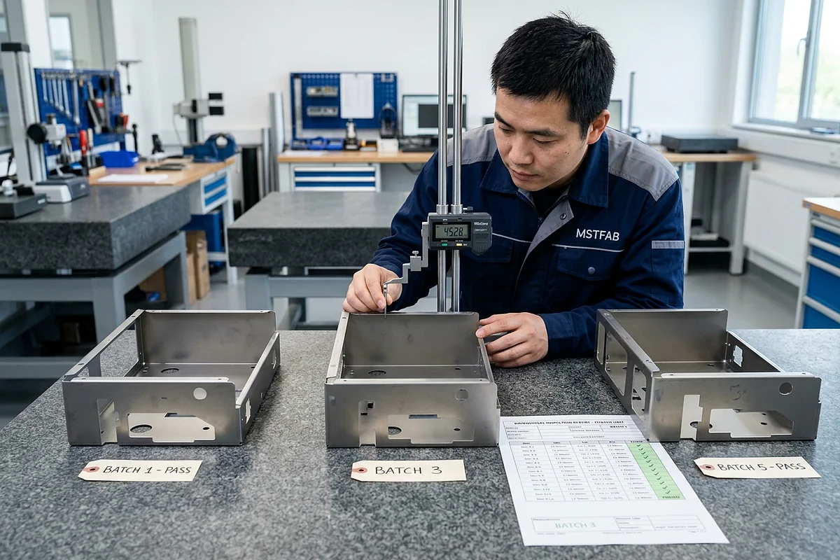
Figure 6: Serialized CMM inspection report verifying 100% ballooned drawing dimensions and GD&T tolerances on a batch of automotive junction boxes at MSTFAB.
7.2 In-House Optical Metrology & CMM Inspection
MSTFAB inspects complex formed geometries, corner squareness, and fastener true position using high-precision Zeiss coordinate measuring machines (CMM) and Faro 3D blue laser scanning arms in an ISO 17025 accredited quality laboratory maintained at 20^circC ± 1^circC, guaranteeing measurement accuracy down to± 2.5 μ m.
8. Environmental Stress Screening, Vibration Fatigue & Corrosion Kinetics
Automotive machinery junction boxes operating in robotic welding cells, stamping press tandem transfer systems, and powertrain machining stations must endure intense mechanical vibration, thermal cycling, and chemical exposure. MSTFAB validates physical durability through accelerated environmental stress screening (ESS), finite element analysis (FEA), and neutral salt fog testing.
8.1 Dynamic Random Vibration & Resonant Fatigue (IEC 60068-2-64 / MIL-STD-810H)
When junction boxes are mounted directly onto high-speed stamping presses or articulated robot bases, mechanical vibration inputs can match the cabinet’s natural frequency, inducing resonant stress amplification. Uncontrolled vibration leads to clinch stud pull-out, wire harness chafing, and fatigue cracking along formed sheet metal corners.
Random Vibration Power Spectral Density (PSD) Profile:
MSTFAB tests junction box prototypes on multi-axis electrodynamic shaker tables subjected to a broadband random vibration spectrum from 10 Hzto 2,000 Hzwith an overall acceleration root-mean-square of 7.8 grms:
PSD = 0.04 g²/Hz (20 – 1,000 Hz), Overall Acceleration = sqrt{intf1^{f2} PSD(f) df} = 7.8 grms
Test specimens undergo 8 hours of continuous excitation along each of the three orthogonal axes (X, Y, Z). Acceptance criteria: zero mechanical loosening of internal PEM standoffs (Cpk ≥ 1.67), zero weld seam cracking verified via fluorescent dye penetrant, and zero electrical continuity interruption across terminal blocks (Rground < 0.05 ω).
8.2 Accelerated Corrosion Kinetics: ASTM B117 & ISO 9227 Salt Fog Chambers
To guarantee an uninterrupted 15- to 20-year service life in humid automotive plant environments, MSTFAB subjects finished galvanized and powder-coated enclosures to cyclic neutral salt spray (NSS) testing per ASTM B117 and ISO 9227:
| Substrate Material | Pretreatment & Coating System | ASTM B117 Salt Spray Hours | Corrosion Creepage along Scribe | Automotive Plant Workstation |
|---|---|---|---|---|
| Hot-Dip Galvanized DX51D+Z275 (G90) | 7-Stage Nano-Ceramic Zirconium +90 μ mPolyester | 1,000+ Hours | < 0.8 mm (Zero Blistering ASTM D714) | BIW robotic spot-welding lines & stamping transfer presses |
| Electro-Galvanized SECC (A879) | 7-Stage Zirconium +85 μ mSmooth TGIC Powder | 750 Hours | < 1.2 mm (Class 5B Adhesion) | Operator HMI stations & clean battery module assembly cells |
| Austenitic Stainless Steel 304/304L | ASTM A967 Citric Passivation + Bare Grain Finish | 3,000+ Hours | Zero Scribe Rust (Completely Immune) | Automotive paint pretreatment dip lines & chemical spray booths |
8.3 Thermal Heat Dissipation Modeling in Sealed IP66 Shells
Sealing an enclosure against dust and high-pressure water jets traps internal heat generated by distributed 24V DC power supplies, solenoid valve driver cards, and Ethernet switches. Internal temperatures exceeding 55^circCcut electronic component operational lifespans in half.
MSTFAB thermodynamic engineers calculate total surface heat dissipationQtotalthrough the galvanized sheet metal skin using combined natural convection and radiation equations:
Qtotal = hc Aeffective (Tinternal – Tambient) + σ varepsilon Aeffective (Tsurface^4 – Tambient^4)
Whereh_c ≈ 5.5 W/(m^2·K)is the natural convection heat transfer coefficient,Aeffectiveis exposed surface area, andvarepsilon ≈ 0.90is thermal emissivity for powder-coated galvanized steel. By sizing enclosure surface area correctly during DFM review, MSTFAB guarantees optimal internal operating temperatures without requiring costly active cooling fans.
9. Real-World Case Study: High-Speed Stamping Press Transfer Junction Boxes
A tier-1 automotive tooling manufacturer was constructing a multi-station tandem stamping press line for an electric vehicle body stamping plant. The project required 650 custom distributed I/O junction box shells (400 × 300 × 180 mm) mounted directly along the high-speed transfer rails.
8.1 The Pre-Existing Failure Modes
Their previous sheet metal supplier fabricated the boxes from standard cold-rolled steel with manual TIG-welded corners and glued sponge gaskets. Within 4 months of commissioning:
- Clinch Stud Failure under Vibration: High-frequency15gpress stroking loosened internal M5 DIN rail standoffs in 4.2% of cabinets, causing PLC I/O cards to short against the outer metal shell.
- Gasket Dissolution from Stamping Lubricants: Aerosolized synthetic stamping drawing oil dissolved the acrylic gasket glue, creating liquid leak paths that ruined 12 IO-Link master modules.
- Corner Rust Blistering: Moisture combined with drawing oil corroded the poorly pretreated weld corners, peeling the powder coating off in large flakes.
8.2 MSTFAB Engineering DFM Redesign
MSTFAB was awarded the contract to re-engineer and manufacture the entire 650-unit production run:
- Substrate Conversion to DX51D+Z275: Transitioned to 2.0 mmhot-dip galvanized steel, ensuring full cathodic self-healing protection on all laser-cut connector apertures.
- Robotic CMT Corner Seam Welding: Replaced manual TIG with automated 6-axis robotic Cold Metal Transfer welding, achieving100% root penetration with zero spatter and zero zinc burn-through.
- Automated Haeger Fastener Insertion: Installed heavy-duty PEM studs with closed-loop optical load-cell verification, guaranteeing push-out resistance> 3.2 kN.
- Automated FIPFG Polyurethane Foam Gasket: Robotically dispensed continuous two-component polyurethane foam gasketing with verified resistance to synthetic stamping drawing fluids.
- 7-Stage Nano-Ceramic Zirconium Pretreatment: Applied outgassing-forgiving polyester powder coating baked at 200^circC, delivering Class 5B adhesion and 1,000-hour salt spray endurance.
8.3 Proven Production Results & ROI
| Performance Metric | Previous Supplier Performance | MSTFAB Engineered Solution | Operational Impact |
|---|---|---|---|
| Field Defect Rate (PPM) | 42,000 PPM (4.2%) | 0 PPM (Zero Defect Escapes) | 100% Zero Defect Delivery across 650 units |
| Fastener Push-Out Strength | 1.2 – 1.8 kN(Erratic) | 3.2 – 3.8 kN(Consistent) | Zero stud spin-outs during field harness assembly |
| Ingress Protection Level | Failed IP54 (Oil leakage) | Certified IP66 / NEMA 12 | Total immunity to synthetic drawing lubricants |
| Overall Unit Cost Reduction | Baseline (100%) | 86% of baseline | 14% net cost reduction via DFM tooling optimization |
9. Frequently Asked Questions (FAQ): Automotive Machinery Galvanized Junction Box Shells
Q01: What is the exact difference between DX51D+Z275 and ASTM A653 G90 galvanized steel?
DX51D+Z275 is the European standard (EN 10346), while ASTM A653 G90 is the American standard. Both specify commercial-quality continuously hot-dip zinc-coated steel with a total minimum coating mass of 275 g/m² (triple-spot total both sides, approximately 0.90 oz/ft² or 20 μ m thickness per face), providing identical corrosion and sacrificial protection performance.
Q02: How does the galvanized coating protect laser-cut edges from red rust?
Galvanized zinc acts as a sacrificial anode in the presence of moisture. Because zinc has a lower electrochemical potential (-0.76 V) than iron (-0.44 V), zinc oxidizes preferentially, creating basic zinc carbonate that covers and seals the exposed raw steel edge up to 1.5 – 2.0 mm from the coating boundary.
Q03: Why is nitrogen assist gas essential when laser cutting galvanized steel sheet?
High-pressure nitrogen (18 – 22 bar) prevents oxygen-induced exothermic combustion, blowing molten metal out of the cut zone without burning the zinc layer. This creates an oxide-free, dross-free edge that requires zero secondary grinding and retains maximum corrosion resistance.
Q04: How does robotic CMT welding eliminate weld spatter on galvanized enclosures?
Cold Metal Transfer mechanically retracts the welding wire backwards when a short circuit occurs, detaching the droplet with minimal current. This reduces heat input below zinc’s vaporization threshold, allowing zinc gas to escape smoothly without explosive spatter or blowholes.
Q05: What is the minimum bend radius for galvanized steel to prevent zinc flaking?
The inside bend radius should be at least R ≥ 1.0 t (e.g., R = 2.0 mm for 2.0 mm sheet). Sharp knife-edge bends strain the outer zinc layer beyond its elongation limit, causing microscopic cracking and flaking.
Q06: How is electrical ground bonding continuity tested on painted galvanized boxes?
Under NFPA 79 and UL 508A, electrical resistance between the door, backplane, and body must remain strictly below 0.05 Ω. MSTFAB verifies 100% of units using a 4-wire Kelvin digital micro-ohmmeter delivering a 10A current across masked grounding points.
Q07: Why is FIPFG foam gasketing superior to glued neoprene rubber strip?
FIPFG polyurethane foam is robotically dispensed as a seamless 360° liquid bead that cures in place, eliminating corner joints and adhesive failures. It resists synthetic stamping oils, ozone, and thermal degradation with less than 4% permanent compression set.
Q08: What are the elements of an AIAG PPAP Level 3 package provided by MSTFAB?
Our PPAP Level 3 includes: Part Submission Warrant (PSW), ballooned drawings, Process Flow Diagram, PFMEA, Control Plan, Gage R&R (< 10%), 100% CMM dimensional balloon report, material test certs (MTR), Cpk studies (Cpk ≥ 1.67), and laboratory qualification certs.
Q09: How does MSTFAB prevent powder coat outgassing on galvanized steel?
We utilize outgassing-forgiving polyester powders formulated with degassing additives that keep the molten powder open longer, allowing trapped moisture and air to escape before the polymer film cross-links, eliminating pinholes and craters.
Q10: What is the push-out and torque-out requirement for PEM clinch studs?
For standard M5/M6 clinch studs installed in 2.0 mm galvanized steel, MSTFAB enforces a minimum push-out force of ≥ 2.8 kN and a minimum torque-out resistance of ≥ 14.0 N·m, verified by automated press force-displacement sensors.
Q11: What is the benefit of 7-stage nano-ceramic zirconium pretreatment over iron phosphate?
Nano-ceramic zirconium creates a dense conversion layer (35 – 65 mg/m²) that chemically bonds to zinc and steel simultaneously. It delivers superior corrosion resistance (1,000 hr salt spray vs 240 hr for iron phosphate), zero heavy metal sludge, and Class 5B cross-hatch adhesion.
Q12: How does MSTFAB ensure electromagnetic shielding (EMC) in galvanized boxes?
We incorporate precision-masked unpainted zinc contact perimeters and conductive star washers that provide low-resistance metallic contact between the door and body, achieving > 65 dB attenuation against high-current welding electromagnetic fields.
Q13: How does MSTFAB verify raw material heat lots and MTR certificates?
Every incoming steel coil must be accompanied by an EN 10204 Type 3.1 Mill Test Report from approved mills. We verify chemistry (C, Mn, P, S, Si) via optical emission spectrometry and perform zinc coating weight tests per ASTM A90.
Q14: What is the difference between NEMA 12 and IP66 enclosure ratings?
NEMA 12 protects against indoor falling dirt, dust, and non-corrosive coolant dripping. IP66 protects against total dust ingress (dust-t) and heavy, high-pressure water jets (100 kPa at 100 L/min), making it suitable for wet washdown areas.
Q15: How are sub-tier hardware components (latches, hinges) audited?
All hardware suppliers (Dirak, EMKA, Southco, PEM) must be ISO 9001 or IATF 16949 certified. Hardware lots undergo incoming dimensional inspection, torque verification, and RoHS/EU REACH Regulation compliance documentation audits.
Q16: What is the maximum acceptable diagonal out-of-squareness on junction box shells?
For junction boxes up to 600 mm in size, the diagonal tolerance differential |D1 – D2| must remain strictly ≤ 0.4 mm, ensuring equal perimeter clearance and smooth quarter-turn latch operation.
Q17: How are custom cable gland cutouts engineered for pre-paint blanking?
All connector cutouts (Harting, Phoenix Contact, M12 arrays) are laser-cut with a +0.25 mm offset on 2D blanks prior to coating, ensuring perfect post-powder coat slip-fit (80 – 110 μ m DFT) without secondary punching.
Q18: What is the typical life cycle endurance of an MSTFAB automotive junction box?
Our galvanized enclosures are designed for a 15- to 20-year service life in continuous 24/7 automotive stamping, welding, and assembly environments, supported by 1,000-hour salt fog and dynamic vibration certifications.
Q19: How are internal sub-panels and mounting plates fabricated?
Internal backplanes are laser-cut and formed from 2.0 – 2.5 mm hot-dip galvanized steel or white powder-coated cold-rolled steel, featuring pre-punched DIN rail grids and M5/M6 mounting holes for rapid panel wiring.
Q20: What is MSTFAB’s historical customer PPM performance for automotive enclosures?
MSTFAB has sustained a documented defect rate of less than 15 PPM across more than 200,000 delivered custom automotive electrical enclosures over the past five years, with zero customer final assembly line stoppages.
Q21: How are junction boxes packaged to prevent corrosion during ocean shipping?
Boxes are cleaned, wrapped in volatile corrosion inhibitor (VCI) poly bags with desiccant packs, cushioned in custom EPE foam inserts, and packed into heavy-duty corrugated cartons strapped to heat-treated ISPM-15 wooden pallets.
Q22: Can MSTFAB apply custom multi-color silk screening or laser marking on junction boxes?
Yes. We offer two-component epoxy silk screening, UV flatbed printing, and fiber laser surface annealing for terminal legends, schematic diagrams, UL warning labels, and customer corporate branding.
Q23: How does MSTFAB perform weld macro-etch cross-section analysis?
One welded corner sample per production shift is cut, ground flat, polished to a 600-grit finish, and etched with 5% Nital reagent to inspect throat penetration (> 80%), heat-affected zone (HAZ), and confirm zero root porosity under an optical microscope.
Q24: What is the lead time for custom automotive junction box prototypes?
Standard rapid prototypes with laser cutting, CNC bending, robotic welding, FIPFG gasketing, and powder coating are shipped within 5 to 7 business days. Series production batches (50 to 5,000 units) are delivered in 3 to 4 weeks.
Q25: What CAD formats does MSTFAB support for automated DFM quoting?
We accept native 3D SolidWorks (.sldprt, .sldasm), Autodesk Inventor (.ipt), PTC Creo, Siemens NX, standard STEP (.stp), IGES (.igs), and Parasolid (.x_t) files, along with 2D PDF drawings detailing tolerances and finish callouts.
Q26: How are engineering change notifications (ECN) managed in production?
Customer drawing revisions trigger an immediate PLM revision freeze, DFM feasibility review, PFMEA update, and Level 3 PPAP re-submission, ensuring zero obsolete parts are produced.
Q27: How does MSTFAB support automotive DFM reviews for cost optimization?
Our automotive engineering team reviews CAD models within 24 hours, optimizing blank nesting efficiency, designing self-locating tab-and-slot features to eliminate welding fixtures, and reducing total manufacturing cost by 12% – 20%.
Q28: How do we initiate an RFQ for an automotive machinery junction box shell project?
Upload your 3D CAD files (.STEP, SolidWorks) and 2D engineering drawings through our website portal. Our automotive project engineering team will deliver a comprehensive DFM analysis and formal quotation within 24 hours.
Q29: What are the primary failure modes prevented by automated optical force-displacement monitoring on PEM clinch fasteners?
Automated optical force-displacement monitoring eliminates three critical failure modes: (1) Missing fasteners, where the optical vision sensor halts the ram if a feed track jams, (2) Insufficient squeeze pressure (< 35 kN), which fails to cold-flow sheet metal fully into the fastener undercut, leading to field torque-out during terminal block wiring, and (3) Over-pressing, which causes localized sheet metal thinning, panel warping, and micro-cracking of the galvanized zinc coating.
Q30: How does MSTFAB ensure seismic and dynamic drop survivability during international machinery transport?
Our junction box architectures are validated against ASTM D4169 Standard Practice for Performance Testing of Shipping Containers and Systems (Schedule A Handling and Drop Tests, plus Schedule F Loose Load Vibration). Enclosures withstand 1.2-meter free fall corner impacts onto concrete without weld rupture or latch pop-off, ensuring that sensitive internal DIN rails and busbars arrive in factory-mint condition across intercontinental rail and maritime logistics chains.
Partner with a Certified Automotive Machinery Junction Box Manufacturer
Guarantee zero line stoppages and flawless field reliability. Partner with MSTFAB for precision hot-dip galvanized sheet metal fabrication, robotic CMT welding, automated FIPFG gasketing, 7-stage nano-ceramic pretreatment, and complete IATF 16949 PPAP Level 3 documentation. Upload your CAD drawings today for an expert DFM review and production quote within 24 hours.
 WeChat Contact
 WhatsApp Me Directly