BUILD-TO-PRINT AUTOMATION ENCLOSURE METALWORK
Quick answer: a wiring duct mounting interface is the drawing-defined relationship between a buyer-selected duct and the empty sheet metal enclosure: hole pattern, datum, bracket, insert, keep-out zone and finished clearance. MSTFAB fabricates those metal features. MSTFAB does not select the duct, route wires or build the electrical panel.

1. Draw the responsibility line before drawing the holes
The cheapest wiring duct in the cabinet can create an expensive assembly delay when its mounting pattern arrives in the wrong place. That does not make MSTFAB the wiring-duct designer. It makes the metal interface worth defining before production.
Empty bodies, doors, blank mounting plates, partitions, brackets, holes, slots, studs, PEM hardware, coating and mechanical inspection.
Plastic wiring duct, DIN rail devices, PLCs, terminals, wiring, electrical assembly, programming, energized testing and commissioning.
Component selection, electrical layout, separation rules, cable routing, service space, final validation and product certification.
This boundary matters for quotations. “Make the wiring duct fit” asks the fabricator to guess the electrical design. “Manufacture this hole pattern and keep-out zone to revision D” creates a measurable metal requirement.
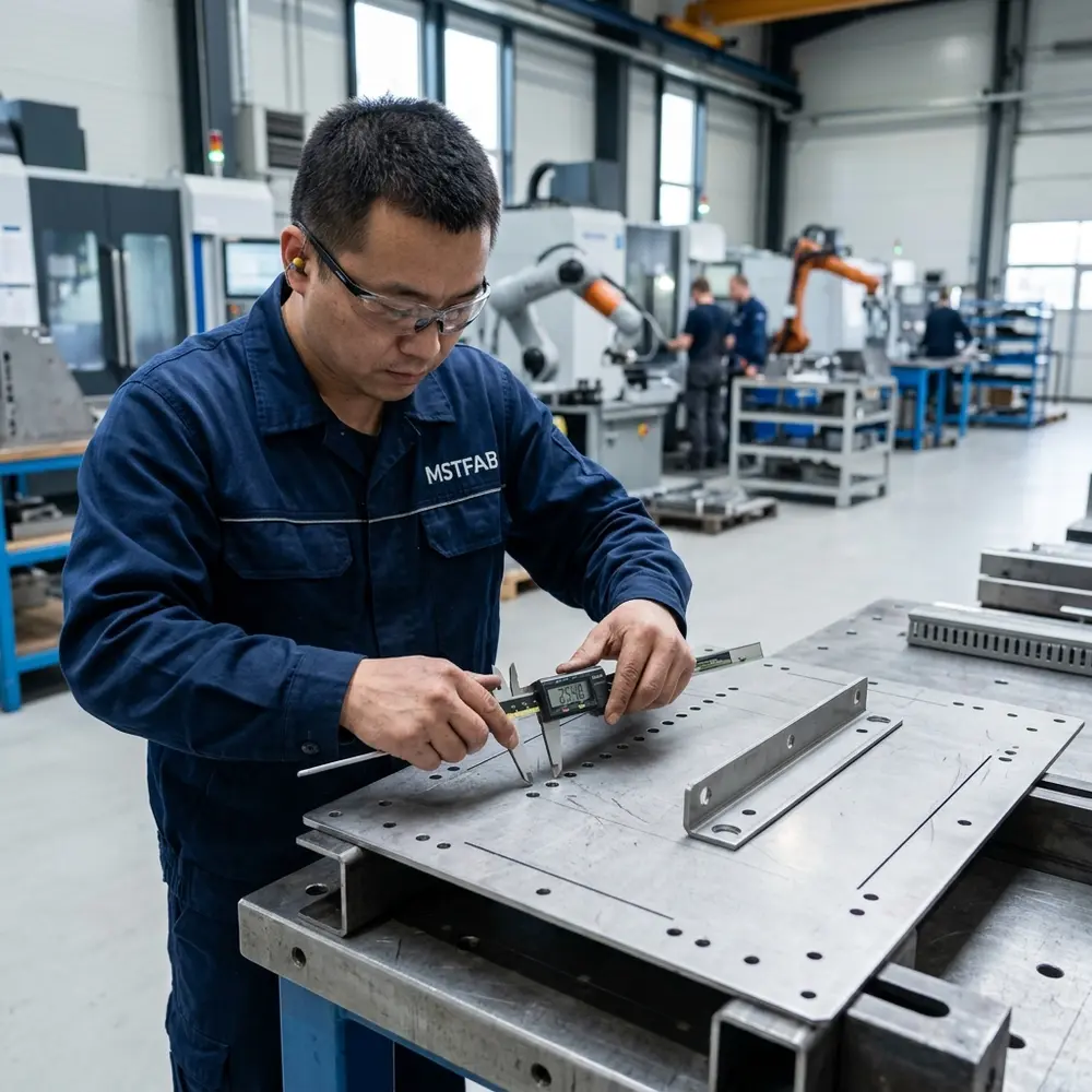
2. Send the actual duct interface, not a familiar nickname
“Standard 40 mm duct” is a purchasing description, not a production definition. Different product families may use different base widths, covers, mounting slots and fastening methods. The RFQ should identify the selected component or provide a controlled mechanical envelope.
- STEP or STP model of the empty enclosure and blank mounting plate
- Controlled 2D drawing with revision
- Duct manufacturer and part number, or approved envelope drawing
- Mounting-hole or slot pattern
- Functional datum and orientation
- Required fastener or insert specification
- Keep-out zones for bends, stiffeners and other metal features
- Finished-condition clearance and masking notes
- First-article characteristics and inspection method
- Prototype and repeat-order quantities

It is excellent for saying “somewhere around here” during a video call. It is less excellent for telling a laser where the hole center belongs.
3. Give the pattern one functional datum
Critical mounting positions should reference a stable feature such as a mounting-plate edge, centerline or buyer-defined equipment datum. Avoid a long chain from cabinet body to bracket to plate to local hole to duct. Every link can be inside tolerance while the final interface quietly moves out of reach.
| Drawing choice | Why it matters to fabrication | Useful evidence |
|---|---|---|
| Pattern from one stable datum | Reduces accumulated location error and simplifies inspection | Coordinate report or dedicated gauge |
| Hole pattern controlled as a group | A long plastic channel can magnify small disagreements between holes | First-article sample or template fit |
| Slots used only where adjustment is intended | Prevents a locating feature from becoming an accidental floating feature | Drawing note identifying locate versus fasten |
MSTFAB can recommend a manufacturable datum or hole strategy, but the customer approves the functional position. The goal is not to sprinkle tight tolerances everywhere. Tolerance is an engineering tool, not drawing confetti.
4. Check the back side before releasing the front side
A hole that looks harmless from the front may land on a formed stiffener, mounting stud, weld seam or cabinet return behind the plate. The interface review should include both sides and the full installation sequence.

Check bends, returns, ribs and stiffeners against hole position and insert-tool access.
Confirm the mounting plate can enter the empty shell without the new bracket or fastener blocking it.
Define screwdriver, rivet-nut or insertion-tool access as a mechanical envelope supplied by the buyer.
Reserve the buyer-approved keep-out zone; MSTFAB does not invent universal electrical service spacing.
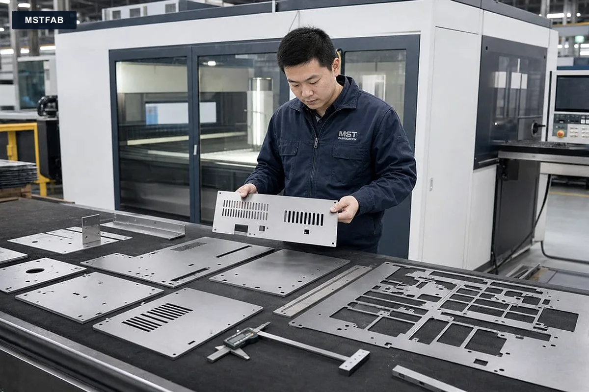
Laser cutting or punching can create the approved holes and slots. Very small holes, thick material or tight positional requirements may need drilling, reaming or another secondary operation. That decision belongs in the manufacturing route, not in a surprise note after coating.
5. Coordinate bends, brackets and installed hardware
Hole-to-bend distance, minimum flange length and press-brake tooling access affect whether a pattern survives forming without stretching or interference. A return flange can stiffen a plate, but it can also occupy the exact space a fastener needs. Sheet metal has a dry sense of humor.
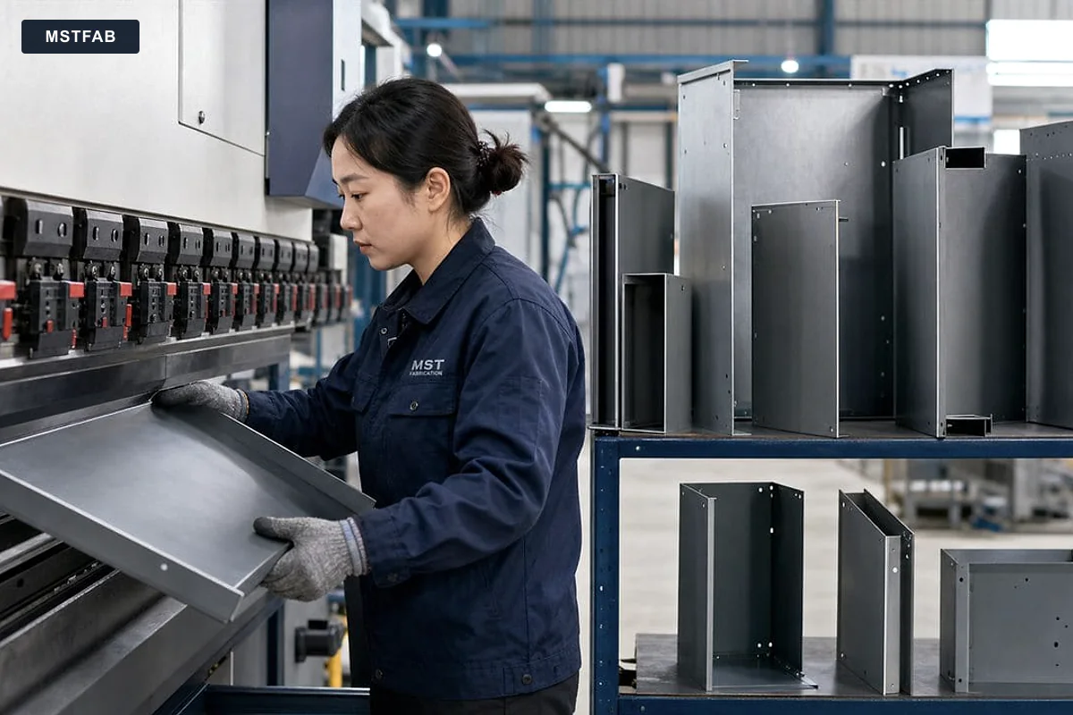
For PEM nuts, studs, rivet nuts or weld studs, specify thread, material, projection, orientation and retention requirement. Review when the hardware is installed: before bending, after bending, before coating or after masking. A perfectly specified insert is less impressive when the installation tool cannot reach it.
Important: MSTFAB verifies drawing-defined metal geometry and agreed hardware installation. The buyer or panel integrator remains responsible for the actual wiring duct, electrical separation, cable fill, bend radius and maintenance procedure.
6. Inspect the interface in the finished condition
Powder coating changes small interfaces. Film buildup can reduce a close hole, fill threads, cover a grounding mask or alter how a template seats. Drawings should state which holes are masked, plugged, chased or accepted after finishing.
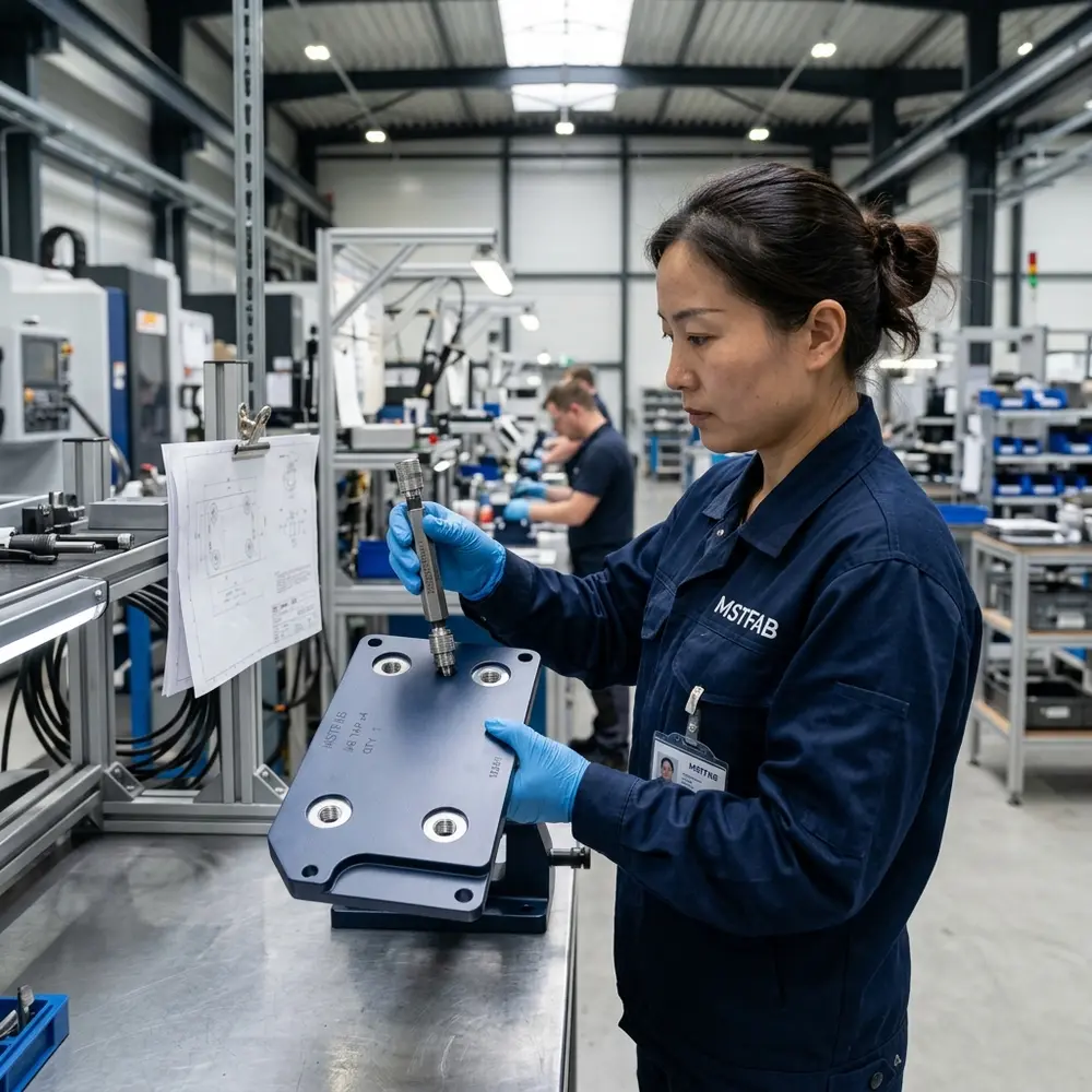
Do not use a bare-metal sample to approve a finished fit when coating affects the interface. If the customer provides a duct base, mechanical template or approved sample, use it on the coated first article. The purpose is mechanical confirmation, not electrical validation.
| Stage | Mechanical check | Buyer pain avoided |
|---|---|---|
| After cutting | Hole size, pattern position, burrs and revision | Misaligned duct base and field drilling |
| After forming and hardware | Plate flatness, backside clearance and insert condition | Rocking duct, blocked tool and weak fastener |
| After coating | Masked areas, threads, locating holes and sample fit | Coating cleanup during electrical assembly |
7. Make the first article answer the important questions
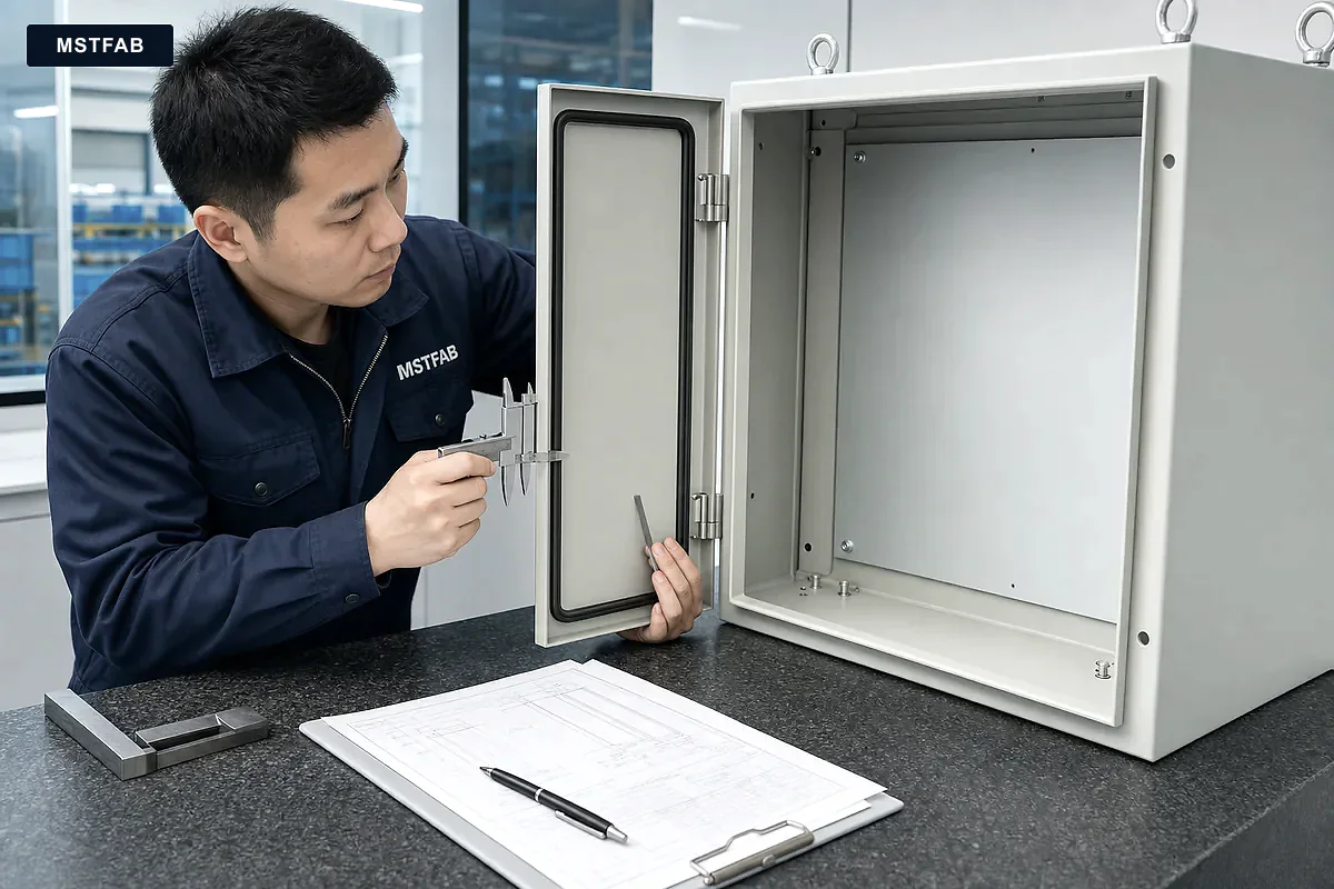
A first article should verify the wiring-duct mounting interface together with the empty shell, blank plate, brackets and installation path. Measuring isolated hole diameters is useful, but it does not prove the pattern fits where the buyer expects.
- Correct drawing and interface revision
- Datum-to-pattern position
- Hole or slot size and spacing
- Plate flatness in the supported condition
- Insert type, orientation and retention
- Clearance from returns, ribs and welds
- Finished thread and masking condition
- Template or buyer-supplied sample fit
- Installation and removal path
- Recorded exceptions and customer approval

For repeat orders, lock the approved revision and record any hand adjustment made during the prototype. If a technician moves one hole by 3 mm and nobody updates CAD, the next batch will faithfully reproduce yesterday’s problem. Manufacturing is obedient like that.
8. Build a quotation package that suppliers can price consistently
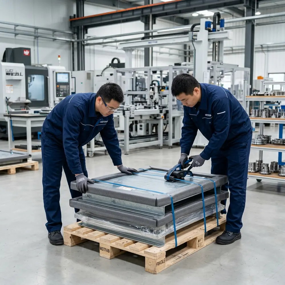
Send the enclosure model, controlled drawing, material, thickness, quantity, selected interface data, hardware, finish, inspection requirement, packing method and destination. Separate prototype and production quantities. Mark the dimensions that actually control customer assembly instead of applying a heroic tolerance to every edge.
For the broader empty-shell manufacturing scope, review MSTFAB’s industrial enclosure fabrication capability. This article stays deliberately narrow: it explains how buyer-approved wiring-duct mounting requirements become reliable sheet metal features without pretending MSTFAB is the electrical integrator.
Frequently asked questions
Does MSTFAB supply or install wiring duct?
No. MSTFAB fabricates the empty shell and drawing-defined metal interfaces. The buyer or panel integrator selects and installs the wiring duct.
Can MSTFAB create holes for DIN rail and wiring duct?
Yes, when the customer supplies approved positions, patterns, datums and hardware requirements. MSTFAB verifies the metal features, not the electrical layout.
Can MSTFAB recommend a universal duct-to-DIN-rail spacing?
No. That spacing depends on customer-selected equipment, wiring, tools and service rules. The buyer defines the envelope; MSTFAB manufactures the approved interface.
Should the first article be checked before or after powder coating?
Both stages can matter, but final sample fit should use the specified finished condition whenever coating affects holes, threads or locating surfaces.
What is the fastest way to quote this enclosure metalwork?
Send the 3D model, controlled 2D drawing, material, quantity, hardware, finish, interface data, inspection points and destination in one revision-controlled package.
Send the metal interface drawing, not the wiring diagram
Share the empty enclosure model, mounting-plate drawing, selected interface envelope, quantities, finish and first-article requirements. MSTFAB will review the cutting, forming, hardware and inspection route.
 WeChat Contact
 WhatsApp Me Directly