
The Short Answer
Applying GD&T to sheet metal fabrication requires adapting solid-block machining rules to thin, flexible, press-brake-formed material—using functional A-B-C datum frames, true position (⊕) with Maximum Material Condition (MMC) on hole patterns, and surface profile (⌓) across formed flanges. Confirming your drawing standard (ASME Y14.5 vs. ISO 1101) and restrained vs. free-state inspection conditions upfront prevents costly metrology disputes.
Explore this guide
01 / GD&T Standards and Non-Rigid Parts
Align ASME Y14.5 or ISO 1101 rules with how thin sheet metal flexes.
Geometric Dimensioning and Tolerancing (GD&T) replaces ambiguous coordinate plus/minus limits with clear functional tolerance zones tied to datum reference frames. However, thin-gauge sheet metal (0.8 mm to 3.0 mm) flexes under its own weight and contains residual rolling and forming stresses—meaning a part that measures out of flatness in a free state often pulls completely flat as soon as mounting bolts are torqued.
Before releasing drawings for quotation, review our guide on reading sheet metal drawings and specify both the governing GD&T edition and whether flexible panels are inspected restrained or in the free state.
Declare ASME Y14.5 vs. ISO 1101
State the exact standard and year (such as ASME Y14.5-2018 or ISO 1101 / ISO 8015) in the title block so rules like Envelope Principle (Rule #1) vs. Independency are unambiguous.
Select stable functional datums (A-B-C)
Choose the primary bolting surface (largest flat mounting flange) as Datum A, and use laser-cut pilot holes or long sheared edges on that same plane as Datums B and C.
Specify restrained vs. free state (Ⓕ)
For large, thin enclosure covers or long brackets, note if flatness and profile tolerances apply while clamped to a simulated mating surface with specified fastener torque.
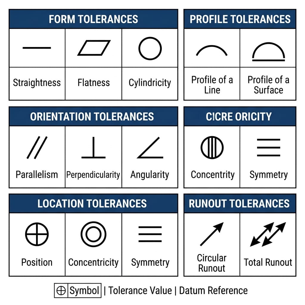
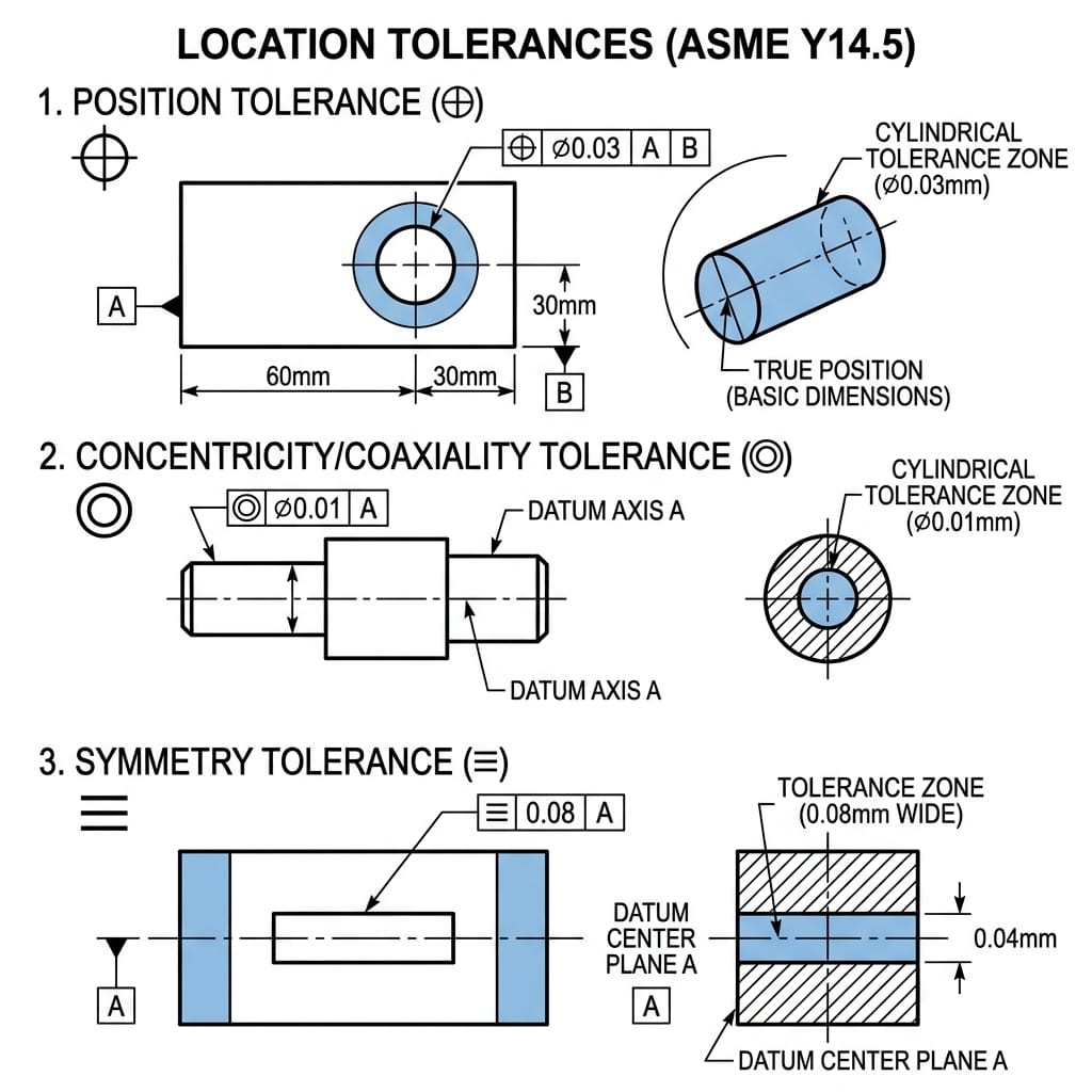
Edition update note: ASME Y14.5-2018 removed the legacy Concentricity (◎) and Symmetry (⌯) symbols because they are costly to inspect and rarely reflect assembly function; use True Position (⊕) or Surface Profile (⌓) on modern sheet metal drawings instead.
02 / Form and Orientation Controls
Apply flatness, perpendicularity, and parallelism where press brakes and coils vary.
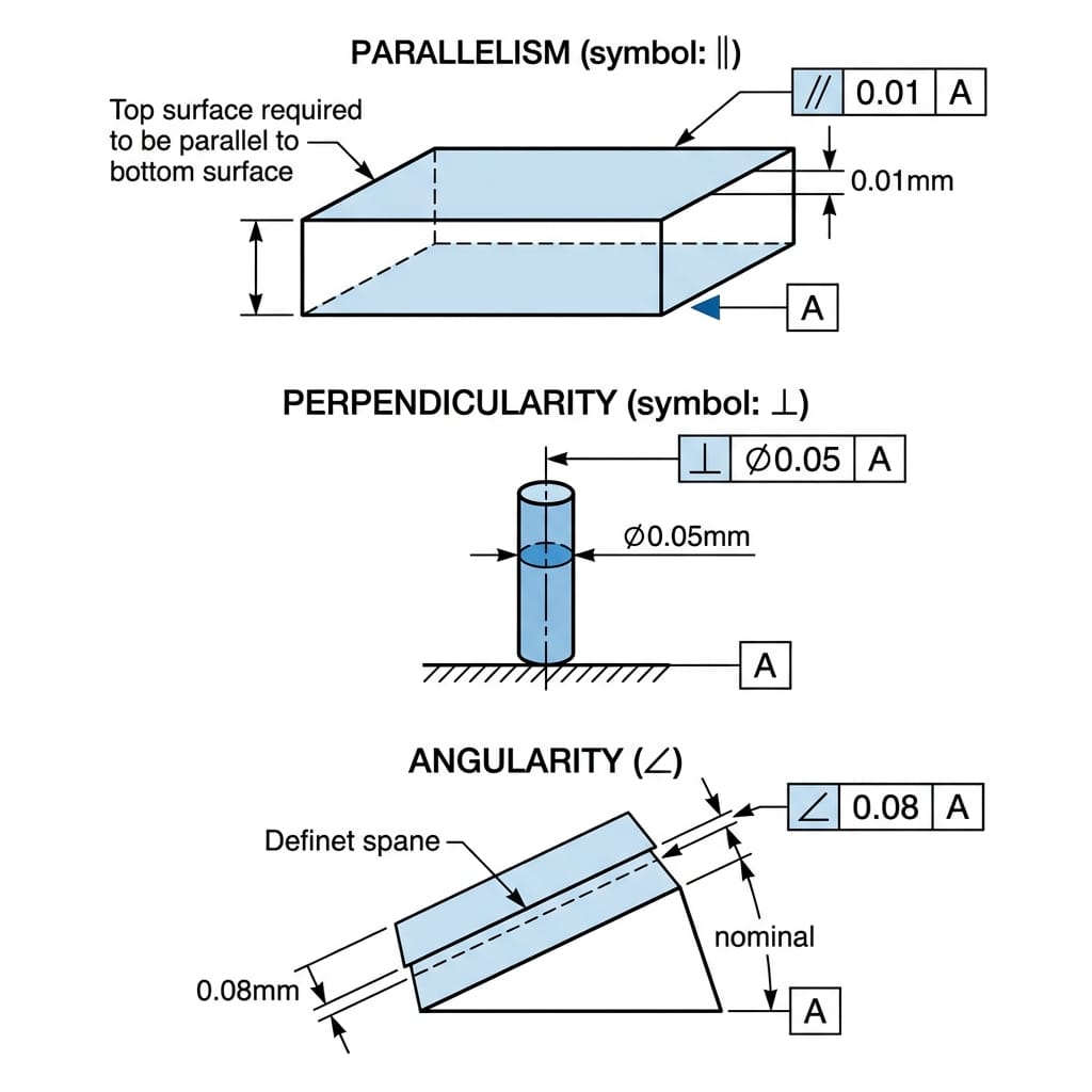
In sheet metal fabrication, form tolerances govern how flat a laser-cut or levelled blank sits, while orientation tolerances govern the angular accuracy of CNC press-brake bends relative to your primary datum.
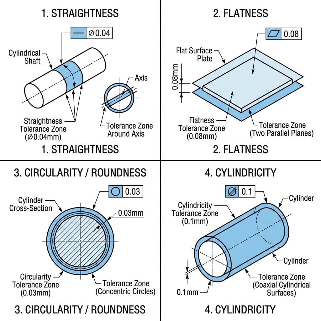
- Flatness (▱) on mounting plates and gasket flanges: Controls coil memory, thermal laser warping, and weld distortion without referencing a datum. Specify per-unit flatness (for example 0.2 mm per 100 x 100 mm) on heatsink pads or busbars rather than an impossible 0.1 mm across a 1000 mm cabinet door.
- Perpendicularity (⊥) on 90-degree formed flanges: Defines a parallel millimeter-wide zone (such as 0.3 mm to 0.6 mm depending on flange height) rather than an angular degree limit—directly controlling how square a vertical bracket wall stands against Datum A.
- Parallelism (∥) on opposing U-channel walls and Z-brackets: Controls the cumulative angular and bend-line offset across two bends, ensuring card-cage guides, drawer slides, and top-hat stiffeners remain parallel.
Because press-brake springback directly drives perpendicularity and parallelism, consult our sheet metal bend radius guide to pair realistic orientation zones with standard inside bend radii.
03 / Location and Profile Controls
Use True Position with MMC for fastener holes and Surface Profile across bends.
Location and profile callouts do the heaviest lifting on OEM sheet metal drawings because they control whether holes align with mating bolts and whether complex bent contours fit inside an assembly envelope.
- Apply True Position (⊕) with the Maximum Material Condition (Ⓜ) modifier on clearance hole patterns and slots—giving manufacturing a cylindrical tolerance zone plus free “bonus tolerance” whenever the laser-cut hole exceeds minimum diameter.
- Separate composite or multi-segment position callouts: keep a tight pattern-locating zone (such as Ø0.15 mm) for holes cut together on the same flat face, and a looser feature-relating zone (Ø0.40 to Ø0.60 mm) when referencing across one or more bends.
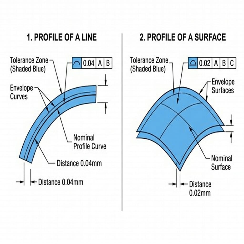
- Use Profile of a Surface (⌓) referenced to Datums A-B-C to control multi-bend brackets, return flanges, and formed enclosure walls simultaneously for location, orientation, and form.
Using MMC on clearance holes lets us verify parts rapidly with functional hard gauges or mating fixtures while guaranteeing 100% bolt-up interchangeability.
Review practical DFM tips for sheet metal enclosure and bracket interfaces →
04 / Designing for Achievable Sheet Metal GD&T
Prevent GD&T failures by isolating critical features from bend deformation.
Even a textbook ASME Y14.5 feature control frame will fail on the shop floor if a tight position or flatness zone is placed inside the plastic deformation zone of a press-brake bend or across an unfixtured weld.
- Keep tight True Position holes on the same flat plane as the datum: Holes cut on the same face as Datums B and C hold Ø0.15 mm position directly off the fiber laser. Every intervening press-brake bend adds +/-0.20 mm to +/-0.35 mm of bend-deduction and thickness uncertainty.
- Add laser-cut bend reliefs near tight-position holes: When a mounting hole must sit closer than 2T + R to a bend line, add a narrow relief slot along the bend line so die pull cannot distort the hole’s circularity or true position.
- Use Projected Tolerance Zones (Ⓟ) for press-fit studs and PEM nuts: When a self-clinching stud or threaded standoff engages a thick mating plate, a small angular tilt in the thin sheet magnifies position error at the tip of the stud.
- Reserve secondary CNC machining for sub-0.05 mm GD&T callouts: If a heavy sheet metal or plate weldment requires 0.05 mm flatness on an IGBT heatsink pad or Ø0.05 mm dowel-pin position, specify post-weld stress relief and local CNC face milling.
Explore our custom sheet metal enclosure fabrication workflow to see how we combine fiber laser cutting, CNC bending, fixture welding, and post-machining.
05 / Tolerance and Inspection Handoff Matrix
Match GD&T feature control frames to realistic sheet metal ranges and gauges.
Use this engineering handoff table to verify that the GD&T callouts on your 2D drawing align with standard sheet metal process capabilities and metrology tools.
06 / Inspection Handoff
Verify datum setups and feature control frames during First Article Inspection.
GD&T only delivers value when the supplier’s quality lab constructs the exact same Datum Reference Frame (A-B-C) specified on your drawing rather than measuring point-to-point with hand calipers.
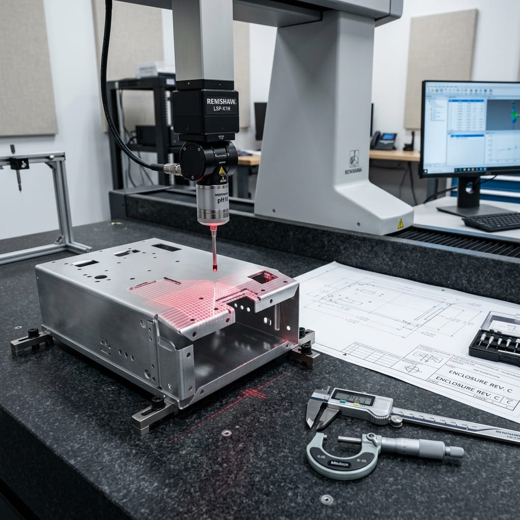
At MSTFAB, our metrology engineers review every GD&T callout during pre-production DFM—confirming how primary datum planes will be staged on the granite surface plate or CMM, calculating MMC bonus tolerances, and designing functional hard gauges for recurring batch runs.
Under our ISO 9001 quality management system, your First Article Inspection (FAI) package maps every ballooned GD&T control frame to its measured value, material certificate (EN 10204 3.1), and setup methodology.
Review our GD&T metrology and First Article Inspection workflow →
07 / Packing and Release
Prevent handling and transit loads from springing formed parts out of GD&T zones.
Thin-walled U-channels, long mounting rails, and open-front enclosure frames can easily bend beyond their perpendicularity or profile tolerance zones if heavy pallets are stacked on top of them during shipping.
Our assembly and export packaging team designs cellular dividers, temporary shipping tie-bars for open frames, foam-lined cartons, and rigid plywood crates so your parts pass incoming CMM and gauge checks upon arrival.
Manufacturing scope: MSTFAB manufactures custom build-to-print sheet metal brackets, chassis, busbars, and empty enclosure shells to customer 3D CAD and 2D GD&T drawings under ISO 9001 quality controls. Final electromechanical assembly and end-product regulatory compliance remain the responsibility of the OEM.
08 / Ready-to-Review RFQ
Include eight details in your GD&T sheet metal RFQ package.
- Nominal 3D STEP modelSupply the exact 3D CAD model so basic dimensions and surface profile contours are unambiguous.
- 2D PDF drawing with GD&T framesCall out all datum targets, basic dimensions, feature control frames, and critical-to-quality flags.
- Governing standard and editionSpecify ASME Y14.5-2018, ASME Y14.5-2009, or ISO 1101 / ISO 2768-mK in the drawing title block.
- Restrained vs. free-state notesDefine clamping forces and datum target areas if thin, flexible panels are inspected in a restrained state.
- Material alloy, temper, and gaugeList exact sheet grade (such as 5052-H32, 304L, SPCC) and thickness so K-factors and springback are predictable.
- Pre-coat vs. post-coat ruleClarify whether True Position and hole size tolerances apply before or after plating, anodizing, or powder coating.
- Secondary CNC machining calloutsIdentify any pads, counterbores, or dowel holes that require post-forming or post-welding CNC milling.
- FAI and metrology deliverablesState whether ballooned FAI reports, CMM point data, or functional check fixtures are required for production.
Review our guide on what files are needed for a sheet metal fabrication quote to package your STEP, DXF, and GD&T PDF drawings cleanly.
Sheet metal GD&T and inspection questions from OEM engineers
Why is True Position (⊕) with MMC better than +/- coordinate tolerances for sheet metal holes?
Coordinate +/-0.15 mm tolerances create a square tolerance zone where corners allow 41% more diagonal variation than the nominal value, yet a part with a slightly off-center hole at maximum clearance size gets rejected on paper even when the bolt fits easily. True Position with MMC (Ⓜ) defines a uniform cylindrical zone and grants extra positional bonus tolerance as the hole size departs from smallest limit.
How should we select Datums A, B, and C on a formed sheet metal bracket or chassis?
Select the primary functional mounting face—usually the largest flat surface that bolts to the parent machine frame—as Datum A (3 points of contact). Then select two perpendicular edges or two laser-cut pilot features located on that exact same flat surface as Datum B and Datum C so the datum frame is not distorted by press-brake bend angles.
What is the difference between ASME Y14.5 and ISO 1101 on a sheet metal drawing?
Under ASME Y14.5 (Rule #1 / Envelope Principle), the size tolerance of a regular feature automatically limits its form variations unless overridden. Under ISO 1101 / ISO 8015 (Independency Principle), size and form are independent unless the Envelope modifier (Ⓔ) is explicitly added. Combining ISO 1101 with ISO 2768-mK is the most common European/Asian baseline.
How do you inspect GD&T on thin sheet metal panels that flex under their own weight?
Thin sheet metal covers and long brackets often sag or exhibit slight coil bow in the free state (Ⓕ). When the engineering drawing specifies restrained inspection per ASME Y14.5 or ISO 10579, we clamp the primary datum targets onto a granite plate or fixture using the drawing’s specified fastener torque before probing profile and position.
Why did ASME Y14.5-2018 eliminate the Concentricity (◎) and Symmetry (⌯) symbols?
Concentricity and Symmetry required deriving median points across opposing surfaces, which was slow to program on CMMs and prone to false rejections from minor surface roughness or edge burrs. Coaxial holes and centered slots on sheet metal parts should be controlled with True Position (⊕) or Surface Profile (⌓).
Can press-brake forming hold a 0.10 mm Surface Profile (⌓) tolerance across multiple bends?
No. Because commercial sheet metal thickness varies within mill tolerances (+/-0.08 to +/-0.18 mm) and grain springback varies slightly across a sheet, multi-bend profiles typically require a 0.50 mm to 1.00 mm profile zone. If an interface truly requires +/-0.05 mm accuracy, we either group those features onto a single laser-cut plane or CNC machine the interface after forming.
Technical references
Reference these foundational geometrical product specification (GPS) and dimensioning standards when authoring 2D sheet metal drawings.
Send your GD&T sheet metal drawings for a pre-production feasibility review.
Upload your 3D STEP models and 2D PDF drawings. MSTFAB will review your datum schemes, bend tolerances, and inspection requirements before quoting.
Request a Sheet Metal Tolerance Review →
Have a question first? caroline@mstfab.com
 WeChat Contact
 WhatsApp Me Directly