
The Short Answer
Effective sheet metal enclosure tolerancing separates flat-pattern laser accuracy (+/-0.10 mm) from formed flange tolerances (+/-0.25 mm to +/-0.50 mm) and welded frame envelopes (ISO 2768-m or +/-1.0 mm). Applying blanket machining tolerances across a multi-bend cabinet inflates fabrication cost without improving assembly fit; instead, assign tight callouts only to functional datum holes, subpanel mounting pitches, and gasket compression flanges.

Explore this guide
01 / Process Capability Baseline
Understand achievable tolerances across laser cutting, CNC bending, and welding.
Sheet metal enclosures pass through four distinct physical transformations: flat thermal cutting, plastic deformation on a press brake, thermal fusion during welding, and high-temperature curing in a powder-coat oven. Each stage introduces cumulative dimensional variance that behaves very differently from CNC milling of a solid aluminum block.
Before releasing drawings, consult our guide to reading sheet metal drawings and match your dimensional callouts to the real capability of each manufacturing stage.
Fiber laser cutting (+/-0.10 to +/-0.15 mm)
Features cut in the same flat plane—such as connector cutouts, mounting hole patterns, and PEM fastener pilots—hold the highest accuracy because no bend springback is involved.
CNC press brake bending (+/-0.25 to +/-0.50 mm)
Single bend-to-edge dimensions hold +/-0.25 mm on thin gauges, while multi-bend return flanges accumulate coil thickness variation and angular springback (+/-0.5 to +/-1.0 deg).
Welded enclosure frames (+/-0.50 to +/-1.50 mm)
Fixture-clamped TIG and MIG welded cabinets hold tight functional squareness, while overall outer envelope spans across 600 mm to 2000 mm follow general welded structure tolerances.
Stack-up warning: Never chain four consecutive bend dimensions across an enclosure U-channel without leaving one open relief dimension—otherwise every +/-0.25 mm flange tolerance stacks directly into the mating cover width.

02 / General Tolerance Standards
Use ISO 2768-mK as your title-block baseline without over-constraining the shell.
Most international OEM enclosure drawings specify ISO 2768-m (Medium) or ISO 2768-mK in the title block to govern untoleranced linear, angular, and geometrical dimensions. Understanding what ISO 2768-m actually permits prevents surprises during incoming inspection.
- Short linear spans (0.5 mm to 30 mm at +/-0.1 to +/-0.2 mm): Covers hole diameters, slot widths, edge-to-hole margins, and short return hems where laser cutting and precision backgauges easily comply.
- Medium enclosure spans (30 mm to 400 mm at +/-0.3 to +/-0.5 mm): Applies to subpanel mounting pitches, box depths, and formed door widths—achievable with controlled CNC press-brake setups and verified K-factors.
- Large cabinet dimensions (400 mm to 2000 mm at +/-0.8 to +/-1.2 mm): Governs overall cabinet height and width where thermal weld shrinkage and sheet flatness require fixture control rather than micrometer limits.
When an assembly problem arises despite ISO 2768-m compliance, review our sheet metal enclosure fit and rework checklist to isolate whether hole-to-bend stack-up or coating buildup is the culprit.

03 / Critical Functional Zones
Concentrate tighter tolerances on sealing flanges, rack rails, and mating interfaces.
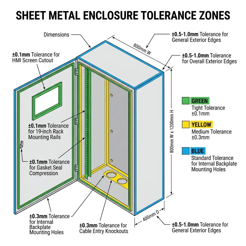
Rather than tightening the entire drawing, high-performing OEM engineering teams divide an enclosure into three functional tolerance zones—allocating precision setup time only where mechanical function demands it.
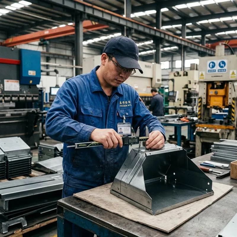
- Zone A (Tight / Critical Fit): Keep PCB standoff clusters, D-sub / optical bulkhead cutouts, and lock-cam engagement holes on the same flat laser face (+/-0.10 mm to +/-0.15 mm) so bend variations cannot shift alignment.
- Zone B (Controlled Forming & Sealing): Hold door return flanges, knife-edge gasket lips, and 19-inch EIA rack-rail hole pitches to +/-0.25 mm to +/-0.35 mm with flatness controls so IP gaskets compress uniformly.
- Zone C (Standard Structural Envelope): Allow standard ISO 2768-m or c tolerances on exterior roof overhangs, plinth base skirts, and non-mating louver clearances to keep unit fabrication costs competitive.
Combining smart zoning with fixture-controlled sheet metal welding services ensures doors close flush and internal subplates drop onto mounting studs effortlessly.
Explore 8 enclosure shell fabrication checks before drawing release →
04 / Datum Selection and Coating Allowance
Dimension from functional datums and specify pre-coat vs. post-coat limits.
Two of the most frequent disputes between OEM buyers and enclosure fabricators stem from measuring across opposing bends instead of a shared datum, and forgetting that powder coating adds physical thickness to every edge and hole.
- Establish a single mounting datum per panel: Dimension internal component holes from one primary bend flange or one datum pilot hole rather than chaining dimensions from both left and right sidewalls.
- Use slotted mounting holes across weldments: Pair round datum holes on one side of a removable subpanel with obround slots (for example 7 x 11 mm for M6 studs) on the opposite side to absorb cabinet thermal expansion and weld tolerances.
- Account for powder coating film buildup (0.06 to 0.12 mm per side): An exterior textured powder coat reduces clear hole diameters by up to 0.24 mm and closes telescoping door-to-frame gaps by nearly 0.50 mm across two painted edges.
- State explicitly whether tolerances apply before or after coating: Add a clear drawing note indicating whether tight connector cutouts and grounding pins are inspected pre-plate/pre-coat or require masking and post-coat gauging.
For outdoor sealed cabinets, review our NEMA 4X outdoor enclosure OEM shell guide to balance gasket compression tolerances with corrosion-resistant finishes.
05 / Buyer Control Matrix
Align enclosure feature tolerances with shop-floor verification methods.
Use this reference table when preparing 2D engineering drawings and specifying incoming inspection criteria for custom enclosures.
06 / Inspection Handoff
Verify flat blanks, formed panels, and assembled cabinet gaps before batch release.
Catching a bend-deduction error after 100 cabinets are welded and powder coated guarantees costly scrap and schedule slippage. Tolerance control must happen progressively at each workstation.
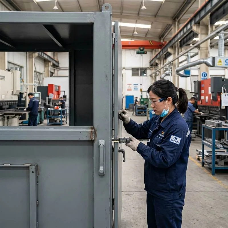
At MSTFAB, first-piece flat laser blanks are verified against CAD overlays before bending begins. Press brake operators validate first-off flange lengths and angles with calibrated digital protractors, and welding inspectors check frame diagonals and door reveal gaps in dedicated assembly fixtures.
Every new enclosure project includes a documented First Article Inspection (FAI) report tied to your ballooned 2D PDF drawing under our ISO 9001 quality system, giving your engineering team complete dimensional proof before full production.
Explore our sheet metal metrology and First Article Inspection process →
07 / Packing and Release
Preserve door alignment and cabinet squareness during international freight.
A precision-built sheet metal enclosure can easily be racked out of tolerance if stacked improperly in a shipping container or strapped without internal door blocks.
Our export packaging workflow uses high-density foam spacers between doors and frames, rigid corner protectors, moisture-absorbing desiccants, and custom fumigation-free plywood crates so your enclosures arrive square and ready for integration.
Manufacturing scope: MSTFAB manufactures custom build-to-print sheet metal enclosures, cabinets, subpanels, and brackets to OEM drawings under ISO 9001 quality controls. Electrical wiring, active component assembly, and final end-equipment regulatory certifications remain the responsibility of the OEM.
08 / Ready-to-Review RFQ
Include eight tolerance details in your sheet metal enclosure RFQ.
- 3D STEP assembly and part filesProvide nominal 3D geometry for the enclosure body, doors, subpanels, and mounting brackets.
- Ballooned 2D PDF drawingsHighlight critical-to-quality (CTQ) dimensions that require tighter control than general title-block limits.
- General tolerance standardCall out ISO 2768-m or ISO 2768-mK clearly for all non-critical linear and angular dimensions.
- Functional datum schemeIndicate which mounting face, hinge axis, or pilot hole serves as Datum A, B, and C.
- Material grade and nominal gaugeSpecify CRS (SPCC), galvanized (SGCC), stainless (304/316L), or aluminum (5052-H32) with exact thickness.
- Pre-coat vs. post-coat noteState whether tight cutout tolerances and thread fits apply before or after powder coating/plating.
- Sealing and flatness targetsDefine gasket compression thickness, door flatness allowance, and weld seam tightness requirements.
- FAI and inspection deliverablesNote if a full dimensional FAI report, CMM report on critical brackets, or trial assembly check is required.
Clearly distinguishing critical mating zones from standard structural dimensions allows our engineers to build the right fixtures and quote competitive unit pricing.
Sheet metal enclosure tolerance questions from OEM engineers
Is ISO 2768-m tight enough for a custom sheet metal electrical or telecom enclosure?
ISO 2768-m (Medium) is the ideal baseline for overall enclosure dimensions, non-critical flanges, and weldment envelopes. However, you should still add specific bilateral tolerances (+/-0.10 mm to +/-0.20 mm) on precision connector cutouts, PCB standoff pitches, and latch engagement features.
Why do holes positioned across a press-brake bend have looser tolerances than holes on a flat face?
Holes cut on the same flat face rely purely on the fiber laser’s CNC gantry positioning (+/-0.10 mm). Once a sheet is bent on a press brake, coil thickness variations (+/-0.08 to +/-0.15 mm), grain direction, and angular springback shift the formed flange position, requiring +/-0.25 mm to +/-0.40 mm across the bend.
How close to a bend line can we place a mounting hole without distorting its tolerance?
To prevent the hole from stretching into an oval or teardrop shape during press-brake forming, keep the nearest edge of the hole at least 2x material thickness plus the inside bend radius (2T + R) away from the bend tangent line—or add a laser-cut bend relief slot.
How much clearance should we leave between a flush inset enclosure door and the surrounding frame?
For powder-coated sheet metal enclosures, design a nominal 1.5 mm to 2.0 mm per-side reveal gap in bare metal CAD. After welding tolerances, hinge pin play, and 0.08–0.12 mm of powder coating on both mating edges, this yields a clean, non-binding 1.2 mm to 1.8 mm finished gap.
How do you control flatness on large sheet metal cabinet doors so the IP gasket seals evenly?
Large flat sheet metal panels naturally oil-can unless stiffened. We form perimeter return flanges (typically 15 mm to 25 mm deep), weld internal hat-section or perforated door stiffener rails using low-heat pulsed sequences, and verify flange flatness on a reference table before coating.
Can you hold CNC machining tolerances (+/-0.02 mm) on a sheet metal part if required?
Standard laser cutting and press brake forming cannot hold +/-0.02 mm directly. However, when a sheet metal chassis or heavy bracket requires precision bearing bores, dowel pin holes, or milled heat-sink pads, we perform secondary CNC machining after forming or welding.
Technical references
Reference these international standards when specifying general linear, angular, geometrical, and thermal cutting tolerances on sheet metal enclosure drawings.
Send your enclosure drawings for a tolerance and DFM feasibility review.
Share your 3D STEP models and 2D PDF drawings. MSTFAB will review your critical tolerance zones, bend stack-up, and datum scheme before quoting.
Request an Enclosure Tolerance Review →
Have a question first? caroline@mstfab.com
 WeChat Contact
 WhatsApp Me Directly