
The Short Answer
Preventing thermal distortion and bending failures in sheet metal fabrication requires controlling heat input and bend geometry at the DFM stage—before parts reach the welding table. By combining interlocking tab-and-slot joint design, copper chill-bar welding fixtures, balanced skip/stitch welding sequences, and proper press brake grain orientation and bend reliefs, OEMs eliminate warped frames, cracked radii, and ovalized mounting holes.
Explore this guide
01 / Thermal Distortion Physics and Fixture Control
Stop sheet metal weld warping by controlling heat input, restraint, and sequence.
Thin-gauge sheet metal (0.8 mm to 3.0 mm) has low structural stiffness relative to the intense localized heat of an welding arc. As the molten weld pool cools and solidifies, longitudinal and transverse shrinkage forces pull surrounding panels inward—causing oil-canning buckling on flat enclosure sides, twisted chassis diagonals, and binding cabinet doors.
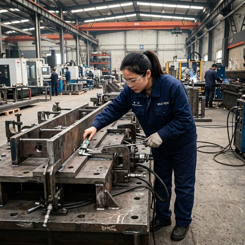
Rather than trying to hammer or flame-straighten warped assemblies after the fact, our custom sheet metal welding engineers prevent distortion through joint design, heatsink tooling, and symmetrical heat sequencing.
Interlocking tab-and-slot joints
Laser-cut self-fixturing tabs and slots locate mating flanges accurately with minimal gap, reducing required filler metal and arc dwell time by up to 40%.
Copper chill-bar clamping jigs
Rigid toggle-clamp fixtures backed by high-conductivity copper or aluminum chill bars draw heat rapidly out of the heat-affected zone (HAZ) while restraining expansion.
Balanced skip and backstep sequence
Instead of running one continuous seam down a long thin flange, welders alternate opposing corners and use backstep stitch sequences to balance shrinkage vectors.
Design-for-welding rule: Never over-specify continuous structural fillet welds on thin internal sheet metal stiffeners where intermittent stitch welds (such as 25 mm weld on 100 mm centers) provide full mechanical rigidity at a fraction of the thermal heat load.
02 / Eliminating Structural Weld Defects
Prevent porosity, undercut, burn-through, and lack of fusion in thin-gauge welds.
Even when an assembly stays flat, internal or surface weld defects compromise fatigue life under vibration and create pinholes or craters that bleed rust through powder coating. Tight parameter discipline and pre-weld edge preparation eliminate the four primary sheet metal weld failures.
- Weld porosity (gas pockets): Caused by hydrocarbons, stamping oils, moisture, or zinc vapor trapped in the molten pool. Prevented by solvent degreasing, grinding zinc coatings back 3–5 mm from the weld toe on galvanized steel, and maintaining laminar argon/helium shielding gas flow.
- Edge undercut and gouging: Occurs when excessive voltage or travel speed melts away the base metal along the weld toe without wetting in filler wire, creating a stress-riser notch. Controlled via pulsed current waveforms and calibrated torch angles.
- Burn-through and melt-back: Common on sheets under 1.5 mm when root gaps exceed 0.5 mm. Solved by holding tight CNC press brake flange tolerances so mating edges touch cleanly without wide gaps, paired with copper backing bars.
- Cold lap and lack of fusion: Happens when laser-cut oxide scale is left on carbon steel edges or travel speed is too fast for root penetration. Eliminated by nitrogen laser cutting or pre-weld rotary edge conditioning.
Every welded subassembly passes visual inspection per ISO 5817 quality levels before advancing to surface treatment and powder coating.
03 / Press Brake Bending Root-Cause Fixes
Eliminate outer-radius cracking, hole ovalization, and corner tearing during forming.
Accurate welding fit-up is impossible if upstream press brake parts suffer from cracked corners, pulled mounting holes, or inconsistent flange angles. Most sheet metal bending defects trace back to three preventable DFM mistakes on the flat pattern.
- Prevent outer bend radius cracking by orienting primary bend lines perpendicular to the sheet rolling grain direction and specifying ductile alloys (such as 5052-H32 instead of 6061-T6 aluminum) with an inside bend radius of at least 1x to 1.5x material thickness.
- Stop hole and slot ovalization near bends by keeping hole edges at least 2.5x material thickness plus inside bend radius away from the bend tangent line—or by widening relief slots across the bend zone.
- Eliminate corner tearing where two adjacent flanges meet by laser-cutting obround or circular bend relief notches (minimum width >= 1x thickness, depth >= thickness + bend radius) at every bend intersection.
Reviewing your 3D STEP model against our press brake V-die library catches radius cracking and hole pulling before the first laser nest is programmed.
Review our CNC press brake bending guidelines and DFM standards →
04 / Welding Process Selection
Match TIG, pulsed MIG, or handheld fiber laser welding to gauge and cosmetic requirements.
No single welding process is optimal for every sheet metal joint. Selecting the right heat source balances penetration depth, travel speed, thermal heat input (kJ/mm), and post-weld cosmetic grinding labor.
- Precision GTAW / TIG welding (0.8 mm – 3.0 mm): Delivers pinpoint heat control, spatter-free beads, and clean autogenous or filler-fed corner seams on stainless steel, aluminum, and cosmetic cold-rolled steel cabinets.
- Pulsed GMAW / MIG welding (2.0 mm – 10.0 mm): Provides high deposition rates and deep structural fusion for heavy equipment frames, mounting skids, and thick carbon or 5083 aluminum brackets.
- Handheld & automated fiber laser welding (0.8 mm – 4.0 mm): Produces an ultra-narrow heat-affected zone at 3x to 5x the travel speed of TIG, cutting thermal distortion and post-weld grinding time dramatically on long enclosure seams.
- Resistance spot & capacitor-discharge stud welding: Joins internal stiffener hat-channels and installs threaded M3–M8 earth/mounting studs rapidly without marring the exterior cosmetic A-surface.
Explore our sheet metal DFM design guide to see how joint geometry and flange return widths affect welding access.
05 / Engineering Control Matrix
Confirm five distortion and forming controls before releasing drawings to production.
Use this technical checklist during design sign-off to prevent thermal warping and press brake defects across prototype and batch runs.
06 / Inspection Handoff
Validate bend angles, weld integrity, and assembly flatness prior to finishing.
Inspecting a welded enclosure only after powder coating hides root fusion issues and makes dimensional corrections impossible without stripping the finish. Quality verification must lock geometry at both the press brake and the welding bay.
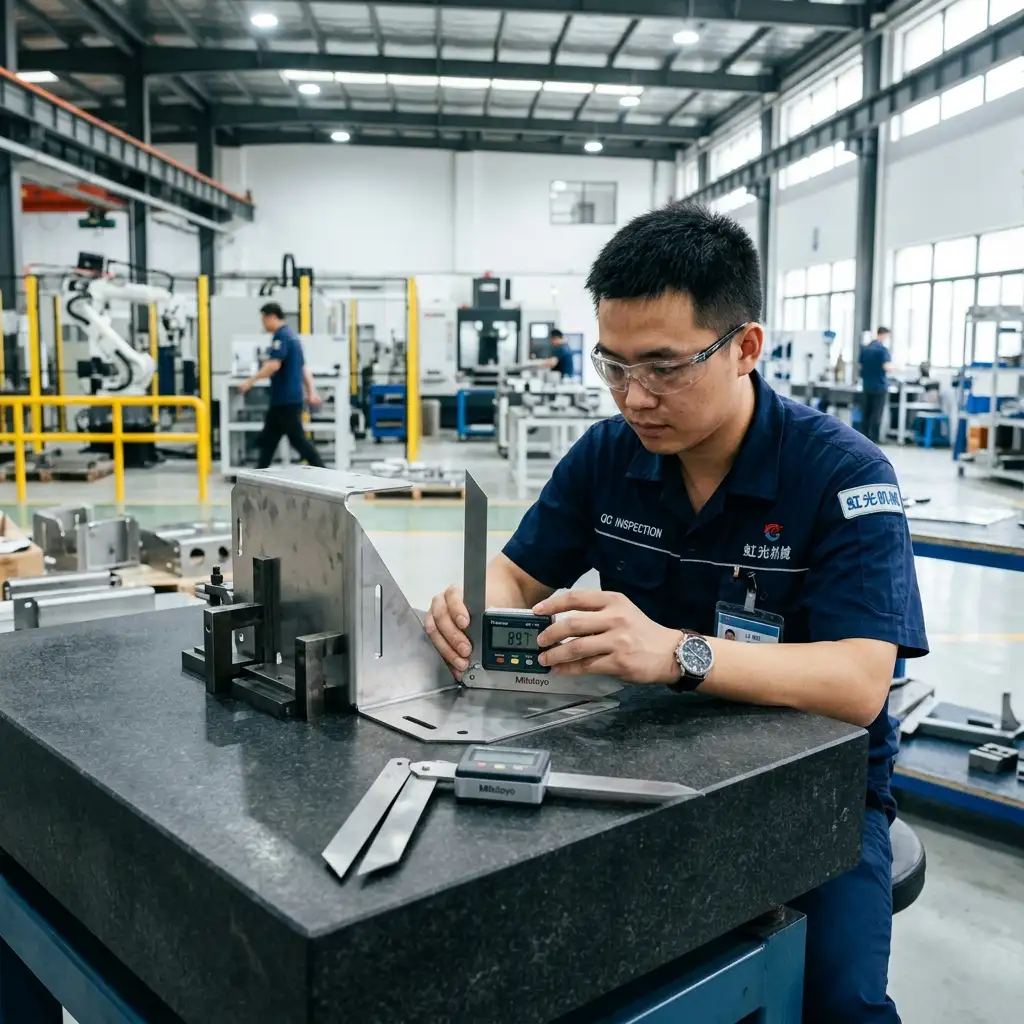
Our QC inspectors measure first-off formed flanges with calibrated digital protractors and height gauges, verify welded frame diagonals and mounting surface flatness on granite inspection tables, and conduct liquid dye-penetrant or leak testing when sealed seams are specified.
All dimensional data and weld inspections are documented under our ISO 9001 and IATF 16949 quality systems so your engineering team receives full First Article traceability.
07 / Stress-Free Packing and Scope
Prevent transit racking distortion with rigid export crating.
A precision-welded cabinet or chassis frame that leaves the factory square within 1.0 mm can still rack out of alignment if Forklift handling or stacked ocean freight applies uneven torsional loads to unbraced doors and openings.
Our export packaging team bolts or braces heavy enclosures onto reinforced plywood pallet bases, installs protective foam corner columns, and wraps bare or coated surfaces against moisture so assemblies arrive ready for your integration line.
Manufacturing scope: MSTFAB manufactures custom build-to-print sheet metal brackets, precision weldments, and empty enclosure shells under ISO 9001, IATF 16949, and ISO 14001 standards. Final electrical integration, powered testing, and end-equipment certification belong to the OEM.
08 / Ready-to-Review RFQ
Include eight technical details in your welded and formed sheet metal RFQ.
- 3D STEP assembly modelProvide the full 3D STEP (.stp) assembly along with individual sheet metal part models.
- 2D PDF drawing with weld symbolsIndicate ISO 2553 / AWS weld symbols, stitch lengths, pitch spacing, and critical flatness tolerances.
- Alloy and temper specificationCall out exact grade and temper (e.g., SPCC, Q235B, SS 304L, or 5052-H32 aluminum) to prevent bend cracking.
- Inside bend radius calloutsState nominal inside bend radii or permit MSTFAB to match standard press-brake V-die radii during DFM.
- Cosmetic weld finish mapClearly mark A-surface seams requiring flush smooth grinding vs. internal structural seams left as-welded.
- Critical datum hole tolerancesHighlight mounting holes near bend lines that require tight positional accuracy after forming and welding.
- Leak or non-destructive testingSpecify if dye-penetrant inspection, chalk-kerosene testing, or water-spray ingress checks are required.
- Surface finish and batch volumeDetail powder coat RAL/texture, anodizing, passivation, and initial FAI sample vs. recurring lot size.
Submitting both 3D STEP models and 2D weld/tolerance callouts lets our engineers design custom welding fixtures and optimize bend reliefs before cutting steel.
Welding distortion and press brake bending questions from OEM engineers
How do you keep large thin-gauge sheet metal panels from oil-canning during welding?
Oil-canning occurs when weld shrinkage along the perimeter compresses a large unreinforced panel. We prevent it by adding folded return flanges or spot-welded internal hat-section stiffeners, using interlocking tab-and-slot joints to minimize heat input, clamping copper chill bars along the seam, and utilizing low-heat fiber laser or pulsed TIG skip-welding sequences.
Why do mounting holes near a 90-degree bend stretch into ovals, and how do we fix it?
When a hole sits inside the plastic deformation zone of a press brake die shoulder, the tensile stretching of the outer sheet fibers pulls the hole edge into an teardrop or oval. To prevent this without secondary machining, place hole edges at least 2.5x sheet thickness plus inside bend radius away from the bend line, or add a stress-relief slot between the hole and the bend.
When should we choose fiber laser welding over traditional TIG welding for sheet metal?
Handheld or automated fiber laser welding is ideal for long linear seams on 0.8 mm to 4.0 mm stainless steel, carbon steel, and aluminum enclosures. Because its energy density is concentrated into a tiny spot with 3x–5x faster travel speed, the heat-affected zone is ultra-narrow—dramatically reducing thermal warping and post-weld grinding.
How do you prevent outer bend radius cracking on aluminum sheet metal parts?
First, we verify the alloy temper—recommending formable 5052-H32 rather than brittle 6061-T6 for tight 90-degree bends. Second, we lock laser nesting layouts so high-stress bend lines run perpendicular to the mill rolling grain, and select punches with an inside radius of at least 1x to 1.5x sheet thickness.
Can you weld pre-galvanized steel without creating porosity and weak joints?
Yes. Zinc vaporizes at around 907 °C while steel melts near 1,500 °C; if welded directly over heavy zinc coating, boiling zinc gas becomes trapped in the weld pool as severe porosity. We either mechanically strip/laser-ablate the zinc along the joint edges prior to welding or use silicon-bronze MIG brazing to preserve corrosion protection with minimal zinc burn-off.
What flatness and diagonal tolerances can you hold on custom welded enclosures?
Using dedicated modular welding tables, precision toggle fixtures, and balanced weld sequencing, we routinely hold general welded frame tolerances to ISO 2768-mK / ISO 13920 Class B (typically +/-1.0 mm to +/-1.5 mm diagonal squareness on mid-to-large cabinets), with tighter local flatness achieved on critical mounting faces.
Technical references
Reference these international welding and geometrical tolerance standards on your 2D fabrication drawings to establish clear acceptance criteria.
- ISO 5817 — Welding: Fusion-Welded Joints in Steel, Nickel, Titanium and Their Alloys (Quality Levels for Imperfections)
- ISO 13920 — Welding: General Tolerances for Welded Constructions (Lengths, Angles, Shape and Position)
- ISO 2768-1 / 2768-2 — General Tolerances for Linear, Angular and Geometrical Dimensions
Eliminate warping and bending failures in your next sheet metal production run.
Send your 3D STEP models and 2D PDF drawings to MSTFAB. Our engineering team will review your weld joints and bend geometry and return a complete DFM and production quote.
Request a Welding & Forming Quote →
Have a question first? caroline@mstfab.com
 WeChat Contact
 WhatsApp Me Directly